http://go.warwick.ac.uk/lib-publications
Original citation:Dutton, B., et al. (2011). Exploring surface wave interaction with angled defects in the near and far field. Journal of Physics: Conference Series, 278(1), article no. 012011. Permanent WRAP url:
http://wrap.warwick.ac.uk/40120
Copyright and reuse:
The Warwick Research Archive Portal (WRAP) makes the work of researchers of the University of Warwick available open access under the following conditions. Copyright © and all moral rights to the version of the paper presented here belong to the individual author(s) and/or other copyright owners. To the extent reasonable and practicable the material made available in WRAP has been checked for eligibility before being made available.
Copies of full items can be used for personal research or study, educational, or not-for-profit purposes without prior permission or charge. Provided that the authors, title and full bibliographic details are credited, a hyperlink and/or URL is given for the original metadata page and the content is not changed in any way.
Publisher’s statement:
© 2012 IOP Publishing
A note on versions:
The version presented here may differ from the published version or, version of record, if you wish to cite this item you are advised to consult the publisher’s version. Please see the ‘permanent WRAP url’ above for details on accessing the published version and note that access may require a subscription.
Exploring surface wave interaction with angled defects in the
near and far field
B. Dutton, A.R. Clough, M.H. Rosli and R.S. Edwards
Department of Physics, University of Warwick, Coventry, CV4 7AL, UK
Email: [email protected]
Abstract. This paper explores some effects that occur when using laser ultrasound to scan defective samples. Surface defects can often propagate at an angle to the surface; however, for calibration, slots machined normal to the surface of the sample are typically used. Several interesting angle-dependent effects are observed when Rayleigh waves interact with angled surface defects, and are explored here using measurements and models for a scanning laser detector (SLD) or scanning laser line source (SLLS) scanned across the defect. Reflection and transmission coefficients are calculated for different crack angles and lengths. Additionally, interesting angle-dependent effects are observed in the Rayleigh wave amplitude and frequency enhancements in the near field when using SLD or SLLS.
1. Introduction
Ultrasound has proven to be a suitable technique for characterising surface cracks, particularly by analysing the reflection or transmission of Rayleigh waves, which have both in-plane (IP) and out-of-plane (OP) components [1-3]. Previous work on slot defects machined normal to the surface has shown that the transmission of broadband Rayleigh waves can be analysed in both the time and frequency regimes and used as a measure of crack length [4,5]. Real cracks, however, can propagate at an angle to the surface normal; for example rolling contact fatigue (RCF) in rails which propagates at around 25º to the surface. For this reason, our work considers a range of crack angles and lengths and the effect they have on surface waves, using both experimental and modelling techniques. Far field effects, such as the reflection and transmission coefficients of a Rayleigh wave following interaction with a crack, are explored for a wide range of angles and lengths. Enhancements in the near-field have been previously observed with a scanning laser detection (SLD) or scanning laser line source (SLLS) for limited number of angles [2,3,6], and this work considers these enhancements for a wider range of crack angles.
2. Model and experimental details
A 3D finite element method model using PZFlex was used to explore the interaction of ultrasound with surface cracks. The model used a loading force derived from a laser pulse duration of 10 ns
,
simulating a larger sample, with symmetry applied to improve model efficiency. Figure 1 shows the location of generation and detection points for the SLD case with the detection point scanned across the crack, while for SLLS scans the generation and detection positions are switched and the generation line source scanned.
Figure 1. Model and experimental sample details. The SLD technique is shown and for SLLS the source and detection were reversed. Dimensions in mm.
Experimental scans were performed on aluminium samples with dimensions 150x150x50mm, using a non-contact laser-ultrasound system. The dimensions were chosen such that bulk acoustic waves (BAW) would not interfere with the Rayleigh wave. A Nd:YAG laser with 10ns rise time was used to generate surface waves in the thermoelastic regime. The laser beam was focused into a line of approximate dimensions 6 mm by 300 μm, to enhance generated ultrasound in a direction which is perpendicular to the line
,
in addition to increasing the frequency content of the generated surface waves [10,11].
A two-wave mixer interferometer from IOS was used to detect OP displacements on unpolished aluminium surfaces. Fabricated aluminium samples with crack angles from 30º to 150º relative to the surface, and a fixed length d of 2 mm, were used. Generated models had defect angles ranging from 10º to 170º and lengths from 1 to 4 mm.3. Far field: reflection and transmission coefficients
(a) (b)
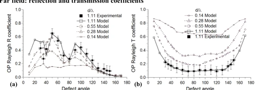
Figure 2. OP reflection and transmission coefficients for selected normalised crack lengths from 0.14 to 1.11, where (a) shows a general increase of reflection coefficient as d/λ increases, while (b) shows a decrease of transmission coefficient as d/λ increases.
We first explore the effect of crack angle and length on Rayleigh reflection and transmission coefficients, using both model and experimental data. OP reflection coefficients were calculated from A-Scan data as the amplitude ratio of reflected Rayleigh over incident Rayleigh wave. Figure 2(a) shows the model (line and open squares) and experimental (filled squares) reflection coefficients for a crack length to central wavelength ratio of d/λ = 1.11, where λ is the central wavelength of the broadband incident pulse, showing very good agreement. The same figure also shows reflection coefficients for smaller d/λ of 0.55, 0.28 and 0.14, showing a progressive decrease of amplitude, as expected when considering the broadband nature of the pulse and the fact that the majority of the energy in the Rayleigh wave is contained within one wavelength of the sample surface. Corresponding calculations were performed for the transmission coefficients using model and experimental data, with the coefficient also measured more than three wavelengths past the crack opening. Figure 2(b) shows the model and experimental transmission coefficients for d/λ = 1.11, showing very good agreement.
Al sample Laser line source
(fixed) Detection
150 50
50
θ
Crack detail
d (0.5 to 4.8)
θ
0.5
[image:3.595.86.492.414.557.2]The same figure also shows calculated transmission coefficients for smaller d/λ, showing the expected change in transmission coefficient. It is evident that a variation in transmission with angle must be considered when comparing results from real defects and calibrations based on slots which are machined normal to the surface [12].
4. Near field: amplitude and frequency enhancements
An enhancement in both the amplitude and frequency content of Rayleigh waves has been observed when scanning close to a crack which is normal to the sample surface [3,6,9]
.
The behaviours were explored using both SLD and SLLS techniques, and using other non-contact ultrasonic techniques.
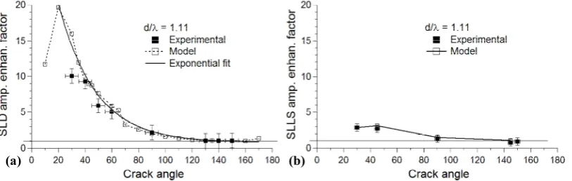
We consider here the effect crack angle has on these enhancements, which has previously been ignored.Figure 3(a) shows the calculated amplitude enhancement from both experimental and modelled data for the SLD technique, where the enhancement was calculated as the ratio of the highest amplitude in the windowed Rayleigh arrival time, which occurs close to the edge of the crack, to the incident Rayleigh wave amplitude. Modelled and experimental data show very good agreement, with a slightly reduced enhancement in the experimental data due to the larger detection point size [6]. Model and experimental data show an approximately exponential dependence on angle; a fit was performed using model data excluding the 10º angle crack, and is shown as a solid line. As a reference, the horizontal line indicates a ratio of 1, i.e. no enhancement. An enhancement increase is clearly visible as the crack angle decreases, with significant angle dependence for angles < 60º. Positive interference of reflected Rayleigh and mode converted waves contribute to this enhancement, as has previously been reported for cracks normal to the surface [1,6], but the very large enhancement that occurs for shallow crack angles requires further investigation, which will be reported in a later work [13].
Similar analysis was performed for the SLLS technique, shown in Figure 3(b), where only a few data points are shown due to models taking considerably longer to run than SLD. In this case, the enhancement is due to interference effects, but also source truncation and changing boundary conditions [8,9]. Overall, like the SLD amplitude enhancement vs. crack angle, the enhancement during SLLS also has an angle dependence, but this is much less significant than that observed using SLD.
[image:4.595.93.500.480.609.2](a) (b)
Figure 3. OP amplitude enhancement factors of both modelled and experimental scans for d/λ = 1.11, where (a) shows SLD, and (b) SLLS technique.
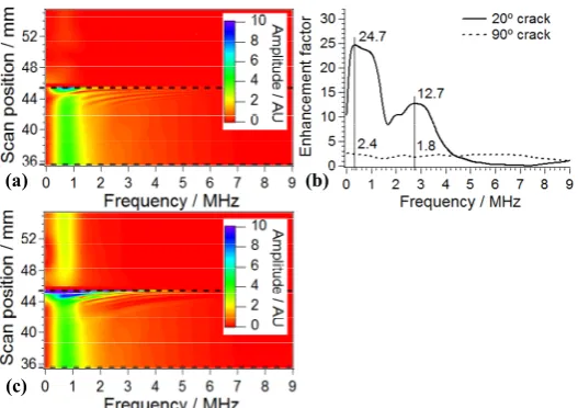
the 20º crack shows considerably larger enhancements. The vertical lines indicate peaks for the 20º crack, occurring at 0.3 and 2.7 MHz. High frequency enhancements due to non-linear effects have been reported for SLS [9]; enhancements at the Rayleigh central frequency, 0.81 MHz, are 23.5 and 2.1 for 20º and 90º respectively, which are similar to the enhancement in Figure 3(a); enhancements occurring at frequencies lower than the Rayleigh central frequency will be discussed in a future publication [13].
(a) (b)
[image:5.595.74.338.199.385.2](c)
Figure 4. Magnitude FFT B-scan of OP displacement model output using SLD technique for (a) 90º crack and (c) 20º crack, and their corresponding frequency enhancement factors (b).
5. Conclusion
Modelled reflection and transmission coefficients using the SLD technique agree well with experimental data for crack angles from 30º to 150º. It is evident that variations in both reflection and transmission coefficients with angle must be considered when comparing results from real defects with calibrations based on slots which are machined normal to the surface. It was also shown for the SLD technique that very large amplitude enhancements occur at shallow crack angles, with significant angle dependence observed when comparing enhancements with those from cracks normal to the surface [6,8,13]. Amplitude enhancements were obtained with the SLLS technique and again show angle dependence, but at a much lower scale. For SLD, a larger frequency enhancement was found at a small angle of 20º than with the 90º crack angle for a large range of frequencies. These amplitude and frequency enhancement techniques could potentially be used to identify cracks at different angles in real samples, and used as a fingerprint of the position of a defect.
References
[1] Jian X, et al., Journal of Applied Physics, 2007. 101(6): p. 7.
[2] Kinra VK, Journal of the Acoustical Society of America, 1986. 79(6): p. 1688-1692. [3] Kromine AK, et al., Materials Evaluation, 2000. 58(2): p. 173-177.
[4] Edwards RS, Dixon S, and Jian X, Ultrasonics, 2006. 44(1): p. 93-98.
[5] Vu BQ and Kinra VK, Journal of the Acoustical Society of America, 1985. 77(4): p. 1425-1430. [6] Edwards RS, et al., Applied Physics Letters, 2005. 87(19): p. 3.
[7] Arias I and Achenbach JD, International Journal of Solids and Structures, 2003. 40(25): p. 6917-6935.
[8] Arias I and Achenbach JD, Wave Motion, 2004. 39(1): p. 61-75.
[9] Dixon S, et al., Nondestructive Testing and Evaluation, 2008. 23(1): p. 25-34.
[10] Aindow AM, Dewhurst RJ, and Palmer SB, Optics Communications, 1982. 42(2): p. 116-120. [11] Hutchins DA, Canadian Journal of Physics, 1986. 64(9): p. 1247-1264.