www.ijiset.com
11
Design and Performance Analysis of Low Pass Fir Filter
Using Different Windows Techniques
Manoj Chandra DeyP
1
P
, Smriti BaxlaP
2
P
, Pranay Kumar RahiP
3
P
, Muzaherul HaqueP
4
• • P
1,2
P
Lecturer, P
3,4 P Assistant Professor, • P 1,2,3 P
Department of Electrical and Electronics Engineering, Institute of Technology, Korba, • Chhattisgarh, India.
•
ABSTRACT
•
In communication system digital filters plays a significant role as it provides high attenuation to the unwanted signals and at same time offers very low attenuation to the desired signals. Inthis paper, Low pass filter is designed using different window techniques namely Parzen, Nuttall and Rectangular. Here the Magnitude and phase response in time and frequency domain of these window techniques have been compared using MATLAB simulation. From the simulation result of different window, we found Nuttall window gives better magnitude and phase response as compared to other two techniques.
Keywords: - FIR, DSP, Digital filter, Low pass
filter, Nuttal Window, Parzen Window,
Rectangular Window
•
1. INTRODUCTION
•
• A fundamental aspect of signal processing is filtering. In signal processing, there are many instances in which an input signal to a system contains extra unnecessary content or additional noise which can degrade the quality of the desired portion [2]. Digital filters play an important role in digital signal processing applications. A digital filter is a mathematical algorithm implemented in hardware / software that operates on a digital input to produce a digital output [1]. In signal processing, a filter is a device or process that removes from the unwanted component of the signal. Digital filter are classified into two categories and they are the Finite Impulse Response (FIR) filter and Infinite Impulse Response (IIR) filter [3]. In the FIR system, the impulse response is of finite duration, and has finite number of nonzero terms. On the other hand, the IIR system has an infinite number of nonzero terms [4]. FIR filters are one of the primary types of filters used in
DSP.
For the design of low pass FIR filters complex calculations are required. Mathematically, by substituting the values of the pass band, transition width, pass band ripple, stop band attenuation, sampling frequency in any of the methods from window method we can get the values of filter coefficients h (n)[2].
2. SYSTEM DESIGN AND ANALYSIS
A finite Impulse Response (FIR) filter are type of digital filters and consists of weighting sequence (impulse response) among non-recursive digital filters which is finite in length. The simple form of FIR filters is coming through the windowing method. So, in this section, we have described mathematical model equation for various window functions. The Window functions are widely used for different applications of digital signal processing such as signal analysis, signal estimation, digital filter design and speech processing. Fourier series method with windowing is the most straight forward technique to design FIR filters[2]. The desired frequency response of any digital filter is periodic in frequency and can be expanded in Fourier series ,i.e.,
HRdR(℮P
jω
P
) =∑∞𝒏=−∞𝐡RdR(n)eP
-jω P ………(1) Where,P P
hRdR(n)=P
𝟏
𝟐𝝅∫ 𝐇( 𝟐𝝅 𝟎 eP
jω
P
) eP
jωn
P
dω ….(2)
The coefficients of the series hd(n) are identical to the impulse response of a digital filter[1]. The impulse response of the ideal low pass filter can easily be found as follows:
𝒉
𝑳𝑷[𝒏] = 𝐬𝐢𝐧 𝝎𝒄𝒏𝝅𝒏
, − ∞ < 𝑛 < ∞
…
…
(3) There are essentially three well-known methods for FIR filter design:www.ijiset.com
12
2) FIR filter design using frequency samplingmethod.
3) Optimal or Minimax FIR filter design [4]. But throughout this paper we have discussed the window method for designing the low pass FIR filter. Some of the windows commonly used are as follows:
2.1 NUTTALL WINDOW
The Nuttall window has the widest main lobe and lowest maximum side lobe level among the Blackman, Exact Blackman, and the Blackman-Harris window. The equation for the Nuttall window is [5]
𝝎(𝒏) = 𝒂𝟎− 𝒂𝟏 𝒄𝒐𝒔 �𝟐𝝅𝑵 − 𝟏� + 𝒂𝒏 𝟐 𝒄𝒐𝒔 �𝟒𝝅𝑵 − 𝟏�𝒏
−𝒂𝟑 𝒄𝒐𝒔�𝟔𝝅𝑵−𝟏𝒏 �(4)
Where n=0,1,2, … N-1
The equation for the periodic Nuttall
𝝎(𝒏) = 𝒂𝟎− 𝒂𝟏 𝒄𝒐𝒔 �𝟐𝝅𝒏𝑵� + 𝒂𝟐 𝒄𝒐𝒔 �𝟒𝝅𝒏𝑵� −
𝒂𝟑 𝒄𝒐𝒔 �𝟔𝝅𝑵𝒏� (𝟓)
where n= 0,1,2, ... 1. The periodic window is N-periodic. The coefficients for this window are given in table
Table 1. Coefficient of Nuttall window
𝑎0 0.3635819
𝑎1 0.4891775
𝑎2 0.1365995
𝑎3 0.0106411
2.2 PARZEN WINDOW
The following equations defines the N- point Parzen
window [6] over the interval −(𝑁−1)
2 ≤ 𝑛 ≤
(𝑁−1) 2
𝝎(𝒏) =
�𝟏 − 𝟔 �
|𝒏| 𝑵/𝟐�
𝟐
+ 𝟔 �𝑵/𝟐|𝒏|�𝟑 𝟎 ≤ |𝒏| ≤ (𝑵 − 𝟏)/𝟒
𝟐 �𝟏 −𝑵/𝟐|𝒏|�𝟑 𝑵−𝟏𝟒 ≤ |𝒏| ≤𝑵−𝟏𝟐 (𝟔)
2.3 RECTANGULAR WINDOW
The Rectangular Window has the highest amount of spectral leakage. The rectangular function truncates the signal to within a finite time interval. The weighting function for the Rectangular window is to be defined [1] by
𝝎𝑹(𝒏) = � 𝟏, 𝐟𝐨𝐫 |𝒏| ≤
𝑴 − 𝟏 𝟐 𝟎, 𝐨𝐭𝐡𝐞𝐫𝐰𝐢𝐬𝐞 (𝟕)
3.
DESIGN SIMULATION
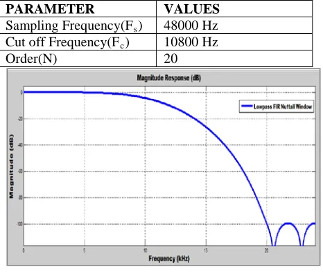
To design the low pass FIR filter using MATLAB Nuttall Parzen and Rectangular Window the parameter specifications are given in table 2. as
Table 2: Parameter Specification
PARAMETER VALUES
Sampling Frequency(FRsR) 48000 Hz
Cut off Frequency(FRcR) 10800 Hz
Order(N) 20
Fig.1 Magnitude Response of Nuttall Window Technique
www.ijiset.com
13
Fig.3 Magnitude [dB] and Phase[rad]of Nuttall Window Technique
Fig. 4 Filter coefficient on Nuttall Window Technique
Fig. 1 shows the magnitude response of Nuttall window and Fig. 2 shows phase response of Nuttall window. The magnitude response contains ripples in stop band and good pass band response.
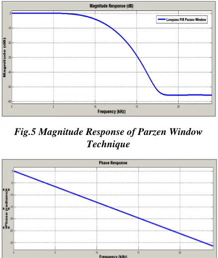
Fig.5 Magnitude Response of Parzen Window Technique
Fig.6 Phase Response of Parzen Window Technique
Fig.7 Magnitude [dB] and Phase [rad]of Parzen Window Technique
Fig. 8 Filter coefficient on Parzen Window Technique
Magnitude and phase response of Parzen window is shown in Fig. 5 and 6. In this method magnitude response contains negligible ripples in stop band and it is also having good pass band response.
Fig.9 Magnitude Response of Rectangular Window Technique
www.ijiset.com
14
-4.5 -4 -3.5 -3 -2.5 -2 -1.5 -1 -0.5 0 0.5 1
1 2 3 4 5 6 7 8 9
M
ag
ni
tu
de
(d
B
)
Frequency (kHz)
Nuttall
Parzen
Rectan gular
Fig.11 Magnitude [dB] and Phase [rad]of Rectangular Window Technique
Fig. 12 Filter coefficient on Rectangular Window Technique
Fig. 9 and 10 shows the magnitude and phase response of Rectangular window. The magnitude response shows very good pass band response but stop band contains very large amount of ripples.
4.
COMPATIVE ANALYSIS
Fig.13 Magnitude [dB] Vs Frequency [kHz] Plot of Nuttall, Parzen and Rectangular Window
5.
RESULT
Table 3: Magnitude and Frequency Result of Nuttall, Parzen & Rectangular window Frequency
(in kHz)
Magnitude (in dB) Nuttall
window
Parzen Window
Rectangular Window
1 0 0 -0.219
2 0 0 -0.497
3 0 0 -0.313
4 -0.021 0 0.033
5 -0.084 -0.028 -0.095 6 -0.258 -0.147 -0.584 7 -0.631 -0.458 -0.527 8 -1.315 -1.098 0.230 9 -2.449 -2.226 0.361 10 -4.175 -4.007 -1.740
From the Matlab simulation resultofNuttall, Parzen and Rectangular window at sampling frequency 48000Hz, cut off frequency 10800 Hz and order 20, table 4 shows that Nuttall window has higher gain than Parzen and rectangular window.
6.
CONCLUSIONS
In this research paper, Low pass filter has been designed and simulated using three different Window Techniques namely Nuttall, Parzen and Rectangular. After analysing the performance of proposed FIR filter by their magnitude and phase response using MATLAB simulation at same values of sampling frequency 48kHz, cut off frequency 10.8kHz and order of 20, we conclude that Rectangular window has better pass band response as compared to Nuttall and Parzen Window but it contains more ripples in stop band, whereas Parzen window shows minimum ripples in stop band and Nuttall Window has good magnitude response.
REFERENCES
1) S Salivahanan and C Ghanapriya, “Digital Signal Processing”, Tata Mc Graw -Hill, 2P
nd
P
Edition, pp. 430-469, 2011.
www.ijiset.com
15
Electrical Engineering (ICAEE), 2013International Conference on. IEEE, 2013.
3) Yu-Chi Tsao and Ken Choi, “Hardware-Efficient VLSI Implementation for 3-Parallel Linear-Phase Fir Digital Filter of Odd Length”, Circuits and Systems (ISCAS), IEEE Conference, ISBN: 978-1-4673-0218-0, pp. 998-1001, 2012.
4) V.Soni, Shukla P. and Kumar M., “ Application of Exponential Window To Design A Digital Nonrecursive Fir Filter”, IEEE International Conference on Advanced Communication Technology (ICACT), ISBN: 978-1-4244-8830-8, pp.1015-1019, 2011.
5) Nuttall, Albert H. “Some windows with very Good Side lobe behaviour”, IEEE Transactions on Acoustic, Speech and Signal Processing, pp. 01-03, February’ 1981.
6) Harris F.J., "On the Use of Windows for Harmonic Analysis with the Discrete Fourier Transform", Proceedings of the IEEE, vol. 66, No. 1, January’1978.
AUTHORS
Manoj Chandra Dey received the Bachelor of Engineering Degree in Electrical and Electronics Engineering from Institute of Technology, Korba, Chhattisgarh Swami Vivekanada Technical University, Bhilai, India in 2013.
He is a Lecturer in the Department of Electrical and Electronics Engineering, Institute of Technology, Korba India.
Smriti Baxla received the Bachelor of Engineering Degree in Electrical and Electronics Engineering from Institute of Technology, Korba, Chhattisgarh Swami Vivekanada Technical University, Bhilai, India in 2014 and persuing Masters of Engineering in Power System from Technocrats
Institute of Technology Bhopal, Madhyapradesh India. Working as a Lecturer in Electrical and Electronics Engineering of Institute of Technology, Korba India.
Pranay Kumar Rahi received the Bachelor of Engineering Degree in Electronics and Telecommunication Engineering from Government Engineering College, Guru Ghasidas University, Bilaspur, Chhattisgarh, India in 2004 and
pursuing Masters of Engineering in Electronics and Communication Engineering from National Institute of Technical Teachers’ Training and Research, Punjab University, Chandigarh, India. Working as a Assistant Professor in Electrical and Electronics Engineering of Institute of Technology, Korba since 2008. He has authored 14 research publications and published a number of journal papers and research paper in the leading International and National journal. His primary research interest includes Digital Signal Processing, VLSI Design, Control Systems and Digital Electronics and Logic Design.
![Fig.13 Magnitude [dB] Vs Frequency [kHz] Plot of Nuttall, Parzen and Rectangular Window](https://thumb-us.123doks.com/thumbv2/123dok_us/7859506.1303636/4.612.76.300.460.661/fig-magnitude-frequency-plot-nuttall-parzen-rectangular-window.webp)
