10.15662/ijareeie.2014.0308079
Copyright to IJAREEIE www.ijareeie.com 11466
Comparison of an Efficient Buck Converter
Configuration for the DC Power Distribution
Of Future Green Data Centers
Sindhu Shetty1, I. V. Prasanna2, S. K. Panda3
UG student, Dept. of EEE, National Institute of Technology Karnataka, India1
Research Engineer, Dept. of ECE, National University of Singapore, Singapore2
Associate Professor, Dept. of ECE,National University of Singapore, Singapore3
ABSTRACT: The internet and the demand for online connectivity are fuelling the energy consumption in Data Centers. According to DataCenterDynamics 2012 Global Census, the power requirements grew by 63% globally to 38GW, up from 24GW in 2011. The census estimated a further rise of 17% to 43GW in 2013. It is important that this growing demand for energy is met by the power supply from renewable energy sources. The Power SupplyDistribution System for FutureData Centers is shifting towards DC Architecture from existingAC architecture. In this paper, 380V DCis considered as the transmission voltage and 48 V DCas the distribution voltage inside the Data Centers. An efficient 380V to 48V DC-DC buck converter withless switching and thermal losses can reduce the cooling requirements of the Data Center. In this directiona suitableconfiguration is selected by comparingTwo- Stage, Half-Bridge, Push-Pull and Full-Bridge buck converters based on efficiency and power loss analysis.
KEYWORDS: Buck Converter, Full-Bridge, Push-Pull, Two-Stage, Half-Bridge,Isolated, DC distribution, Data Center
I. INTRODUCTION
The Simulink models of the Two-Stage, Half-Bridge, Push-Pull and Full-Bridge are presented in Section II. The output voltage equations are also given in each sub-section; these can be used for obtaining the duty cycle of the switches. Vin refers to the input voltage, Vout – output voltage, D – duty cycle, Ns – number of turns on transformer secondary and Np – number of turns on transformer primary. Section III presents the analysis and observations of the simulation results. Based on the efficiency and power loss curves, Full-Bridge is selected as the most suitable configuration and its simulation results are presented. Also a table of comparison of the four configurations is given. Section IV presents the conclusion and future scope.
II.BUCKCONVERTERMODELS
A. Two-Stage Converter
The Two-Stage converter is a non-isolated converter that achieves the required conversion in two stagebuck operations. It has four active switches and can provide gain up to 8.The main drawback is that it does not provide isolation between the source and the load. This can be considered for applications where protection/isolationis not required. The Simulink model of the Two-Stage converter is shown in Fig. 1 which is indicative of the topology. The output voltage is given by Eq. 1.
Vout= 0.5VinD (1)
Fig. 1 Simulink Model of Two-Stage Buck Converter
B. Half -Bridge Converter
The voltage stress on the active switches in theHalf-Bridge is less than that of Full-Bridge and Push-Pull configurations. The voltage appearing across the transformer primary winding is one half of the input voltage. It has two active switches but it also contains two extra capacitors.
Vout= 0.5VinD (Ns/Np) (2)
10.15662/ijareeie.2014.0308079
Copyright to IJAREEIE www.ijareeie.com 11468
C. Push-Pull Converter
The Push pull has a center-tap on the primary of the transformer which imposes a voltage of more than twice the input voltage on the two switches. Push-Pull topology faces problems of transformer flux imbalance if the transistors and the transformer windings are not perfectly matched. The secondary rectification side can be either a center-tapped full wave rectifier or a bridge rectifier. The output voltage equation is given in Eq. 3.
Vout= 2VinD (Ns/Np) (3)
Fig. 3 Simulink Model of Push-Pull Buck Converter
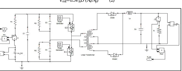
D. Full-Bridge Converter
The Full-Bridge has four active switches and the voltage stress across the switches does not exceed the input voltage. Similar to Half-Bridge and Push-Pull, the Full-Bridge topology also suffers from transformer saturation problems. The duty cycle is obtained by using Eq. 4.
Vout= VinD (Ns/Np) (4)
III. ANALYSISANDOBSERVATIONS
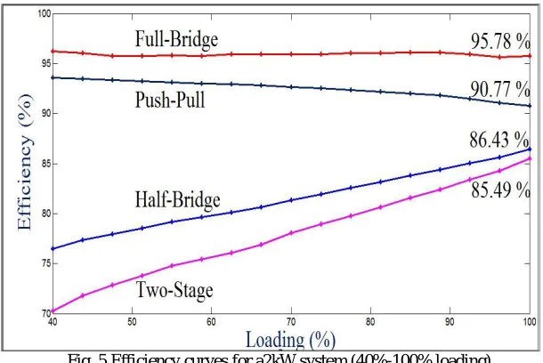
The efficiency is calculated as the ratio of the output power to the input power. The efficiency curves for the four configurations from 40 % loading to full load are plotted in Fig. 5. The full load power is 2 kW. IGBT switches are considered as the switching frequency is set at 20 kHz. The input voltage is fixed at 380 V and the output required is 48 V. All the passive component values are kept same wherever possible, to maintain uniformity. The analysis is done on the steady-state characteristics.
Fig. 5 Efficiency curves for a2kW system (40%-100% loading)
The power loss is calculated as the difference between input power and the output power. The full load power loss for the considered configurations is shown in Fig 6.
10.15662/ijareeie.2014.0308079
Copyright to IJAREEIE www.ijareeie.com 11470 From Figs. 5and6, it can be observed the Full-Bridge converterprovides the highest efficiency than the other three configurations. Moreover, the efficiency does not vary much from 40% loading to full load unlike the other topologies. This is very important for Data Center applications where the load on the servers keeps varying throughout the day. Full-Bridge converter has the least power loss of 71W for a full load power of 2 kW.
The best configuration for a particular application depends on many factors like power level, size, cost etc. Table I provides a comparison of various factors for the configurations which will help in theselection of the converter.
Parameter Configuration
Half-Bridge Push-Pull Full-Bridge Two-Stage
No. of Active Switches 2 2 4 4
Duty cycle ~0.50 ~0.50 ~0.50 ~0.25 Voltage stress across the
active switches
>=190 V >= 760 V 380 V 380 V
Transformer primary winding
One primary winding
Center tap in primary winding
One primary winding
NA
Transformer turns ratio (Np/Ns)
2 8 4 NA
Full load Efficiency (for 2kW system)
86.43% 90.77% 95.78% 85.49 %
Full load Power Loss (for 2kW system)
284 W 158 W 71 W 326 W
Table. I
The use of four switches in Full-Bridge is justified for high power and high input applications as the voltage stress across the switches does not exceed input voltage. Current mode control is recommended to mitigate the transformer saturation problems in the case of Full-Bridge and Push-Pull topologies.
Considering these factors, the Full-Bridge Converter is selected for an efficient Data Center DC distribution system. Simulation results of the output voltage, output current and the input current of the Full-Bridge converter are shown in Fig. 7. The input voltage is 380 V and the load resistance R = 2 ohm.
IV. CONCLUSION
The 380 V DC transmission and 48 V DC distribution architecture was considered for the Data Centers. To achieve the 380 V to 48 V DC-DC buck conversion, four configurations namely Two-Stage, Half-Bridge, Push-Pull and Full-Bridge were analyzed and compared. The Full Full-Bridge is found to be the most efficient configuration for the considered power level of 2 kW. The future work is directed towards implementing phase-shift controlled Full Bridge converter with ZVS (zero voltage switching) to reduce the thermal losses by which the overall efficiency can be improved.
REFERENCES
[1] Xiaogao Xie, Zhaoming Qian, “A new two-stage buck converter for voltage regulators,” IEEE Power Electronics Specialists Conference, 2008,
pp. 1580-1584
[2] Moschopoulos, G., Jain ,“Single-stage ZVS PWM full-bridge converter”, IEEE Transactions on Aerospace and Electronic Systems, Oct. 2003,
pp.1122- 1133
[3] Hiraki. E, Hirao, K, Tanaka. T, Mishima. T, “A push-pull converter based bidirectional DC-DC interface for energy storage systems”, 13th EuropeanConference on Power Electronics and Applications, 2009. EPE '09, pp.1-10
[4] Nayak D.K, Reddy S.R, “Performance of synchronous rectified push-pull converter”, International Conference on Emerging Trends in Electrical and Computer Technology (ICETECT), 2011, pp. 321-325
[5] J. A. Sabate , V. Vlatkovic , R. B. Ridley , F. C. Lee and B. H. Cho "Design considerations for high-voltage high-power full-bridge zero-voltage-switched PWM converter", Proc. Appl. Power Electron. Conf., 1990, pp.275 -284
[6] M. Ilic and D. Maksimovic "Phase-shifted full bridge dc-dc converter with energy recovery clamp and reduced circulating current", Proc. IEEE Appl. Power Electron. Conf., 2007pp.969 -975
[7] A. Bendre , S. Norris , D. Divan , I. Wallace and R. W. Gascoigne "New high power dc-dc converter with loss limited switching and lossless secondary clamp", IEEE Trans. Power Electron., 2003vol. 18, no. 4, pp.1020 -1027
[8] Ramesh Khanna, Satish Dhawan., “Design Considerations for High Step-Down ratio Buck Regulators”, Integrated Digital Conference [Online],
indico.cern.ch
[9] Hyosang Jang, Taeyoung Ahn, Byungcho Choi, “New half-bridge dc-to-dc converters for wide input voltage applications”,31st InternationalTelecommunications Energy Conference, 2009 (INTELEC)., pp. 1-6