Simulation of Shunt Active Power Filter Connected to a
Photovoltaic Array for Compensating Current
Harmonics in Single Phase System
K.Srinivas1, G.Srinivas2, Dr.K.Narasihma Rao 3
PG Student, Dept. of EEE, Gayatri Vidya Parishad College of Engineering, Visakhapatnam, India1
Assistant Professor, Dept. of EEE, Gayatri Vidya Parishad College of Engineering, Visakhapatnam, India2
Professor & HOD, Dept. of EEE, Gayatri Vidya Parishad College of Engineering, Visakhapatnam, India3
ABSTRACT: With the increasing of nonlinear loads in household application which may cause power quality issues at distribution end. In this paper, an analysis and simulation of a PV interactive shunt power active filter (SPAF) in single phase circuit. This system is used to eliminate harmonics generated by a nonlinear load. In the day-time with intensive sunlight, the PV interactive Shunt Active Filter system brings all its functions into operation. At night and during no sunlight periods, the power required by the loads is received from the distribution system while the inverter system only providesreactive power andfilter harmonic currents. For the Shunt Active Filter reference current computation. We used the instantaneous real and reactive current (Ip-Iq) algorithm and for gating signal generation we apply the
hysteresis current control technique. The Simulation results (using MATLAB/SIMULINK) are presented and discussed. They show the effectiveness of the photovoltaic compensation system, the sinusoidal form of the current and the effectiveness of the reactive power compensation. The proposed solution has achieved a low THD (Total Harmonic Distortion), demonstrating the effectiveness of the presented method.
KEYWORDS: pv cell, Shunt active power filter, current harmonics, Nonlinear load, reactive power.
I.INTRODUCTION
Harmonic currents are present in modern electrical distribution system caused from non-linear loads such as adjustable speed drives, electronic blast lightning, power supply of computer, fax machine and more of telecom equipment used in modern offices. The wide spread and growing demand of these loads greatly increased and the flow of harmonic currents on facilitated distribution system and has created a number of problems. These problems included over heated transformers, motors, conductors and neutral wire; nuisance breaker trips; voltage distortion, which can causes sensitive electronic equipment to malfunction or fail.
ISSN (Print) : 2320 – 3765 ISSN (Online): 2278 – 8875
I
nternational
J
ournal of
A
dvanced
R
esearch in
E
lectrical,
E
lectronics and
I
nstrumentation
E
ngineering
(An ISO 3297: 2007 Certified Organization)
Vol. 3, Issue 12, December 2014
Fig.1 Configurations of photovoltaic interactive Shunt Active Filter system
The harmonics mitigation methods are line reactor, k-factor transformer, isolated transformer, tuned filter and active filter. Among active filter is the best method to mitigate the current harmonics. Because it can achieve harmonic distortion levels below 5% THD-I or less. Active filters can be used to reduce harmonic distortion levels below IEEE 519 -1992 standard guidelines .The shunt active power filter (SAPF) is a device that is connected in parallel to the power system. The performance of a shunt active power filter depends on many factors. Among them, the reference generation is the most important. The method to generate the reference template is responsible for the reference of currents that must be followed by an inverter current to produce the desired compensation currents that will mitigate harmonic currents generated by non-linear loads. Harmonic detection method will calculate the reference compensating currents. In this paper the instantaneous real and reactive current method (Ip - Iq) is used to generated the reference
compensating current.From this reference compensating current the actual compensating current are generated with the help of hysteresis current controlled voltage source inverter.Hysteresis current controlled inverter will inject the compensating current into the power system. These compensating currents, will cancel the harmonics generated by nonlinear load.
II. PV MODEL
Fig. 2 Model of a photovoltaic cell
The current source Iph represents the cell photocurrent. Rsh and Rs are the intrinsic shunt and series resistances of the
cell, respectively. Usually the value of Rsh is very large and that of Rs is very small, hence they may be neglected to
simplify the analysis.PV cells are grouped in larger units called PV modules which are further interconnected in a parallel-seriesconfiguration to form PV arrays.
The photovoltaic panel can be modelled mathematically as given in equations (1)- (4)
Module photo-current:
I
ph=[ I
SCr+K
i(T-298)]*
Module reverse saturation current :
I
rs= I
SCr/
[exp(Qv
OC/
N
SkAT) – 1] (2)
The module saturation current I0 varies with the cell temperature, which is given by
I
O= I
rs[
r]
3exp [
] (3)
The current output of PV module is
I
PV= N
P*I
Ph-N
P*I
0[exp
(4)
Where Vpv and Ipv represent the output voltage and current of the PV, Iph is the photocurrent; IO are diode saturation
current; q is coulomb constant (1.602 e-19C); Tris the reference temperature is 298 K;K is Boltzman’s constant (1.381e-23 J/K); T is cell temperature (K); NSare P-N junction ideality factor; Rshand Rsare the intrinsicshunt and series
resistance of the cell respectively;Ns is the number of cells connected in series is 36 ;Np is the number of cells
connected in parallel is 1
ISSN (Print) : 2320 – 3765 ISSN (Online): 2278 – 8875
I
nternational
J
ournal of
A
dvanced
R
esearch in
E
lectrical,
E
lectronics and
I
nstrumentation
E
ngineering
(An ISO 3297: 2007 Certified Organization)
Vol. 3, Issue 12, December 2014
The load distortion current consisting by fundamental and harmonic components is expressed by Fourier series
as
sin(
)
(
5
)
1
n n
n
s
i
I
n
t
i
The distortion current is delayed by π/2 to get the other current component iβ.
)
6
(
]
)
2
/
(
sin[
1 n nn
n
t
I
i
iαand iβ are divided into three components, viz.,active, reactive and harmonic current as follows:
=
i
αp(t)+i
αq(t)+i
αh(t)
(7)
=
i
βp(t)+i
βq(t)+i
βh(t)
(8)
Where the fundamental active and reactive current isi
p(t)
=
I
psin
t,
i
q(t)
=
I
qcos
t
(9)
Where IP and Iq are their peak values
I
p=
I
1cosω
1,
I
q=
I
1sinω
1(10)
According to instantaneous reactive power theory we can make the following calculations:
From the above expression, we can deduce,
The harmonics are filtered by low pass filter (LPF).Then the direct active component Ip and the direct reactive
component –Iq are obtained.
The fundamental component is subtracted from actual current to get harmonic current. The result of the original distortion current is(t) subtracting the fundamental current if(t) is the sum of harmonics ih(t)
ih(t)=is(t)-if(t
) (14)To obtain iq(t) the peak value Iq of direct reactive current multiplies the cosine signal of the supply voltage’s phase,
namely Iq(t)=Iq cos
t which we expect. The result of the original distortion current is(t) subtracting the fundamentalcurrent if(t) is the sum of harmonics ih(t),ih(t)=is(t)-if(t)
The result of the reactive component iq(t) plus the harmonic component ih(t) is the important variable ic(t)=ih(t)+iq(t)
)
sin(
sin
cos
sin
cos
2 1 1 1 1 n nn
n
t
I
t
I
t
I
i
)
(
sin
cos
)
(
cos
sin
harmonics
I
t
i
t
i
i
s
harmonic
I
t
i
t
i
i
q q p p
) sin( cos sin 2 n n n qp t I t I n t
I
) ) 2 ( sin( sin ) 2 cos( ) 2 sin( cos 2 1 1 1 1 n nn n t
I t
I t
I
i
] ) 2 sin[( ) 2 cos( ) 2 sin( 2 n n n q
p t I t I n t
I
) 11 ( sin cos cos sin
i i t t t t i i q p)
12
(
sin
cos
cos
sin
q pi
i
t
t
t
t
i
i
)
13
(
sin
cos
sin
cos
1 1 11
i
I
t
I
t
Fig.3 Calculation process the harmonic component and reactive
component
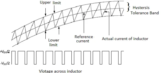
III.HYSTERESIS CURRENT CONTROLLER
Hysteresis current control method of generating the switching signal for the inverter switches in order to control the inverter output current. It is adopted in shunt active filter due to best among other current control methods, easy implementation and quick current controllability. It is basically a fed back current control method, where the actual current continuously tracks the reference current in the hysteresis band .the actual current with in this hysteresis band. The reference and actual current is compared with respect to hysteresis band which decides switching pulse of voltage source inverter.
As the current crosses a set hysteresis band, the upper switch in the half-bridge is turned off and the lower switch is turned on. As the current exceeds the lower band limit, the upper switch is turned on and the lower switch is turned off.
Fig 4.Hysteresis Band and Generation of Pulses
ISSN (Print) : 2320 – 3765 ISSN (Online): 2278 – 8875
I
nternational
J
ournal of
A
dvanced
R
esearch in
E
lectrical,
E
lectronics and
I
nstrumentation
E
ngineering
(An ISO 3297: 2007 Certified Organization)
Vol. 3, Issue 12, December 2014
IV.SIMULATION RESULTS
Fig.5 MATLAB/SIMULINK model of PV interactive SAPF
Fig.5 The proposed model for a PV interactive shunt active power filter using harmonic detection method with hysteresis current controller has been successfully modelled and tested using MATLAB/SIMULINK toolbox
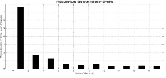
Fig. 6 Distorted current at source without compensation
Fig.7 FFT analysis for above fig 6 distorted current
Fig. 8 compensating currents injected by the active power filter
Fig 8 the compensating currents injected by the shunt active power filter at the point of common coupling.
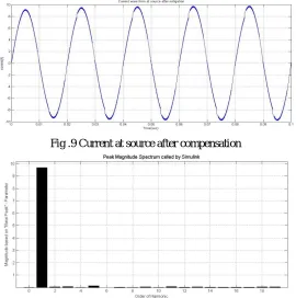
Fig .9 Current at source after compensation
Fig .10 FFT analyses for above fig 9 distorted current
ISSN (Print) : 2320 – 3765 ISSN (Online): 2278 – 8875
I
nternational
J
ournal of
A
dvanced
R
esearch in
E
lectrical,
E
lectronics and
I
nstrumentation
E
ngineering
(An ISO 3297: 2007 Certified Organization)
Vol. 3, Issue 12, December 2014
presented for SAPF in single phase circuit. The proposed control algorithm is capable of reducing the harmonics in the limits of IEEE 519. After compensation, the source current is sinusoidal. It compensates harmonics present in the power system and the percentage of current THD values is reduced and reactive power will decreased and power factor will be improve.
REFERENCES
[1]. Lei Xiao, GuoChunlin, XuYongha “Study on Harmonic and Reactive Current Detection in Single-Phase Circuit” International Conference on Measuring Technology and Mechatronics Automation IEEE may 2009.
[2].JinweiHe,YunWei Li and FredeBlaabjerg “Active Harmonic Filtering Using Current-Controlled, Grid-Connected Dg Units With Closed-Loop Power Control” IEEE Transactions On Power Electronics, Vol. 29, No. 2, February 2014.
[3].Hirofumi Akagi, Yoshihirakanazawa and AkiraNabae“ Instantaneous Reactive Power Compensators Comprising Switching Devices Without Energy Storage Components”, IEEE transactions on industry applications, vol. Ia-20, no. 3, may/june 1984.