Design of Microstrip Patch Antenna with
Koch Snowflake Geometry for Multiband
Applications
Nayna S. Dandgavhal1, Prof. M.B. Kadu2, Prof. R. P. Labade3
PG Student, Dept. of E&TC, AVCOE, Sangamner, Maharashtra, India
Professor, Dept. of E&TC, AVCOE, Sangamner, Maharashtra, India2
HOD, Dept. of E&TC, AVCOE, Sangamner, Maharashtra, India3
ABSTRACT: This paper presents the design and simulation of Koch Snowflake Fractal antenna up to second iteration.
The Koch snowflake antenna is used for size reduction. Due to the self similar and space-filling property of fractal geometry, antenna operates at lower resonant frequency. From the results it is observed that, as the iteration and the iteration factor increases, the resonant frequency of the antenna shifted to lower frequency. For design and simulation of antenna CAD-FEKO - 6.3 software is used. Koch Snowflake Fractal antenna helps in fitting large electrical lengths into small volume. FR4 substrate having dielectric constant - 4.4 is used for designing the antenna and is fed with 50 ohms coaxial line. By optimizing the coaxial feed and its location the antenna has been optimized to operate at multiple frequencies 1.24 GHz for GPS application, 1.42 for L-band applications and 2.92 GHz for S-band applications.
KEYWORDS:CAD FEKO -6.3, Co-axial feed, Koch Snowflake Fractal antenna, .
I.INTRODUCTION
Nowadays due to tremendous development in both the military as well as the commercial area, there is great demand for antenna design that possesses some highly desirable features such as compact size, low profile, conformal and multiband or broadband. There are a variety of approaches that have been developed over that year, which can be utilized to achieve one or more of these design objectives. The fractal geometry plays an important role for achieving these requirements. Basically fractal means, broken or irregular fragment. Fractal was first defined by Benoit Mandelbrot in 1975 as a way of classifying structures whose dimensions were not whole numbers. A fractal is a rough or fragmented geometric shape that can be subdivided in parts, each of which is (at least approximately) a reduced-size copy of the whole. In nature there are many mathematical structures that are fractals; such as clouds, mountains, turbulence, and coastlines that do not correspond to simple geometric shapes. The use of fractal geometry is a very good solution to reduce the size of antenna. Fractal shaped antennas show some interesting features which results from their geometrical properties. Self similarity and space filling properties are the unique features of fractals which enable the realization of antennas having some interesting characteristics such as multi-band operation and miniaturization.
II. GEOMETRY OF KOCH SNOWFLAKE
The Koch curve is a mathematical curve and is a initial fractal curve. The construction of the Koch fractal starts with a straight segment having length L (Initiator), then this line segment is divided into three parts of equal length i.e. L/3 each, and next the middle segment is replaced with other two segments of the same length, with 60 degree as intersection angle. This is called as the Generator and is the first iterated version of geometry. By using this process further, higher iterations are generated.
III. ANTENNA DESIGN
A. Design of Basic Triangular Patch
Here CAD FEKO-6.3 software is used to design the Koch antenna. The Koch snowflake is constructed first by starting with a simple equilateral triangular patch as shown in Fig 1(a) .
(a) (b) (c) (d) Fig.1. Basic Steps construction of a Koch snowflake fractal
(a) Basic Triangular Patch geometry, (b) First iteration, (c) Second iteration (d) Third iteration
For the design of triangular patch antenna there are three important parameters i.e. resonant frequency (fr), dielectric material of the substrate ( ), and the thickness of the substrate (D). The resonant frequency chosen here is 1.6 GHz. FR-4 is the dielectric material selected for this design having a dielectric constant ( ) of 4.4.
The fundamental mode resonant frequency of such antenna is given as follows:
=
√
(1)
Where,
C = Speed of light
= Relative permittivity of substrate
=
√ (2)
The patch side length (a) of triangle is given as follows:
=
C. Design of Second Iteration of Koch Fractal
After second iteration of the Koch fractal antenna, the resulting shape is as shown in Fig. 1 (c) .It is observe that in each new iteration the area of the geometry increases .Let be the area at iteration ,then the area of the next iteration can be computed as:
Where a is the side length of initial triangle that has an area of ,
IV. SIMULATION RESULTS AND DISCUSSION
The simulation tool used for evaluating the performance of the Koch fractal antenna is CAD-FEKO 6.3 software, which is based on the method of moment’s technique and used for computing VSWR, Return Loss and Gain.
A. Simulation Result for Basic TMSA (Iteration -0)
The structure of basic TMSA (Iteration-0) is shown in Fig. 2 and on simulating the structure with the help of
CAD
FEKO -6.3
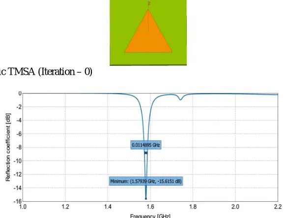
; the following results wereobtained,Fig. 2 Structure of basic TMSA (Iteration – 0)
Fig. 3 Return loss of basic TMSA (Iteration – 0)
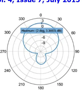
Fig. 4 E-plane radiation pattern of basic TMSA (Iteration – 0)
Above fig. 3 shows return loss of basic TMSA. The triangular patch resonates at the frequency 1.57 GHz having bandwidth 25.25 MHz with a return loss of -15.61 dB and fig.4 shows the directional radiation pattern of the basic TMSA with 3.42 db gain.
B. Simulation Result for Iteration -1
Fig. 5 Iteration -1 of Koch snowflake Fractal Antenna
Fig. 7 Iteration – 1 of Koch snowflake fractal antenna E-plane radiation pattern
Above Fig. 5 shows the structure of Koch snowflake fractal antenna with first iteration and on simulating the above structure with the help of CAD FEKO software we get return loss as shown in fig 6. In which antenna resonate at 1.4 GHz frequency with 20.04 MHz bandwidth and -20.2 db return loss. Fig. 7 shows E-plane directional radiation pattern of iteration-1 with improved gain of 4.95 db.
C. Simulation Result for Iteration -2
Fig. 8 Iteration -2 of Koch snowflake Fractal Antenna
1
Fig. 10 Iteration -1 of Koch snowflake Fractal Antenna E-plane radiation pattern
After simulating the structure of iteration -2 of Koch snowflake fractal antenna we get simulated return loss and E-plane radiation pattern as shown in fig 8 & fig. 9 respectively. This shows that antenna can resonate at three different resonant frequencies 1.24 GHz, 1.42 GHz and 2.91 GHz with 7.88 MHz, 10.43 MHz and 41.22 MHz bandwidth respectively. E-plane radiation pattern as shown in fig.10 shows decrease in gain of the antenna due to addition of multiple frequencies.
The Table1 gives all the summarized results of the three proposed antennas.
Table 1: Iteration wise results of Koch Fractal Antenna
Types of Microstrip Antenna Frequency (GHz) Bandwidth (MHz) Return
Loss(dB) VSWR Gain(dB)
Impedance (Ohm)
Triangular
Microstrip Antenna 1.57 25.25 -15.61 1.39 3.42 47.12
Iteration - 1 of koch snowflake fractal
antenna
1.4 20.04 -20.2 1.27 4.95 42.54
Iteration – 2 of koch snowflake fractal
antenna
1.24 7.88 -11.91 1.67
3.36
53.9
1.42 10.43 -19.17 1.24 47.83
2.91 41.22 -11.9 1.68 53.12
From above table it is clear that when iteration increases, the resonant frequency of this triangular patch antenna shifted to lower side and in second iteration we triple frequency band with large bandwidth.
and operate at desired frequency 1.24 GHz for GPS (Global Position Systems) applications, 1.42GHz for L-band applications & 2.92 GHz for S-band applications.
REFERENCES
[1] Rajeev Mathur, Sunil Joshi, Krishna C Roy, “A Novel multiband koch loop antenna using fractal geometry for wireless communication system ” International Journal of Wireless & Mobile Networks (IJWMN) Vol. 3, No. 5, October 2011K.
[2]Solanki Neha A., Piyush C. Dalsania, Hiren J. Kathiriya, “ Analysis of Koch Snowflake Fractal Antenna for Multiband Application,” International Journal of Engineering Research & Technology (IJERT).
[3]V.V.Khairnar, K. R.Khandagle, Abhilasha Mishra,“Design and Implementation of Dual Frequency Microstrip Patch Antenna with Koch Fractal Geometry using co-axial Feeding Technique,” International Journal of Engineering, Economics and Management ISSN: 2319-7927, Volume 1, Issue 3.
[4] Prajakta B.Jadhav and Mrs. M. M. Pawar “Bandwidth and Gain improvement by using suspended Fractal MSA at 2.4GHZ IOSR Journal of Electronics and Communication Engineering (IOSR-JECE) e-ISSN: 2278-2834,p- ISSN: 2278-8735.Volume 9, Issue 4, Ver. V (Jul - Aug. 2014), [5] B.T.P. Madhav, D.Ujawala, J. Ravindranath Chowdary, “Design and Analysis of New Sierpinski Carpet Fractal Antenna” May-June 2013. [6]Rahul Batra and Prof. P. L. Zade, "Design Sierpinski Carpet Fractal Antenna for Wireless Communication", International Conference on VLSI, Communication and Networks (VCAN-2011), Alwar, Rajasthan, India