Integrated Control Methods for Charging and Discharging of Battery
System in Wind Energy Conversion System for an Isolated BTS
P.Bhagya Sree1, Mr.B.Subhash2 1
M.Tech student, PEES, S.R. Engineering College,India 2
Sr.Asst.Professor,EEE, S.R. Engineering College , India
Abstract: Energy demand across the world is increasing and the resources are becoming limited. The main source of power is from the conventional sources only. Some of the conventional sources of energies like thermal energy is formed from the fossil fuel coal which are diminishing and is only restricted to 2030. Renewable sources of energies are Solar, Wind, Biomass, etc hold bright prospect for the future. Wind industry has made quickprogresses in the recent years. In order to ensure continuous supply of power suitable storage technology is used as backup. In this paper, the sustainability of a 4-kW hybrid of wind and battery system is inspected for meeting the necessities of a 3-kW stand-alone dc load representing a base telecom station. A charge controller for battery bank based on turbine maximum power point tracking and battery state of charge is developed to ensure controlled charging and discharging of battery. The mechanical safety of the WECS is assured by means of pitch control technique. Both the control schemes are integrated and the efficiency is validated by testing it with various load and wind profiles in MATLAB/SIMULNIK.
Index Terms—Maximum power point tracking (MPPT), pitch control, state of charge (SoC), and wind energy conversion system (WECS) regulator.
I. INTRODUCTION
The continuously increasing energy demand, along with the necessity of higherreliability requirements, are driving the modern power systems towards distributedgeneration (DG) as an alternative source. Wind turbines, Fuel cells (FC), Photovoltaic(PV), Batteries, etc. are nowadays the most common available DGs for generation ofpower mostly in peak times or in rural area. Microgrids are combinations of DGs andload. To deliver high quality and reliable power, the microgrid should appear as asingle controllable unit that responds to changes in the system. Microgrids shouldpreferably tie to the utility grid so that any surplus energy generated within them canbe channelled to the grid. Similarly, any shortfall can be replenished from the grid. Asfar as microgrid is concerned the loads may be unbalanced and non-linear in nature.Hence, microgrid should not inject harmonic and unbalanced currents into the grid.Harmonic currents and negative sequence currents (due to
unbalance) willunnecessary increase the line currents flowing between microgrid and grid.If wind power exceeds the load demand, the surplus can be stored in the batteries [1]. The function of an electrical generator is providing a means for energy conversion between the mechanical torque from the wind rotor turbine, as the prime mover, and the local load or the electric grid.For the installation of wind energy MNRE scheme (The Ministry of New & Renewable energy) has introduced to aware more and more people about this technology, government also gives incentives in order to promote wind energy. Wind is air in motion; this is actually derived from solar energy. About 2% of total solar flux that reaches the earth’s surface is transformed into wind energy due to uneven heating of atmosphere. This kinetic energy of wind is used to gain the rotational motion of wind turbine which is coupled with an electrical generator to supply over a region acting as standalone or supplying power to a grid. An actual WECS (Wind energy conversion system) be considered as follow [1] which can be used in two different ways: Isolated standalone systemand Grid
connected systemFigure 1 shows Isolated
Standalone system which is used to provide energy to small scale industries or towns located in remote areas.
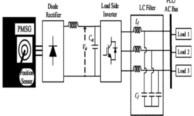
Fig. 1.Standalone wind energy system.
II. RELATED WORK
A detailed comparison between asynchronous and synchronous generators for wind farm application is made in [4]. The major advantage of asynchronous machine is that the variable speed operation allows extracting maximum power from WECS and reducing the torque fluctuations [5]. Induction generator with a lower unit cost, inherent robustness, and operational simplicity is considered as the most viable option as wind turbine generator (WTG) for off grid applications [6].
However, the induction generator requires
capacitor banks for excitation at isolated locations.
The excitation phenomenon of self-excited
induction generator (SEIG) is explained in [5]–[7]. The power output of the SEIG depends on the wind flow which by nature is erratic. Both amplitude and frequency of the SEIG voltage vary with wind speed. Such arbitrarily varying voltage when interfaced directly with the load can give rise to flicker and instability at the load end. So, the WECS are integrated with the load by power electronic converters in order to ensure a regulated load voltage [8].
III. HYBRID WIND-BATTERY SYSTEM FOR AN ISOLATED DC LOAD
The proposed hybrid system comprises of a 4-kW WECS and 400 Ah, C/10 lead acid battery bank. The system is designed for a 3-kW stand-alone dc load. The layout of the entire system along with the control strategy is shown in Fig. 1.
IV. CONTROL STRATEGY FOR STAND-ALONE HYBRID WIND-BATTERY SYSTEM
The wind flow is erratic in nature. Therefore, a WECS is integrated with the load by means of an ac–dc–dc converter to avoid voltage flicker and harmonic generation. The control scheme for a stand-alone hybrid wind-battery system includes the charge controller circuit for battery banks and pitch control logic to ensure WT operation within the rated value. The control logic ensures effective control of the WECS against all possible disturbances.
A. Charge Controller for the Battery Bank
The development of charge controller circuit for a 400 Ah, C/10 battery bank using a dc–dc buck converter in MATLAB/SIMULINK platform. Generally, the batteries are charged at C/20, C/10, or C/5 rates depending on the manufacturer’s specification where C specifies the Ah rating of battery banks. So, the battery bank system considered in the design can be charged at 20, 40, or 80 A. But, in this paper, C/10 rate (i.e., 40 A) for battery charging is chosen. However, the current required for charging the battery bank depends on the battery SoC.
B. Control Strategy
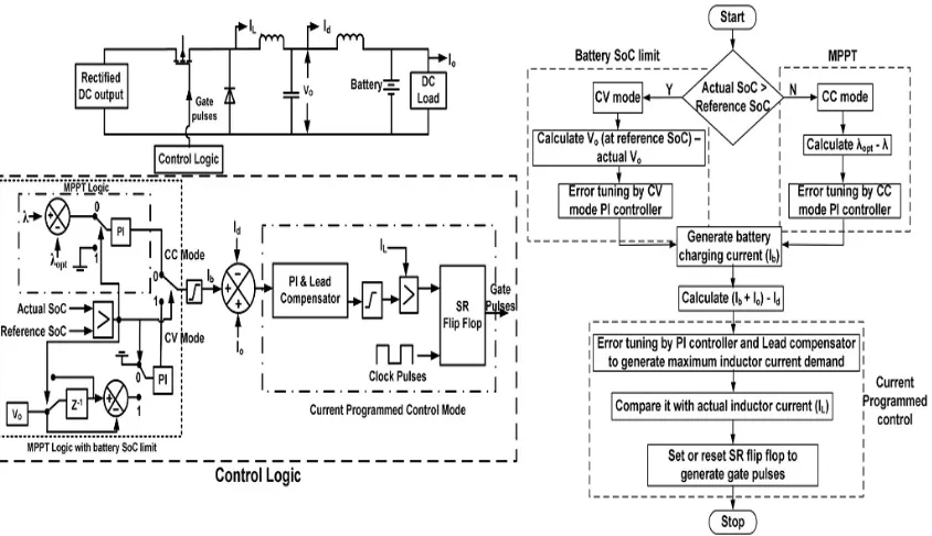
The implementation of the charge control logic as shown in Fig. 2 is carried out by three nested control loops. The outer most control loop operates the turbine following MPPT logic with battery SoC limit. To implement the MPPT logic, the actual tip speed ratio (TSR) of turbine is compared with the optimum value. The error is tuned by a PI controller to generate the battery current demand as long as the battery SoC is below the CC mode limit. Beyond this point, the SoC control logic tries to maintain constant battery charging voltage.
This in turn reduces the battery current demand and thus prevents the battery bank from overcharging. The buck converter inductor current command is generated in the intermediate control loop. To design the controller, it is essential to model the response of the battery current (Ib) with respect to
the inductor current (IL).
The transfer function can be computed from Fig. 3 and is given by
( )
( )=
+ 1
+ ( + + ) + 1… … … 1
Fig. 1.Layout of hybrid wind–battery system for a stand-alone dc load.
Fig. 2. Block schematic and flowchart of the charge controller circuit for battery.
For regulating the peak-to-peak (p–p) ripple of battery current and converter output voltage within 2% of the rated value the L and C are calculated to be 10 mH and 5 mF, respectively.
Fig. 3.Circuit representation of buck converter output.
V. MODES OF BATTERY
CHARGING
A. CC Mode of Battery Charging
In CC mode, the battery charging current demand is determined from the MPPT logic. MPPT is implemented by comparing the actual and optimum TSR (λopt). The error is tuned by a PI controller to
wind speed. In this mode, the converter output voltage rises with time while the MPPT logic tries to transfer as much power as possible to charge the batteries. The actual battery charging current that can be achieved does not remain constant but varies with available wind speed subject to a maximum of C/10 rating of the battery. The battery charging current command has a minimum limit of zero. In case the wind speed is insufficient to supply the load even with zero battery charging current the inductor current reference is frozen at that particular value and the balance load current is supplied by the battery.
B. CV Mode of Battery Charging
In the CC mode, the battery voltage and SoC rise fast with time. However, the charge controller should not overcharge the batteries to avoid gasification of electrolyte [14]. As a result, once the battery SoC becomes equal to the reference SoC the controller must switch over from CC mode to CV mode. In CV mode, the battery charging voltage is determined from the buck converter output voltage (Vo).
C. Pitch Control Mechanism
If the WT is allowed to operate over the entire range of wind speed without implementation of any control mechanism, the angular speed of the shaft exceeds its rated value which may lead to damage of the blades. So, it is very much essential to control the speed and power at wind speeds above the rated wind speed. This is achieved by changing the pitch angle of the blade. Such a mechanism is referred to as the pitch control of WT.
D. Pitch Control Scheme
The pitch control scheme is shown in Fig. 7. As seen the p.u. value of each input is compared with 1 to calculate the error. The errors are tuned by PI controller. The “MAX” block chooses the maximum output from each PI controller which is then passed on to a limiter to generate the pitch command for the WT.
VI. EXPERIMENTAL RESULTS
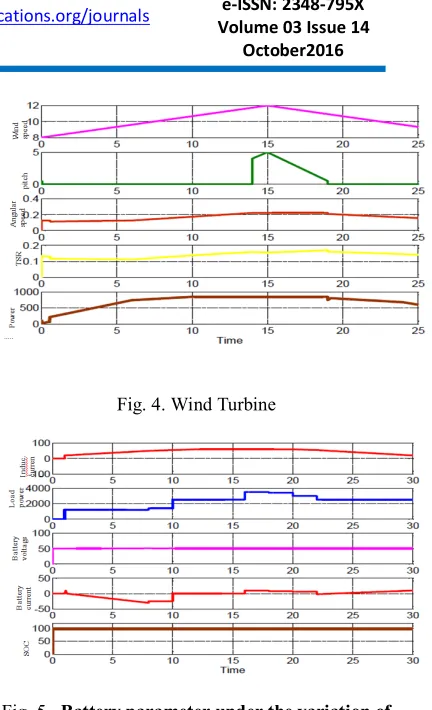
Fig. 4. Wind Turbine
Fig. 5. Battery parameter under the variation of wind speed
VII. CONCLUSION
In this paper, a hybrid wind-battery system is chosen to supply the desired load power. To mitigate the random characteristics of wind flow the WECS is interfaced with the load by suitable controllers. The control logic implemented in the hybrid set up includes the charge control of battery bank using MPPT and pitch control of the WT for assuring electrical and mechanical safety. The charge controller tracks the maximum power available to charge the battery bank in a controlled manner. The hybrid wind-battery system along
with its control logic is developed in
MATLAB/SIMULINK and is tested with various wind profiles. The outcome of the simulation experiments validates the improved performance of the system.
REFERENCES
[1] The Modeling and Simulation of Wind Energy
Based Power System using MATLAB.
and Energy Management, ISSN (PRINT): 2231-4407, Volume -1, Issue-2, 2011.
[2] R. D. Richardson and G. M. Mcnerney, “Wind energy systems,” Proc. IEEE, vol. 81, no. 3, pp. 378–389, Mar. 1993.
[3] R. Saidur, M. R. Islam, N. A. Rahim, and K. H. Solangi, “A review on global wind energy policy,” Renewable Sustainable Energy Rev., vol. 14, no. 7, pp. 1744–1762, Sep. 2010.
[4] M. T. Ameli, S. Moslehpur, and A. Mirzale, “Feasibility study for replacing asynchronous generators with synchronous generators in wind farm power stations,” in Proc. IAJC – IJME, Int. Conf. Eng. Technol., Music City Sheraton, Nashville, TN, US, ENT paper 129Nov. 17–19, 2008.
[5] G. K. Singh, “Self excited generator research— A survey,” Electric Power Syst. Res., vol. 69, no. 2/3, pp. 107–114, 2004.
[6] R. C. Bansal, “Three-phase self-excited induction generators: An overview,” IEEE Trans. Energy Convers., vol. 20, no. 2, pp. 292–299, Jun. 2005.
[7] S. C. Tripathy, M. Kalantar, and N. D. Rao, “Wind turbine driven self-excited induction generator,” Energy Convers. Manag.vol. 34, no. 8, pp. 641–648, 1993.
[8] A. Chakraborty, “Advancements in power electronics and drives in interface with growing
renewable energy resources,” Renewable
Sustainable Energy Rev., vol. 15, no. 4, pp. 1816– 1827, May 2011.
[9] Y. Y. Xia J. E. Fletcher S. J. Finney K. H. Ahmed B. W. Williams,”Torqueripple analysis and reduction for wind energy Conversions systems usinguncontrolled rectifier and Boost converter”, IET Renew. Power Gener., 2011,vol. 5, iss. 5, pp. 377-381.
[10] DeBattista, H., Puleston, P. F., Mantz, R. J., Christiansen, C. F.:‘Sliding modecontrol of wind energy systems with DOIG – power efficiency and torsionaldynamics optimization’, IEEE Trans. Power Syst., 2000, vol. iss. 2, pp. 728–734
[11] Pena, R., Clare, J. C., Asher, G. M.,”Doubly fed induction generator using backto back PWM converters and its application to variable speed wind energygeneration”, IET Power Electronics. Appl, 1996, vol. 143, iss.3, pp. 231-241[12] M. Stiebler,”Wind Energy Systems for Electric.Power Generation.”SpringerVerlag Berlin Heidelberg, 2008.
[13] S. Heier,”Grid Integration of Wind Energy Conversion Systems.”© John Wileyand sons.
[14] A. Grauers,”Design of direct-driven
permanent-magnet generators for
windturbines,”School of Electrical and Computer Engineering, Chalmers Universityof Technology, 1996.
[15] C. J. A. Versteegh,”Design of the Zephyros Z 72 Wind Turbine with Emphasison the Direct Drive PM Generator,”in Nordic Workshop on Power and Ind.Electro. (NORPIE), Trondheim, 2004, pp. 14-16.
Authors:
P.Bhagya Sreepursing M.Tech in PEES from Sr Engineering College,Warangal,Telangana,India.