ISSN (Print) : 2320 – 3765 ISSN (Online): 2278 – 8875
I
nternational
J
ournal of
A
dvanced
R
esearch in
E
lectrical,
E
lectronics and
I
nstrumentation
E
ngineering
(An UGC Approved Journal)
Website: www.ijareeie.com
Vol. 6, Issue 9, September 2017
Single Phase Grid-Connected Inverter for PV
System with MPPT
Nikhita Kadam 1 , Prof. A. P. Kinge2
PG Student [Power System], Dept. of Electrical Engineering, Tssm's Bhivarabai Sawant College of Engineering &
Research Narhe, Pune, India1
Professor, Dept. of Electrical Engineering, Tssm's Bhivarabai Sawant College of Engineering & Research Narhe,
Pune, India2
Abstract: Solar energy is a very large, inexhaustible source of energy. The Renewable Energy as a source is focused to bring the awareness towards the Green Energy System which provides the pollution free environment. Also it has no heavy mechanical section and is free from noise. The power from the sun intercepted by the earth is approximately 1.8X10¹¹MW, which is many thousands of times larger than the present consumption rate on the earth of all commercial energy sources. Solar tracking system which can be used as a power generating method from sunlight. This method of power generation is simple and is taken from natural resource. This needs only maximum sunlight to generate power. This project presents for power generation and MPPt solar charging system to utilize the maximum solar energy through solar panel by setting the equipment to get maximum sunlight automatically.. The proposed method is to design an electronic circuit to sense the intensity of light and construct a Buck-Boost converter for to step-up and step-down the voltage, and store the maximum utilized output voltage in Lead-Acid Battery.
I. INTRODUCTION
RECENTLY, the World Wildlife Fund envisioned that the rate of transition to renewable energy will reach 100% by 2050. Report also warns that only through the use of renewable energy can mankind be spared the worst possible scenario resulting from climate change. In other words, renewable energy should not be considered as an option but an integral factor in future development. Furthermore, to preserve the future of national industries, the commissioning of stable large-scale power plants such as thermoelectric or nuclear power plants is crucial for meeting increased power demand.
Considering this requirement, the markets of grid-connected photovoltaic (PV) inverters for industries and power plants are expanding, and large-scale PV power plants have become dominant, generating from several megawatts to several hundred megawatts of electricity. Large-scale PV inverters are connected to different grids according to regulations such as those related to capacity and voltage in each country. However, to increase the efficiency of overall power facilities, they are directly connected to a medium-voltage (MV) grid of over 20 kV.
ISSN (Print) : 2320 – 3765 ISSN (Online): 2278 – 8875
I
nternational
J
ournal of
A
dvanced
R
esearch in
E
lectrical,
E
lectronics and
I
nstrumentation
E
ngineering
(An UGC Approved Journal)
Website: www.ijareeie.com
Vol. 6, Issue 9, September 2017
Basic concept for grid connected inverter through transformer
Fig 1. Basic block diagram of grid feeding inverter through transformer.
Grid-connected photovoltaic (PV) systems often include a line transformer between the power converter and the grid. The transformer guarantees galvanic isolation between the grid and the PV systems, thus fulfilling safety standards. Furthermore, it ensures that no direct current (dc) is injected to the grid. However, the low-frequency (50 or 60 Hz) transformer is bulky, heavy, and expensive and its power loss brings down the overall system efficiency. To eliminate the transformer and to achieve cost, size, and weight reduction as well as efficiency improvement, the research and interest on “transformerless” power conversion is growing.
II. LITERATURE SURVEY
Various techniques of transformer less photovoltaic inverters are:
1. A Transformer less Grid-Connected Photovoltaic System Based on the Coupled Inductor Single-Stage Boost Three-Phase Inverter
2. Pulse width modulation techniques for three phase grid connected inverter.
3. Transformer-Less Grid Feeding Current Source Inverter for Solar Photovoltaic System
1. Transformer less grid-connected PV system based on CL-SSBI
A coupled inductor single-stage boost inverter (CL-SSBI) is introduced an impedance network, including coupled inductor in the front-end of the inverter bridge. The converter uses shoot-through zero vectors to store and transfer energy within the unique impedance network, to step up the bus voltage. Turns ratio of he coupled inductor within the impedance network can also be designed to improve the boost gain. So the ac output voltage can be regulated in a wide range and can be stepped up to a higher value. Higher power loss and
Lower efficiency would be unavoidable if higher boost gain is required, which is the disadvantage of inverters of this type. As shoot-through zero vectors evenly distributed among the three phase legs during a switching period, the equivalent switching frequency viewed from the impedance network can be six times the switching frequency of the inverter bridge, which will greatly reduce the power density and cost of the inverter.
ISSN (Print) : 2320 – 3765 ISSN (Online): 2278 – 8875
I
nternational
J
ournal of
A
dvanced
R
esearch in
E
lectrical,
E
lectronics and
I
nstrumentation
E
ngineering
(An UGC Approved Journal)
Website: www.ijareeie.com
Vol. 6, Issue 9, September 2017
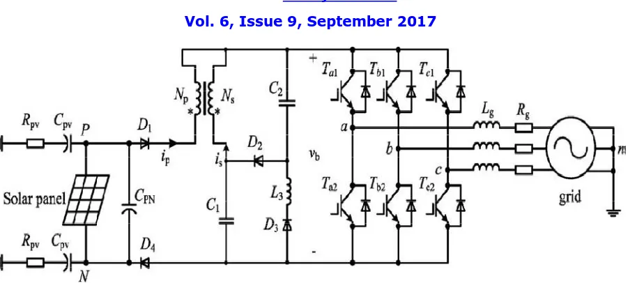
Fig 2 Transformer less grid-connected PV system based on CL-SSBI
2 Pulse width modulation techniques for three phase grid connected inverter.
In order to eliminate the common-mode (CM) leakage current in the transformer less photovoltaic (PV) systems, the concept of the virtual dc bus is used. By connecting the grid neutral line directly to the negative pole of the dc bus, the stray capacitance between the PV panels and the ground is bypassed. As a result, the CM ground leakage current can be suppressed completely. Meanwhile, the virtual dc bus is created to provide the negative voltage level for the negative ac grid current generation. Consequently, the required dc bus voltage is still the same as that of the full-bridge inverter. Based on this concept, a novel transformer less inverter topology is derived, in which the virtual dc bus is realized with the switched capacitor technology. It consists of only five power switches, two capacitors, and a single filter inductor. Therefore, the power electronics cost can be curtailed. This advanced topology can be modulated with the unipolar sinusoidal pulse width modulation (SPWM) and the double frequency SPWM to reduce the output current ripple. As a result, a smaller filter inductor can be used to reduce the size and magnetic losses.
2. Virtual Dc Bus Concept
With respect to the ground point N, the voltage at midpoint B is either zero or +Vdc, according to the state of the switch bridge. The purpose of introducing the virtual dc bus is to generate the negative output voltage, which is necessary for the operation of the inverter. If a proper method is designed to transfer the energy between the real bus and the virtual bus, the voltage across the virtual bus can be kept the same as the real one. As shown in Fig. 2.4, the positive pole of the virtual bus is connected to the ground point N, so that the voltage at the midpoint C is either zero or −Vdc. The dotted line in the figure indicates that this connection may be realized directly by a wire or indirectly by a power switch. With points B and C joined together by a smart selecting switch, the voltage at point A can be of three different voltage levels, namely +Vdc, zero, and −Vdc. Since the CM current is eliminated naturally by the structure of the circuit, there is not any limitation on the modulation strategy, which means that the advanced modulation technologies such as the unipolar SPWM or the double-frequency SPWM can be used to satisfy various PV applications.
ISSN (Print) : 2320 – 3765 ISSN (Online): 2278 – 8875
I
nternational
J
ournal of
A
dvanced
R
esearch in
E
lectrical,
E
lectronics and
I
nstrumentation
E
ngineering
(An UGC Approved Journal)
Website: www.ijareeie.com
Vol. 6, Issue 9, September 2017
A. Double-Frequency SPWM
The topology can also work with double-frequency SPWM to achieve a higher equivalent switching frequency, as shown in Fig. 2.6. In the double-frequency SPWM, the five power switches are separated into two parts, and are modulated with two inverse sinusoidal waves respectively. S1, S2 , and S3 are modulated with ug1, while S4 and S5 are modulated with ug2.
During the positive half grid cycle, the circuit rotates in the sequence of “state 4 – state 1 – state 2 – state 1,” and the output voltage vAN varies between +Vdc and the zero with twice of the carrier frequency. During the negative half grid cycle, the circuit rotates in the sequence of “state 4 – state 3 – state 2 – state 3,” and the output voltage vAN varies between −Vdc and zero.
The aforementioned two modulation strategies both have their own advantages. The double-frequency SPWM can provide a higher equivalent switching frequency so that the size and weight of the filter inductor can be reduced. On the other hand, the unipolar SPWM can guarantee that the virtual dc bus C2 is charged by the real bus every switching cycle, so that the current stress on S1 and S3 caused by the operation of the switched capacitor can be reduced. In this paper, the unipolar SPWM is chosen as an example for the performance evaluation and experimental verification.
3 Transformer-Less Grid Feeding Current Source Inverter for Solar Photovoltaic System
In current source inverter (CSI) topology, dc-link inductor limits the ripple in dc current to a low value. Therefore, current supplied/absorbed by the capacitor has less ripple due to additional current smoothing action of the dc-link inductor. Therefore, CSI requires smaller dc-link capacitor, thereby facilitating the use of highly reliable capacitor. Therefore, current source based solar inverters will have longer operational life as compared to voltage source
based solar inverters. In addition to high reliability, solar inverter should also have high efficiency of power conversion. Typically, solar PV string voltages are small; therefore, additional dc-dc boost converter or ac transformer is used along with VSI. However, CSI has integrated boost functionality and therefore does not require an additional component for voltage boosting. Comparison of the efficiencies of VSI and CSI topologies is reported in summary, CSI offers high reliability at almost the same efficiency as compared to that of voltage source based solar inverter. Another issue related to reducing the size of dc capacitor is the efficacy of maximum power point tracking (MPPT). As dc capacitor value is reduced in VSI, high (switching) frequency voltage ripple on the dc bus voltage increases, thereby reducing the MPPT efficacy. However, in case of CSI, both dc-link inductor and dc-link capacitor collectively determine the ripple in dc voltage. Therefore, low value of voltage ripple can be achieved by suitable selection of dc inductor. Thus, low capacitance values in CSI do not affect the MPPT.
Conventional three-phase PWM-CSI requires an intermediate isolation transformer to feed power to the grid. The use of this transformer reduces the efficiency of conversion by about 2–3%. Furthermore, it increases the size, cost, and weight of inverter, making it unviable for module integrated or string inverter applications. It is recommended to use of a common mode choke
in the dc-link. In addition, a modified PWM strategy is also suggested. However, the strategy does not completely eliminate the common mode voltage. Therefore, this topology is suitable for module integrated inverters (low power), wherein parasitic capacitance is small and therefore the leakage current. However, for string inverter application, wherein various modules are connected to a single inverter, small common mode voltage can inject significant leakage current. To address the aforementioned limitations, a modified CSI is proposed in this paper. It eliminates the high-frequency component in the common mode voltage, thereby suppressing the common mode earth leakage current.
III. PROPOSED TOPOLOGY
PV based Grid control using MPPT
ISSN (Print) : 2320 – 3765 ISSN (Online): 2278 – 8875
I
nternational
J
ournal of
A
dvanced
R
esearch in
E
lectrical,
E
lectronics and
I
nstrumentation
E
ngineering
(An UGC Approved Journal)
Website: www.ijareeie.com
Vol. 6, Issue 9, September 2017
ISSN (Print) : 2320 – 3765 ISSN (Online): 2278 – 8875
I
nternational
J
ournal of
A
dvanced
R
esearch in
E
lectrical,
E
lectronics and
I
nstrumentation
E
ngineering
(An UGC Approved Journal)
Website: www.ijareeie.com
Vol. 6, Issue 9, September 2017
IV. CONCLUSION
This paper recommends the use of current source based solar inverters to improve the reliability as compared to voltage source based inverters. It is shown that conventional CSI injects much higher earth leakage current than that recommended by the standards. To address this limitation, split capacitor based
CSI can be used. Due to the connection of neutral to the midpoint of split capacitor arrangement across the PV array, undesired current flows through the C–L filter during the zero state. To address this issue, two reverse blocking semiconductor switches are used as the fourth leg of CSI.
REFERENCES
[1] Yufei Zhou, Wenxin Huang, Ping Zhao and Jianwu Zhao “A Transformerless Grid-Connected Photovoltaic System Based on the Coupled Inductor Single-Stage Boost Three-Phase Inverter”, IEEE transactions on power electronics, vol. 29, no. 3, march 2014.
[2] Sandeep Anand, Saikrishna Kashyap Gundlapalli, and B. G. Fernandes, “Transformer-Less Grid Feeding Current Source Inverter for Solar Photovoltaic System”, IEEE transactions on industrial electronics, vol. 61, no. 10, october 2014
[3] Qingzeng Yan, Xiaojie Wu, Xibo Yuan, Yiwen Geng, and Qi Zhang, “Minimization of the DC Component in Transformerless Three-Phase Grid-Connected Photovoltaic Inverters”, IEEE transactions on power electronics, vol. 30, no. 7, july 2015.
[4] Yunjie Gu, Wuhua Li, Yi Zhao, Bo Yang, Chushan Li, and Xiangning He, Fellow“Transformerless Inverter With Virtual DC BusConcept for Cost-Effective Grid-Connected PVPower Systems”, IEEE transactions on power electronics, vol. 28, no. 2, february 2013.