Available online:
https://edupediapublications.org/journals/index.php/IJR/
P a g e | 2141Process Optimization of Spike Support Using Cam Software
1
J.Anudeep,
2K.Kiran Kumar,
3J.Narsaiah
1
M.Tech student,
2Assistant professor,
3Assistant professor. Department of
Mechanical Engineering, Avn Institute of Engineering and Technology, Hyd, T.S
ABSTRACT
In manufacturing, the goal is to produce components that meet the design specifications. The design specification ensures the functionality aspect. Next step to follow is to assemble these
Spike support is used in a fourth generation man-portable fire-andforget anti-tankguidedmissile with tandem charged heat warhead, developed and designed by the Israeli company and in service with a number of nations. As it is a missile component it should be light in weight at the same time strength should be more. Aluminum material is used for spike support due to its best material properties. Due to this thin wall thickness there is more chance of rejections and Reworks.
Nowadays rejection is a serious problem arising in every manufacturing industry. Due to this reason the manufacturing industry is advancing into losses. There are many factors responsible for Rejection and reworks, such as Human errors, machine errors, process planning, material errors etc.CAD/CAM/CAE systems play a vital role in design optimization and process optimization of any component and helpful in reducing the rejections and reworks.
Keeping in view the above important aspect this project has been taken up for reducing the rejections to a minimum. The aim of the project is to reduce and maintain the rejection rate below 6 %which was previously 9% and reduce and maintain the rework rate below 10 %which was previously 15%.
Initially the optimum cutting speed of the tool has been evaluated by doing the harmonic analysis in the CAE system using ANSYS software. Once the cutting speeds are determined, manufacturing process plan will be developed in CAM system using NX-CAM software. Process optimization was also carried out by using the Mandrel for job holding to reduce damage to the component while machining operation is running.
LITERATURE SURVEY
Pollack, 1976
[1]:-A Fixture is a work piece locating and holding device used with machine tools, inspection, welding and assembly; it does not control the position of the tool or instrument which is being used
• Elements of the Jig or Fixture must also be present which Support the work and elements, called locators, which Position the work
• Once located and positioned, the work is Clampedso that it will not move off the supports or locators.
Burley and Corbett, 1998 [2]:-
• A Jig is defined as a manufacturing aid that either holds a part or is itself located on the part and is fitted with devices to guide a cutting tool ensuring the correct location of the machining path relative to the part
• A Fixture is defined as a manufacturing aid for holding and locating parts during machining or assembly operations, which do not provide definite guidance for the cutting tools
• Tooling is used as the generic name for jigs and fixtures and also the tools set from the master gauges for calibrating jigs and fixtures
• Hence, Jig less Assembly is assembly without the use of jigs; it requires that parts are manufactured to sufficient accuracy to ensure correct assembly; it is not necessarily fixtureless [or tool less] assembly.
J. C. Trappey and C. R. Liu 1990 [3]:-
Fixture design can be classified as a part of process planning. The taskwise description of process planning specifically states that "'fixture design for each workpiece set-up" is an integral planning task. However, the automation of fixture design has been overlooked in most research into automated process planning.
Available online:
https://edupediapublications.org/journals/index.php/IJR/
P a g e | 21422. Fixture assembly - constructing and assembling modular fixture components. The orientation of each component on the base plate is determined according to the work piece set-up. Consequently, the assembly sequence of the fixture components is planned for automatic assembly by robot hand. 3. Fixture verification - proving the validity of the fixture configuration with consideration of some operating factors, such as the cutting directions, the acting forces and the machining sequence.
N. P. Maniar, D. P. Vakharia 2013 [4]:-
Fixturing contributes significantly to overall manufacturing cost, it is sometimes neglected for the reason of cost reduction. The design and manufacture of fixtures can be time consuming, and it increases the manufacturing cycle time of any product that needs machining and/or assembly. The main reason is that fixtures are designed to tight tolerances, typically 30-50% of the overallwork piece tolerance.
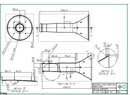
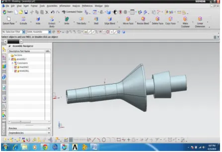
3D MODELING OF SPIKE SUPPORT
Fig. 2D input of spike support
Final 3D model of spike support
Fig. final 3D model of spike support
FINITE ELEMENT ANALYSIS OF SPINDLE
modeling of the spindle unit:
High speed spindle used for HSM setup has the following specifications:
Spindle power - 5 kW Spindle speed - 6,000 rpm The bore diameter - 40mm. Length of the spindle unit - 330mm
Fig. isometric view of the spindle and tool
Modal analysis:
Available online:
https://edupediapublications.org/journals/index.php/IJR/
P a g e | 2143material properties used in the analysis
Boundary Conditions:
Displacements are constrained at the nodes where the spindle is mounted on the front and rear bearings.
Results: The natural frequency of the spindle is listed in the below table
Mode No Natural Frequency (Hz)
1 8.8
2 8.81
3 16.46
4 16.49
5 16.93
6 46.51
7 48.96
8 48.98
9 83.6
10 89.53
Table First 10 Natural frequencies of the spindle
Fig shows mode shape @ 8.8Hz
Fig shows mode shape @ 16.9Hz
Fig shows mode shape @89.53Hz
From the vibration analysis of the high speed spindle unit, it is recommended that the
Material
Young's
Modulus(Mpa)
Density
(Kg/m3)
High speed
steel 2e5 7850
Carbide cutting
tool 5.5e5 1563
Nodes
Available online:
https://edupediapublications.org/journals/index.php/IJR/
P a g e | 2144frequencies listed above should be avoided during machining process.
FINITE ELEMENT ANALYSIS OF SPIKE SUPPORT COMPONENT
Fig Finite element meshed model of the spike support component
Material properties used in the analysis:
Fig Boundary conditions for Modal analysis
Results: The natural frequency of the spindle with corresponding mode shapes is listed in the below table
Mode no Natural frequency (Hz)
1 12.71
2 12.78
3 14.96
4 14.97
5 24.48
6 24.95
7 41.17
8 43.95
9 48.96
10 83.6
Table shows first 10 natural frequencies of the spike support
Mode1@ 12.7 Hz:
Mode5@ 24.48 Hz:
[email protected] Material
Young's
Modulus(Mpa)
Density
(Kg/m3)
Available online:
https://edupediapublications.org/journals/index.php/IJR/
P a g e | 2145HARMONIC ANALYSIS OF THE SPIKE
SUPPORT COMPONENT
Fig shows Segregation of zones based on the thickness of the component.
A harmonically varying load simulating the effect of cutting force for an interrupted face turning operation of magnitude 200 N (cutting force) is applied on the face of the component of the structure in zone-1.
Fig Harmonic Load for zone 1 turning
Harmonic analysis has been carried out in the frequency range of 10-100Hz (600-6000 rpm).
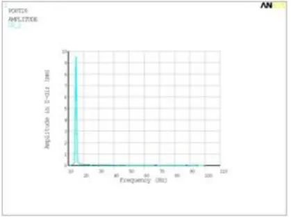
Fig Frequency Vs amplitude in X-dir graph for Zone1
From the above graph it is concluded that the stable speed range is between 20-100Hz i,e (1200-6000 rpm).
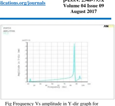
Fig Frequency Vs amplitude in Y-dir graph for Zone1
From the above graph it is concluded that the stable speed range is between 14-24Hz i,e (840-1440 rpm),25-64Hz i,e (1500-3840 rpm)and 70-80Hz i,e (4200-4800 rpm).
Available online:
https://edupediapublications.org/journals/index.php/IJR/
P a g e | 2146From the above graph it is concluded that the stable speed range is between 20-100Hz i,e (1200-6000 rpm).
From the above three graphs is it concluded that the stable speed range for machining the spike support component is 14-24Hz i,e (840-1440 rpm),25-64Hz i,e (1500-3840 rpm)and 70-80Hz i,e (4200-4800 rpm).From the analysis it is concluded that if the spike support component is machined as per the above speed range in the Zone1,then the component will be free of vibrations and good surface finish can be achieved.
CASE-2:
A harmonically varying load simulating the effect of cutting force for an interrupted face turning operation of magnitude 200 N (cutting force) is applied on the face of the component of the structure in zone-2.
Fig Harmonic Load for zone 2 turning
Harmonic analysis has been carried out in the frequency range of 10-100Hz (600-6000 rpm).
Fig Frequency Vs amplitude in X-dir graph for Zone2
From the above graph it is concluded that the stable speed range is between 20-70Hz i,e (1200-4200 rpm)
Fig Frequency Vs amplitude in Y-dir graph for Zone2
From the above graph it is concluded that the stable speed range is between 10-80Hz i,e (600-4800 rpm)
Fig Frequency Vs amplitude in Z-dir graph for Zone2
From the above graph it is concluded that the stable speed range is between 14-80Hz i,e (840-4800 rpm)
Available online:
https://edupediapublications.org/journals/index.php/IJR/
P a g e | 2147CASE-3:
A harmonically varying load simulating the effect of cutting force for an interrupted face turning operation of magnitude 200 N (cutting force) is applied on the face of the component of the structure in zone-3.
Fig Harmonic Load for zone 3 turning
Harmonic analysis has been carried out in the frequency range of 10-100Hz (600-6000 rpm).
Fig Frequency Vs amplitude in X-dir graph for Zone3
From the above graph it is concluded that the stable speed range is between 10-80Hz i,e (600-4800 rpm)
Fig Frequency Vs amplitude in Y-dir graph for Zone3
From the above graph it is concluded that the stable speed range is between 10-30Hz i,e (600-1800 rpm)
Fig Frequency Vs amplitude in Z-dir graph for Zone3
From the above graph it is concluded that the stable speed range is between 10-50Hz i,e (600-3000 rpm).
Available online:
https://edupediapublications.org/journals/index.php/IJR/
P a g e | 2148COMPUTER AIDED MANUFACTURING
From the above finite element analysis it is concluded that the stable speed range for machining the spike support component is 10-30Hz i,e (600-1800 rpm). Maintaining this stable speed spike component is manufactured on CNC machine. The main objective of the project is to reduce rejection and reworks rate.
Methodology used in manufacturing of spike support is as mentioned below:
Identifying suitable machine.
Selecting suitable tools for manufacturing thin walled component.
Designing fixture/mandrel to support spike component for external operations.
Listing down the Sequence of operations performed on spike component.
Generating tool path at specified cutting speed.
Generating NC program using NX-CAM software.
Design of mandrel:
Input 2D Drawing for Mandrel
Fig. 2D input of mandrel
Fig. final 3D model of mandrel
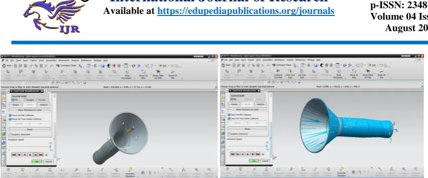
Generating tool path on spike support:
The series of movements made by the tip of a cutting tool. X and Z codes indicate a tool path within a part program. The path through space that the tip of a cutting tool follows on its way to producing the desired geometry of the work piece.
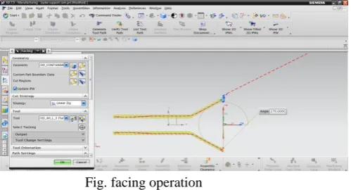
Set_up_1 tool path generation
Below image shows the creation of FACING operation on spike model maintaining speed at 1200rpm and feed 0.25 mmpr.
Fig. facing operation
Below image shows the verification of facing operation
Fig. verification of facing operation
Available online:
https://edupediapublications.org/journals/index.php/IJR/
P a g e | 2149Fig.OD_Rough_Turn operation
Below image shows the verification of OD_ROUGH operation
Fig. verification of OD_Rough_Turn operation
Below image shows the creation of ID_ROUGH operation on spike model maintaining speed at 1200rpm and feed 0.25 mmpr.
Fig. verification of ID_Rough operation
Set_up_2 tool path generation:
Below image shows the creation of FACING operation on spike model maintaining speed at 1200rpm and feed 0.25 mmpr.
Fig. facing operation
Below image shows the verification of facing operation
Fig. verification of facing operation
Below image shows the creation of OD_ROUGH operation on spike model maintaining speed at 1200rpm and feed 0.25 mmpr.
Fig.OD_Rough operation
Available online:
https://edupediapublications.org/journals/index.php/IJR/
P a g e | 2150Fig. verification of drilling operation Fig. Final model
OPERATION LIST BY PROGRAM
PROGRAM NAME : PROGRAM
manufacturing process of spike support on CNC
machine:
Raw material is placed on the machine, and degree of freedom is arrested using fixtures. Facing operation is general operation which will be done for any component, after facing internal operations are done on the spike support
First step: facing operation is done on the raw material
Second step: internal roughing operation done on the component
Third step: the designed mandrel is fixed internally in the spike component and external roughing is done
Fourth step: the component is fixed reversely in the fixture and setup_2 operations are done. Outer roughing operation is done.
Fifth step: drilling operation is done on final turning component.
OPERATION NAME OPERATION DESCRIPTION TOOL NAME
FACING turning/FACING OD_80_L_3
ROUGH_BORE_ID turning/ROUGH_BORE_ID ID_80_L_ROUGH
ROUGH_TURN_OD turning/ROUGH_TURN_OD OD_80_L_1
DRILL_DIA_4.2 drill/DRILLING DRILLING_DIA_4.2
PROGRAM NAME : PROGRAM_1
OPERATION NAME OPERATION DESCRIPTION TOOL NAME
FACING_SETUP_2 turning/FACING OD_80_L_SETUP_2
Available online:
https://edupediapublications.org/journals/index.php/IJR/
P a g e | 2151Final component after manufacturing
The above figures shows surface roughness and scratches on the surface of spike support
Surface finish is not obtained by using non expandable designed mandrel, due to the gap between the mandrel and spike component. At high cutting speeds the load of the tool is directly applied on the spike component and scratches are formed due to the gap between the spike
component and mandrel. Hence increase in rejection rate due to bad surface finish. In order to overcome from this rejection rate expandable mandrel is designed for spike support.
Design of expandable mandrel:
Fig. Assembly of expandable mandrel
Spike support is again machined by using expandable mandrel. After completing internal operation expandable mandrel is used as jig. Expandable mandrel expands inside the spike component and makes contact; this contact supports the component at high cutting speeds and gives high surface finish. The cutting speed preferred to get high surface finish is between 600-1800 rpm which is obtained from analysis report.
Final component of spike support using expandable mandrel.
Fig. Final component of spike support
REDUCTION OF REJECTION RATE AND REWORKS RATE
Available online:
https://edupediapublications.org/journals/index.php/IJR/
P a g e | 2152Reducing rejection rate and reworks rate using 5-why (or) why-why analysis which helps in increasing production rate of industry.
5-why analysis (or) why-why analysis
It is a method of questioning that leads to the identification of the root cause(s) of a problem.
A why-why is conducted to identify solutions to a problem that address it’s root cause(s). Rather than taking actions that are merely band-aids, a why-why helps to identify how to really prevent the issue from happening again.
A why-why is most effective in a team setting or with more than one person involved. Capture the input on a flipchart or a simple spreadsheet like the one below.
First start with the problem like to solve. Then ask, “Why is x taking place?” You will end up with a number of answers. Jot these down.
Repeat the process for each of the answers to the first question.
Repeat the process for each of the answers to the second ‘why’ and continue until you’ve asked why 5 times.
When you’ve hit the 5th why, you
usually have determined some root causes. Now you can identify specific action plans to address those root causes.
Involve the right people – it helps to have those that are familiar with the process and the problem in the room so they are able to answer why something happened. It is also helpful to have someone with a fresh eye participate – often they ask questions that help those involved in the problem extract the real reasons something happened.
Avoid blaming – look for systemic problems. You are looking for systematic solutions to the problem. Blaming an individual ends up only making people feel bad. If someone didn’t turn the right
valve, ask the question “What could have helped the person turn the right valve?” Could improvements in a procedure or labeling the valve have helped the individual?
Get creative – what systematic solutions might address the problem? Allow people to brainstorm and identify potential actions to address the issue. Later, go through the potential actions to identify the solutions that will yield the most effective results.
Main Causes of Rejection Rate in industries
1. Operator’s negligence at work
place and their poor knowledge in manufacturing.
2. Rejection rate also increased due to equipment such as component setup, assigning improper tools, fixture design problems.
3. Another cause of increase in rejection rate is due to procedure of machining like mistakes in sequence of operations (Turning, Milling and Drilling).
4. Another cause is following the norms or rules of the company in impossible conditions of machining the component. Root Causes of Rejection Rate in manufacturing of spike support:
Spike support is thin walled component it is difficult to manufacture.
Rejection rate due to equipment such as component setup, assigning improper tools, fixture design problems.
Another cause due to improper design of mandrel.
Going for high cutting speed which are not preferred for machining spike component in order to reduce machining time.
Another cause of increase in rejection rate is due to procedure of machining like mistakes in sequence of operations (Turning, and Drilling).
Solution obtained to reduce rejection and reworks:
Available online:
https://edupediapublications.org/journals/index.php/IJR/
P a g e | 2153using mandrel support external operations are done.
Proper tools are specified which will support for machining thin walled component.
Harmonic analysis has been performed to determine the optimum speed of the tool.
Redesign of mandrel is done to reach high surface finish without fail.
RESULTS
Graphical representation of rejection and reworks rate
Below graphs shows the rejection and reworks rate before WHY-WHY analysis and after WHY-WHY analysis.
Results Before WHY-WHY analysis
Results after WHY-WHY Analysis
These four causes for rejection which are mentioned above is rectified by using WHY-WHY Analysis. The following graph indicates rejection rate after WHY-WHY Analysis.
From the above result graphs it is concluded that the reworks and rejection rate is decreased from 9% to 6% after using WHY-WHY Analysis.
CONCLUSION
3D model is generated by using NX-CAD software.
Harmonic analysis on the spike component is concluded that the stable speed range for machining the spike support component is 10-30Hz i,e (600-1800 rpm), then the component will be free of vibrations and good surface finish can be achieved.
From the vibration analysis of the high speed spindle unit, it is recommended that the frequencies listed in chapter finite element analysis of spindleshould be avoided during machining process.
Graphical representation of harmonic analysis on spike support at different cutting speed is shown in results.
NC program is generated by using NX-CAM software.
WHY-WHY (or) 5-WHY analysis is done to reduce reduction and rework rate.
The thin walled (spike support) component is manufactured in a sequence as first internal operations and next by using mandrel support external operations are done to reduce rejection rate.
Proper tools are specified which will support for machining thin walled component.
Redesign of mandrel is done to reach high surface finish without fail.
Graphical representation of BEFORE and AFTER WHY-WHY analysis on spike support production is shown in results.
REFERENCES
[1] Pollack - A Global Average Model of Atmospheric Aerosols for Radiative Transfer Calculations. J. Appl. Meteor, -vol15, 225– 246.
[2] Burley and Corbett -Design for Tooling to Enable Jig less Assembly - An Integrated Methodology for Jig less Assembly.
[3] J. C. Trappey and C. R. Liu- A literature survey of fixture design automation –vol 5. [4] N. P. Maniar, D. P. Vakharia -Design &
Development Of Rotary Fixture For CNC With An Approach Of Developing Pre-Mortem Tool For Mass Balancing- vol2.
0 5 10
100 120 140 160 180 200
Batch quantity
production Before …
Reworks/R ejection Rate 0 5 10
100 140 180 220 260
Batch quantity
production After …
Available online:
https://edupediapublications.org/journals/index.php/IJR/
P a g e | 2154[5] Colvin, Fred H.; Haas, Lucian L. (1938). Jigs and Fixtures: A Reference Book. New York and London: McGraw-Hill Book Company. [6] Henriksen, Erik K. (1973). Jig and Fixture
Design Manual. New York, N.Y.: Industrial Press Inc.
[7] 4expertise.com Store Directory: Jig and Fixture Design, 3rd Edition. www.4expertise.com/jigs fixtures.html
[8] "Five Whys Technique". adb.org. Asian Development Bank. February 2009. Retrieved 26 March 2012.
[9] TaiichiOhno; foreword by Norman Bodek (1988). Toyota production system: beyond large-scale production. Portland, Or: Productivity Press. ISBN 0-915299-14-3. [10] "An Introduction to 5-why". Retrieved 6
March 2010.
[11] "5-why Analysis using an Excel Spreadsheet Table". Retrieved 25 December 2010.
[12]"The "Thinking" Production System: TPS as a winning strategy for developing people in the global manufacturing environment". Retrieved 2014-02-19.
[13]Jig and fixture design / Edward G. Hoffman Non-Fiction, c2004. Jig and fixture design / Edward G. Hoffman Non-Fiction, c 2004 . [14]Jig and Fixture Design Thomson Learning.