IJEDR1501041
International Journal of Engineering Development and Research (www.ijedr.org)217
Finite Element Analysis of Composite Flat
C-Spring of Car Rear Suspension under Dynamic Load
1
Deepak S. Patil,
2Vilas R. Gambhire,
3Prashant J. Patil
1PG Student, 2Professor, 3Asst.Professor,
Dept. of Mechanical Engineering, TKIET, Warananagar-416113, India
__________________________________________________________________________________________________________
Abstract - Suspension system is the crucial part of automotive design from point view of passenger comfort. Dr. Nano Inc., laboratory has introduced a flat composite C-spring replacing the coil spring of rear suspension of a light passenger vehicle. The spring is made up of E-glass epoxy material. This particular spring undertaken for study is for compact sedan Maruti Suzuki Swift Dzire. The dissertation work carried out deals with the stress and modal analysis of this composite spring by FEM using ANSYS 15 software. tool. The results evaluated show composite C-spring has much lower stresses, higher natural frequency and higher strength to weight ratio.
Keywords - C-spring, E-glass epoxy, natural frequency, stress
___________________________________________________________________________________________________________________
I.INTRODUCTION
The function of the suspension system in a vehicle is to prevent road shocks from being transmitted to the vehicle components and the passengers, to safeguard the occupants from the road shocks, to preserve the stability of vehicle while in motion, to maintain the road wheels in contact with the road surface. Coil springs are crucial suspension elements used on light passenger vehicle necessary to minimize the vertical vibrations impacts and bumps due to road irregularities and to create a comfortable ride. In vehicle coil spring is under static and dynamic load. In that case coil spring is undergoing maximum stress & fatigue. Due to this coil spring will fail or damage. The reason of failure may be imperfections in coil manufacturing process which is due to defects in raw material, surface imperfections, improper heat treatment, corrosion, etc. One of the problems often encountered when designing an spring is to produce the smallest and lightest spring which will also provide the desired stiffness and compression distance and which will be able to withstand many years of fatigue load without failure. Dr. Nano Inc., Ichalkarnji, Maharashtra manufacturer of composite leaf and special purpose spring for Indian Vehicles has introduced flat Composite C-spring replacing conventional metal coil C-spring for rear suspension of light passenger vehicle (hatchback, sedan class cars). Vertical vibrations and impacts are buffered by variations in the spring deflection so that the potential energy is stored in spring as strain energy and then released slowly. So, increasing the energy storage capability of a coil spring ensures a more compliant suspension system. The amount of elastic energy that can be stored by a coil spring unit is given by equation, S = σ2 / 2E
where σ is the maximum allowable stress induced into the spring and E is the modulus of elasticity, both in the longitudinal direction. Considering that the dominant loading on composite C-spring is vertical force, the above equation shows that materials with maximum strength and minimum modulus of elasticity in the longitudinal direction are the most suitable material for a composite C spring. Lesser the modulus of elasticity, greater is its strain energy. Fortunately, composites have these characteristics.
II.2. LITERATURE SURVEY:
Composite materials are now used extensively in the automotive industry to take the place of metal parts. Several papers were devoted to the application of composite materials for automobiles. M Raghavendra has analyzed laminated composite leaf spring under static load for different composite materials and steel material and evaluated the result.
IJEDR1501041
International Journal of Engineering Development and Research (www.ijedr.org)218
III.COMPOSITE FLAT C-SPRING
Introduction
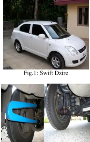
The spring is designed and fabricated by the company for rear suspension of sedan Swift Dzire replacing helical coil spring.
Fig.1: Swift Dzire
Fig 2 : Location of Coil Spring and composite spring at rear suspension
Fig.3.Composite C Spring
Geometry of composite C-Spring
Specification of Flat Composite C Spring
Parameters Value
Total Length of the spring L 530mm Distance between two flanges of spring 180mm
IJEDR1501041
International Journal of Engineering Development and Research (www.ijedr.org)219
Max Load given on spring 500kg
Weight of the leaf spring 4.5 Kg
Material Selection
A composite material is defined as a material composed of two or more constituents combined on a macroscopic scale by mechanical and chemical bonds. Composites are combinations of two materials in which one of the material is called the “matrix phase” is in the form of fibers, sheets, or particles and is embedded in the other material called the “reinforcing phase”. Many composite materials offer a combination of strength and modulus that are either comparable to or better than any traditional metallic metals. High damping capacity of composite materials can be beneficial in many automotive applications in which noise, vibration, and hardness is a critical issue for passenger comfort.In the present work the E-glass/epoxy is selected as the spring material. In E-glass/Epoxy, the E-glass is fiber material whereas Epoxy is thermoset matrix materials. An epoxy is a polymer that contains an epoxide group (one oxygen and two carbon atoms) in its chemical structure.
IV.FEA OF COMPOSITE C-SPRING UNDER STATIC LOAD
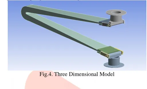
Three Dimensional Model
A three dimensional model of composite C-spring was made using Solid works.
Fig.4. Three Dimensional Model
Material Properties
The material useds for manufacturing Composite C- Spring is E-Glass Epoxy possessing following properties:
Table 1: Material Properties of Composite C-Spring
Density 1.49E-09 T/mm3
Ex 121000 MPa
Ey 8600 MPa
Ez 8600 MPa
µxy 0.27
µyz 0.4
µzx 0.27
Gxy 4700 MPa
Gyz 3100 MPa
Gxz 4700 MPa
Syt X 2231 MPa
The spring needs some fixture arrangement made up of steel material which has following properties considered for analysis.
Table 2: Material Properties of Spring seats
Density 7.85E-09 T/mm^3
E 2.00E+05 MPa
µ 0.3
FEA Element Types
1. Solid Element : SOLID187 element is a higher order 3-D, 10-node element. SOLID187 has a quadratic displacement behavior and is well suited to modeling irregular meshes.
IJEDR1501041
International Journal of Engineering Development and Research (www.ijedr.org)220
Fig.5. Bonded ContactFig.6. Mapped and Free Meshing
Boundary Conditions
The spring is constrained at the shown positions in the figure below. At point A, bottom spring seat, is fixed and the load is applied at top spring seat point B.
Fig.7. Boundary Constraints
IJEDR1501041
International Journal of Engineering Development and Research (www.ijedr.org)221
Fig.8 Directional Deformation for load 250kgFig.9 Principal Stress for load 250Kg
IJEDR1501041
International Journal of Engineering Development and Research (www.ijedr.org)222
Table 3. Result Table for Finite Element Stress AnalysisLoad Load Deflection Von-Mises Eq. Stress Principal Stress
Kg N mm Mpa Mpa
250 2452.5 57.26 592.31 484.67
300 2943 68.72 892.77 676.21
335 3286.35 76.73 996.92 755.1
350 3433.5 80.17 1041.6 788.91
Graph 4.1: Load Vs Deflection
V.HARMONIC RESPONSE ANALYSIS
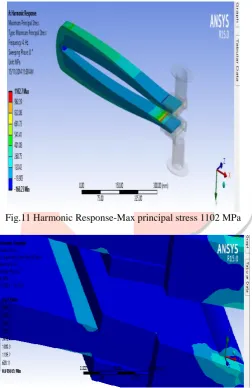
Harmonic response analysis is a technique used to determine the steady-state response of a linear structure to loads that vary sinusoidally (harmonically) with time. A quarter car model load of the vehicle approximately 250 Kg is applied on the spring and deflection is measured which is 57 mm. Over this deflection a bump of 70 mm is superimposed with the frequency of 4 Hz at its time period is 0.25 seconds. And dynamic stresses are observed as within the limit. Maximum Principal Stress in harmonic response obtained is 1102 MPa and equivalent Von-Mises stress is 1206 MPa.
Fig.11 Harmonic Response-Max principal stress 1102 MPa
Fig.12: Harmonic Response-Von Misces stress 1206 MPa
Modal Analysis using FEM
IJEDR1501041
International Journal of Engineering Development and Research (www.ijedr.org)223
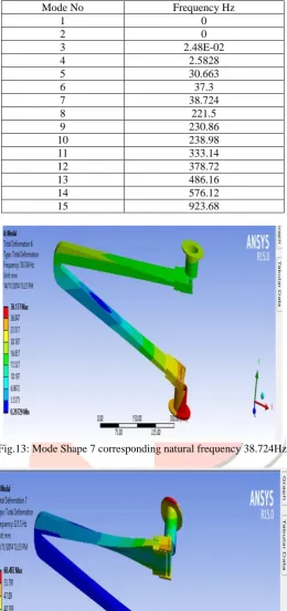
Table 4.5: Result of Modal Analysis using FEMMode No Frequency Hz
1 0
2 0
3 2.48E-02
4 2.5828
5 30.663
6 37.3
7 38.724
8 221.5
9 230.86
10 238.98
11 333.14
12 378.72
13 486.16
14 576.12
15 923.68
Fig.13: Mode Shape 7 corresponding natural frequency 38.724Hz
Fig.14: Mode Shape 8 corresponding natural frequency 221.5Hz
VI.CONCLUSION
IJEDR1501041
International Journal of Engineering Development and Research (www.ijedr.org)224
behavior of C-spring. Thus, it is good elastic material. The C-spring is having high stiffness and high strength to weight ratio. Apart from above conclusions, following advantages of composite C-spring are note worthy: Specially made to give effects like Air Suspension without any extra external energy.
No Permanent Deformation Hence No Re-tensioning. Thus No Maintenance.
Minimum Wear & Tear of Body parts and tyre. Due to delicate tendency of absorbing road shocks, Jerks & vibrations.
Softer ride, Lower Noise level, due to better damping characteristics.
Excellent Corrosion Resistance against atmospheric Pollutions.
Better life with consistency in performance around 1 million Fatigue Life Cycle. i.e. Minimum Five times better than metal leaf Spring.
Fully inter – changeable with conventional spring without any modification.
Increase in Fuel Efficiency due to better Aerodynamic. It cuts the wind with low coefficient of friction.
VII.ACKNOWLEDGEMENT
We are thankful to Dr. Nano Inc., Composite C-Spring Manufacturer, Ichalkaranji, Maharahtra, India, for providing us spring and details.
REFERENCES
[1] Mahmood M. Shokrieh , Davood Rezaei “Analysis and Optimization of a Composite Leaf Spring.” Composite Structures 60 (2003) pp 317–325.
[2] Senthil kumar and Vijayarangan, “Analytical and Experimental studies on Fatigue life Prediction of steel leaf spring and composite leaf multi leaf spring for Light Passenger vehicles Using Life Data Analysis” Material science Vol. 13 No.2 2007.
[3] B. Vijaya Lakshmi, Satyanaryana, “Static and Dynamic Analysis of Composite Leaf Spring Heavy Vehicle”, International Journal of Advanced Engineering Research and Studies, Vol.2,Oct-Dec.2012/pp80-84.
[4] T.Rangaswamy, S. Vijayarangan “Optimal Design And Analysis Of Automotive Composite Drive Shaft” International Symposium of Research Students on Materials Science and Engineering December 2002-04 pp 1-9.
[5] D. Abdul Budan, T. S. Manjunathan, “Investigation on the feasibility of composite coil spring for automotive applications”, World Academy of Science, Engineering & Technology, 46,2010
[6] V. Pozilarasu, T Parameshwaran Pillai, “Performance Analysis of Steel Leaf Spring with Composite Leaf Spring and Fabrication of Composite Leaf Spring”, International Journal of Engineering Research and Science and Technology Vol. 2, No.3, Aug 2013
[7] Zhang Jing, Wang Xiao-dong, Li Quan-bu, Jiang Ying, “Mechanical Properties of Short Carbon/Glass Fiber Reinforced High Mechanical Performance Epoxy Resins”, Journal of Chongqing University, English Edition,2009,8(4), 222-230 [8] M. Raghvendra, Syed Altaf Hussain, “Modelling and Analysis of Laminated Composite Leaf Spring under the Static
Load condition by using FEA,” Internationl Journal of Modern Engineering Research, Vol.2.,July-Aug.2012 pp1875-1879.
[9] Krishan K. Chawala, Composite Materials Science [10] & Engineering, Third Edition, Springer Publication
[11] Gokhale N. S., Deshpande S. S., Bedekar S. V. and Thite A. N., Practical Finite Element Analysis , Finite to Infinite, Pune.
[12] Carl T. Herakovich, “Mechanics of Fibrous Composites”, University of Virginia John Wiley & Sons, Inc. [13] A. M. Wahl ,“Mechanical Springs”, Spring Manufacturers Institute.