Improved Active Power Filter for Renewable
Power Generation Systems
Dr. K.Vinay kumar
Assistant Professor SVS Institute of Technology
Abstract- The performance analysis of four-leg voltage-source inverter using a Fuzzy logic control scheme is presented. The use of a four-leg voltage-source inverter allows the reduction of current harmonic components, as well as unbalanced and Negative sequence currents generated by single-phase nonlinear loads. The compensation performance of the proposed active power filter and the associated control scheme under steady state and transient operating conditions is demonstrated through simulations results.In recent times, fuzzy logic controller was applied for active power filter (APF) control application, as the APF is nothing but a current controlled VSI. In this paper, a fuzzy logic based shunt APF is presented based on the effective time concept. The effective time concept eliminates the trigonometric calculations and sector identification, thereby it reduces the computational effort. Simulation results demonstrate the efficacy of the APF with the fuzzy logic based control strategy. Simulation results are obtained for both PI controller and fuzzy logic controller and the results are compared. In the fuzzy controlled four leg inverter APF is used for power quality improvement.
Keywords: Fuzzy Logic Controller, Active power filter, current control, four-leg converters, predictive control Harmonics, and Power Quality.
I.INTRODUCTION
Renewable generation affects power quality due to its Increasing global energy consumption and noticeable environmental pollution are making renewable energy more important. Today, a small percentage of total global energy comes from renewable sources, mainly hydro and wind power. As more countries try to reduce greenhouse gas (GHG) emissions, new power generation capacity can no longer be met by traditional methods such as burning coal, oil, natural gas, etc. However, these DG units produce a wide range of voltages [1-5] due to the fluctuation of energy resources and impose stringent requirements for the inverter topologies and controls. To have sustainable growth and social progress, it is necessary to meet the energy need by utilizing the renewable energy resources like wind, biomass, hydro, co-generation, etc. In sustainable energy system, energy conservation and the use of renewable source are the key paradigm. The need to integrate the renewable energy like wind energy/PV into power system is to make it possible to minimize the environmental impact on conventional plant [6].
The integration of wind energy into existing power system presents technical challenges and that requires consideration of voltage regulation, stability, power quality problems. The power quality is an essential customer-focused measure and is greatly affected by the operation of a distribution and transmission network. The issue of
power quality is of great importance to the wind turbine [7-11].
This new scenario in power distribution systems will require more sophisticated compensation techniques. Although active power filters implemented with three-phase four-leg voltage-source inverters (4L-VSI) have already been presented in technical literature. The primary contribution of this paper is Fuzzy logic controller designed and implemented specifically for this application. Traditionally, active power filters have been controlled using a predictive control technique, such as fuzzy logic or adaptive, for the current as well as for the dc-voltage loops. Fuzzy controllers use the non-linear model, which is closer to real operating conditions compare to predictive control. An accurate model obtained using fuzzy controller improves the performance of the active power filter, especially during transient operating conditions, because it can quickly follow the current-reference signal while maintaining a constant dc voltage [12-15].
The mathematical model of the 4L-VSI and the principles of operation of the proposed predictive control scheme, including the design procedure. The complete description of the selected current reference generator implemented in the active power filter is also presented [16].
II. FOUR-LEG CONVERTER MODEL It consists of various types of power generation units and different types of loads. Renewable sources, such as wind and sunlight, are typically used to generate electricity for residential users and small industries. Both types of power generation use ac/ac and dc/ac static PWM converters for voltage conversion and battery banks for long term energy storage. These converters perform maximum power point tracking to extract the maximum energy possible from wind and sun. The electrical energy consumption behavior is random and unpredictable, and therefore, it may be single- or three-phase, balanced or unbalanced, and linear or nonlinear. An active power filter is connected in parallel at the point of common coupling to compensate current harmonics, current unbalance, and reactive power. It is composed by an electrolytic capacitor, a four-leg PWM converter, and a first-order output ripple filter, as shown in Fig. 1. This circuit considers the power system equivalent impedance Zs, the converter output ripple filter impedance Zf, and the load impedance ZL.
output voltage quality, and is suitable for current unbalanced compensation.
Fig.1.Three-Phase Equivalent Circuit of the Proposed Shunt Active Power Filter.
Fig.2. Two-level four-leg PWM-VSI topology
The voltage in any leg x of the converter, measured from the neutral point (n), can be expressed in terms of switching states, as follows:
(1)
The mathematical model of the filter derived from the equivalent circuit shown in Fig. 1 is
(2)
Where Req and Leq are the 4L-VSI output parameters expressed as Thevenin’s impedances at the converter output terminals Zeq. Therefore, the Thevenin’s equivalent impedance is determined by a series connection of the ripple filter impedance Zf and a parallel arrangement between the system equivalent impedance Zs and the load impedance ZL.
(3) For this model, it is assumed that ZL _ Zs, that the resistive part of the system’s equivalent impedance is neglected, and that the series reactance is in the range of 3–7% p.u., which is an acceptable approximation of the real system. Finally,
Req = Rf and Leq = Ls + Lf (4) III. REFERENCE CURRENT GENERATION
SCHEME
A dq-based current reference generator scheme is used to obtain the active power filter current reference signals.
This scheme presents a fast and accurate signal tracking capability. This characteristic avoids voltage fluctuations that deteriorate the current reference signal affecting compensation performance. The current reference signals are obtained from the corresponding load currents as shown in Fig. 4. This module calculates the reference signal currents required by the converter to compensate reactive power, current harmonic and current imbalance. The displacement power factor (sin φ(L) ) and the maximum total harmonic distortion of the load (THD(L) ) defines the relationships between the apparent power required by the active power filter, with respect to the load, as shown
(5)
Where the value of THD (L) includes the maximum compensable harmonic current, defined as double the sampling frequency fs. The frequency of the maximum current harmonic component that can be compensated is equal to one half of the converter switching frequency. The dq-based scheme operates in a rotating reference frame; therefore, the measured currents must be multiplied by the sin (wt) and cos(wt) signals. By using dq-transformation, the d current component is synchronized with the corresponding phase-to-neutral system voltage, and the q current component is phase-shifted by 90◦. The sin(wt) and cos(wt) synchronized reference signals are obtained from a synchronous reference frame (SRF) PLL. The SRF-PLL generates a pure sinusoidal waveform even when the system voltage is severely distorted. Tracking errors are eliminated, since SRF-PLLs are designed to avoid phase voltage unbalancing, harmonics (i.e., less than 5% and 3% in fifth and seventh, respectively), and offset caused by the nonlinear load conditions and measurement errors [3], the relationship between the real currents iLx(t) (x = u, v,w) and the associated dq components (id and iq).
Fig.3. Dq-Based Current Reference Generator Block Diagram.
converter reference current must be modified by adding an active power reference signal ie with the d-component. The resulting signals i*d and i*q are transformed back to a three-phase system by applying the inverse Park and Clark transformation, The cut off frequency of the LPF used in this paper is 20 Hz.
(7) The current that flows through the neutral of the load is compensated by injecting the same instantaneous value obtained from the phase-currents, phase-shifted by 180◦, as shown next.
(8) One of the major advantages of the dq-based current reference generator scheme is that it allows the implementation of a linear controller in the dc-voltage control loop. However, one important disadvantage of the dq-based current reference frame algorithm used to generate the current reference is that a second order harmonic component is generated in id and iq under unbalanced operating conditions. The amplitude of this harmonic depends on the percent of unbalanced load current (expressed as the relationship between the negative sequence current iL,2 and the positive sequence current iL,1 ). The second-order harmonic cannot be removed from id and iq , and therefore generates a third harmonic in the reference current when it is converted back to abc frame. Since the load current does not have a third harmonic, the one generated by the active power filter flows to the power system.
A.DC Link Voltage Control
The dc-voltage converter is controlled with a traditional PI controller. This is an important issue in the evaluation, since the cost function is designed using only current references, in order to avoid the use of weighting factors. Generally, these weighting factors are obtained experimentally, and they are not well defined when different operating conditions are required. Additionally, the slow dynamic response of the voltage across the electrolytic capacitor does not affect the current transient response. For this reason, the PI controller represents a simple and effective alternative for the dc-voltage control. The dc-voltage remains constant (with a minimum value of sqrt of 6vs (rms) until the active power absorbed by the converter decreases to a level where it is unable to compensate for its losses. The active power absorbed by the converter is controlled by adjusting the amplitude of
the active power reference signal ie, which is in phase with each phase voltage. In the block diagram shown in Fig. 4, the dc-voltage vdc is measured and then compared with a constant reference value v*dc. The error (e) is processed by a PI controller, with two gains, Kp and Ti. Both gains are calculated according to the dynamic response requirement. Fig. 4 shows that the output of the PI controller is fed to the dc-voltage transfer function Gs which is represented by a first-order system.
Fig.4. DC-voltage control block diagram.
(9) The equivalent closed-loop transfer function of the given system with a PI controller
(10)
Since the time response of the dc-voltage control loop does not need to be fast, a damping factor ζ = 1and a natural angular speed ωn = 2π · 100 rad/s are used to obtain a critically damped response with minimal voltage oscillation. The corresponding integral time Ti = 1/a (13) and proportional gain Kp can be calculated as
(11) IV.FUZZY LOGIC CONTROL
desirable both small signal and large signal dynamic performance at same time, which is not possible with linear control technique. Thus, fuzzy logic controller has been potential ability to improve the robustness of compensator.
The basic scheme of a fuzzy logic controller is shown in Fig 5 and consists of four principal components such as: a fuzzy fication interface, which converts input data into suitable linguistic values; a knowledge base, which consists of a data base with the necessary linguistic definitions and the control rule set; a decision-making logic which, simulating a human decision process, infer the fuzzy control action from the knowledge of the control rules and linguistic variable definitions; a de-fuzzification interface which yields non fuzzy control action from an inferred fuzzy control action [10].
Fig.5. Block diagram of the Fuzzy Logic Controller (FLC) for proposed converter.
Fig.6. Membership functions for error.
Fig.7. Membership functions for change_in_error.
Fig.8. Membership functions for Output.
Table II
Table rules for error and change of error.
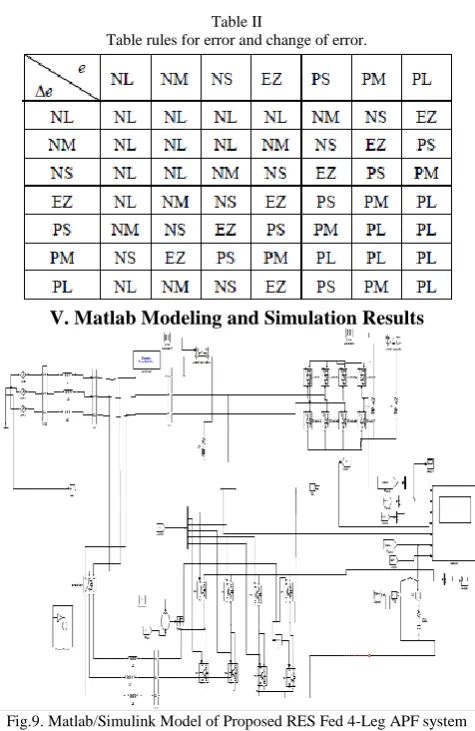
V. Matlab Modeling and Simulation Results
Fig.9. Matlab/Simulink Model of Proposed RES Fed 4-Leg APF system with formal PI & Intelligence Controllers.
Fig.10. Simulation results for APF with Formal PI Controller (a) Source Voltage. (b) Load current. (c) Compensator Current.
(d) Neutral Current, (e) Source Current (f) DC Link Voltage.
Fig.10. Simulation results for APF with Formal PI Controller (a) Source Voltage. (b) Load current. (c) Compensator Current, (d) Neutral Current, (e) Source Current (f) DC Link Voltage. Here compensator is turned on at 0.05 seconds, before we get some harmonics coming from non-linear load, then distorts our parameters and get sinusoidal when compensator is in on.
Fig.11. Power Factor for APF with Conventional PI Controller.
Fig.11. shows the power factor it is clear from the figure after compensation power factor is unity.
Fig.12. FFT Analysis of Phase-A Source Current with PI Controlled APF
Fig.12. shows the FFT Analysis of Phase-A Source Current with PI Controlled APF, here we get 2.41%. Case 2: Proposed APF with Intelligence based Fuzzy Controller
Fig.13. Simulation results for APF with Fuzzy Controller (a) Source Voltage. (b) Load current. (c) Compensator Current.
(d) Neutral Current, (e) Source Current (f) DC Link Voltage.
linear load, then distorts our parameters and get sinusoidal when compensator is in on.
Fig.14. Power Factor for APF with Fuzzy Controller
Fig.14.shows the power factor it is clear from the figure after compensation power factor is unity.
Fig.15. FFT Analysis of Phase-A Source Current with Fuzzy Controlled APF.
Fig.15. shows the FFT Analysis of Phase-A Source Current with Fuzzy Controlled APF, here we get 0.95%.
VI. CONCLUSION
The harmonics caused by nonlinear loads result in low power factor and losses in power systems. To minimize this problem, shunt active power filters have been used. A fuzzy controlled shunt active filter is presented in the paper. The use of a Fuzzy logic controller proved to be an effective solution for active power filter applications, improving current tracking capability, and transient response. Simulated results have proved that the proposed Fuzzy control method is a good alternative to classical linear control methods. Simulated results have shown the compensation effectiveness of the proposed active power filter. By using conventional controller we get THD value
is 2.41%, but using the fuzzy logic controller THD value is 0.95%. Simulated results have proved that the proposed predictive control algorithm is a good alternative to classical linear control methods.
REFERENCES
[1] J. Rocabert, A. Luna, F. Blaabjerg, and P. Rodriguez, “Control of power converters in AC micro grids,” IEEE Trans. Power Electron., vol. 27, no. 11, pp. 4734–4749, Nov. 2012.
[2] M. Aredes, J. Hafner, and K. Heumann, “Three-phase four-wire shunt active filter control strategies,” IEEE Trans. Power Electron., vol. 12, no. 2, pp. 311–318, Mar. 1997.
[3] S. Naidu and D. Fernandes, “Dynamic voltage restorer based on a four leg voltage source converter,” Gener. Transm. Distrib., IET, vol. 3, no. 5, pp. 437–447, May 2009.
[4] N. Prabhakar and M. Mishra, “Dynamic hysteresis current control to minimize switching for three-phase four-leg VSI topology to compensate nonlinear load,” IEEE Trans. Power Electron., vol. 25, no. 8, pp. 1935– 1942, Aug. 2010.
[5] G.Satyanarayana., K.N.V Prasad, G.Ranjith Kumar, K. Lakshmi Ganesh, "Improvement of power quality by using hybrid fuzzy controlled based IPQC at various load conditions," Energy Efficient Technologies for Sustainability (ICEETS), 2013 International Conference on , vol., no., pp.1243,1250, 10-12 April 2013..
[6] F. Wang, J. Duarte, and M. Hendrix, “Grid-interfacing converter systems with enhanced voltage quality for micro grid application; concept and implementation,” IEEE Trans. Power Electron., vol. 26, no. 12, pp. 3501– 3513, Dec. 2011.
[7] X.Wei, “Study on digital pi control of current loop in active power filter,” in Proc. 2010 Int. Conf. Electr. Control Eng., Jun. 2010, pp. 4287– 4290.
[8] R. de Araujo Ribeiro, C. de Azevedo, and R. de Sousa, “A robust adaptive control strategy of active power filters for power-factor correction, harmonic compensation, and balancing of nonlinear loads,” IEEE Trans. Power Electron., vol. 27, no. 2, pp. 718–730, Feb. 2012. [9] J. Rodriguez, J. Pontt, C. Silva, P. Correa, P. Lezana, P. Cortes, and U. Ammann, “Predictive current control of a voltage source inverter,” IEEE Trans. Ind. Electron., vol. 54, no. 1, pp. 495–503, Feb. 2007. [10] Satyanarayana, G.; Ganesh, K.Lakshmi; Kumar, Ch. Narendra; Krishna, M.Vijaya, "A critical evaluation of power quality features using Hybrid Multi-Filter Conditioner topology," Green Computing, Communication and Conservation of Energy (ICGCE), 2013 International Conference on , vol., no., pp.731,736, 12-14 Dec. 2013. [11] R. Vargas, P. Cortes, U. Ammann, J. Rodriguez, and J. Pontt, “Predictive control of a three-phase neutral-point-clamped inverter,” IEEE Trans. Ind. Electron., vol. 54, no. 5, pp. 2697–2705, Oct. 2007. [12] P. Cortes, A. Wilson, S. Kouro, J. Rodriguez, and H. Abu-Rub, “Model predictive control of multilevel cascaded H-bridge inverters,” IEEE Trans. Ind. Electron., vol. 57, no. 8, pp. 2691–2699, Aug. 2010. [13] P. Lezana, R. Aguilera, and D. Quevedo, “Model predictive control of an asymmetric flying capacitor converter,” IEEE Trans. Ind. Electron., vol. 56, no. 6, pp. 1839–1846, Jun. 2009.
[14] P. Correa, J. Rodriguez, I. Lizama, and D. Andler, “A predictive control scheme for current-source rectifiers,” IEEE Trans. Ind. Electron., vol. 56, no. 5, pp. 1813–1815, May 2009.