Spatial Structure of Electromagnetic Field Diffracted
by a Sub-Wavelength Slot in a Thick Conducting Screen
Vladimir M. Serdyuk1, *, Joseph A. Titovitsky1, Svetlana V. von Gratowski2, and Victor V. Koledov2
Abstract—The eigen-mode technique of rigorous diffraction theory is employed for computation of spatial structure of electromagnetic field, arising under diffraction of a plane wave by a narrow slot of the width of the order of the wavelength or smaller in a perfectly conducting screen of finite thickness. The effects of little step change and of strong enhancement for relative averaged energy density are investigated in dependence of the slot width and depth. It is shown that the field in a space behind the slot represents the sum of a field, slowly and monotonically decreasing in the directions away from a slot, and a harmonic field with sinusoidal spatial inhomogeneities of the order of the wavelength. It is established that the comparative contributions of these two field constituents are unequal for various spatial components of the electric and magnetic fields, and also that the contribution of the first constituent decreases with increase of the slot width.
1. INTRODUCTION
Not so long ago, the authors of the work [1] have paid attention to the interesting effect of anomalous high concentration of electromagnetic energy under its transmission through narrow sub-wavelength holes in metallic screens. The subsequent investigations [2–5] have confirmed that such apertures and gaps in metal surfaces can tightly localize electromagnetic waves well below the diffraction limit and lead to strong field enhancements. These effects have been observed as for solitary apertures [2], as for their quasi-ordered or well-ordered set, forming a regular two-dimensional grating on a conducting surface [3, 4]. Great interest in such effects is generated by the opportunity of local field action on solitary nanoparticles and their applications to terahertz spectroscopy of separated molecules [4].
The standard approximate theory of optical transmission through apertures [6] is not applicable to modeling of the observed phenomenon, because the aperture dimension is of the order of the wavelength or smaller. Here, one should utilize the exact theory. For that, numerical methods (for example, the finite element method [3]) and various analytical and semi-analytical methods were used (see the review [5]). With the help of those one succeeded in explaining of basic anomalous effects of narrow slots transmission. However, in most cases, researchers restrict their consideration to theoretical computation of energetic parameters on the slot output immediately, and they have paid little attention to study of the field structure in the space behind that. In the present work, the main features of spatial structure of the narrow slot diffraction field are investigated in all regions of its propagation inside the slot and behind the screen. Our consideration uses a rigorous theoretical model of plane wave diffraction by a slot in a perfectly conducting screen of finite thickness [7], based on the eigen-mode technique.
Received 16 February 2018, Accepted 30 April 2018, Scheduled 26 May 2018
* Corresponding author: Vladimir M. Serdyuk ([email protected]).
1 Institute of Applied Physical Problems, Belarusian State University, Minsk, Belarus. 2Kotel’nikov Institute of Radioengineering
2. BASIC THEORY AND RESULTS OF COMPUTATIONS
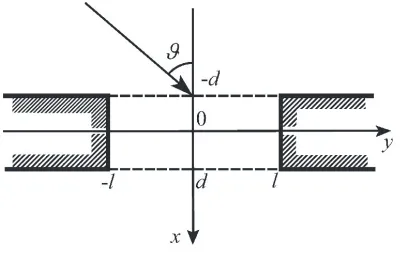
We consider the problem of the stationary plane wave diffraction by a narrow slot in a thick perfectly conducting screen of finite thickness (Fig. 1), whose exact solution is presented in [7]. Here, the 2D diffraction picture is studied for two polarizations of incident wave, H (or TE) and E (or TM). The fields of the H polarization in all regions have the electric vector orthogonal to the plane of incidence xy (Fig. 1), being determined by the following equations (in the Gaussian system of units) [6, 8]
Ez =u Hx =−
i k
∂u
∂y Hy = i k
∂u
∂x (1a)
and for theE polarization the magnetic vector of fields is orthogonal to this plane
Ex=
i k
∂u
∂y Ey =− i k
∂u
∂x Hz =u (1b)
where u is the scalar field function, which should satisfy the Helmholtz equation [6], i the imaginary unite,k= 2π/λthe wavenumber, andλthe wavelength of radiation (the exponential factor exp(−iωt), determining the temporal dependence of all fields, is omitted everywhere). The solutions for these polarizations separately proceed from representation of fields in various regions as superposition of their eigenmodes in they-coordinate, satisfying the Maxwell equations and, partially, appropriate boundary conditions.
Figure 1. Geometry of the problem.
For example, inside the slot, the scalar field function is presented in the form of infinite sum of discrete modes, because their field function (for the H polarization) or its normal derivative (for theE polarization) should vanish on the slot walls (aty=±l)
u = +∞ ∑
n=1 {
σ(−sν)n [
a(ns)exp(ikσ(s)n(d+x)
)
+ (−1)νb(ns)exp(ikσ(s)n(d−x)
)]
cos(kξ(s)ny
)
+iσ−(aν)n [
an(a)exp(ikσ(a)n(d+x))+ (−1)νbn(a)exp(ikσ(a)n(d−x))]sin(kξ(a)ny) } (2)
whereν = 0,
ξ(s)n= (π/kl)(n−1/2) ξ(a)n= (π/kl)n (3a)
for theH polarization, andν = 1,
ξ(s)n= (π/kl)(n−1) ξ(a)n= (π/kl)(n−1/2) (3b) for theE polarization, being
σ(s,a)n=
√ 1−ξ2
(s,a)n (4)
opposite directions along the slot depth (in thex coordinate), but in the direction of the y coordinate, the field of each of these modes is a standing wave, being symmetrical (index (s)) or antisymmetrical (index (a)) in this coordinate.
In contrast to [7], here we use dimensionless values of parameters of propagationξ(s,a)n and σ(s,a)n for all modes, extracting the dimensional multiplierkfrom these parameters.
Because of the absence of any constraints in the y-direction outside the slot, the spectrum of eigenmodes is continuous and is represented by the Fourier integral. For example, in the region behind the screen (x≥d), which represents a free half-space,
u= ∫ +∞
−∞ α
−νB(β) exp{ik[α(x−d) +βy]}dβ (5)
where
α=√1−β2 (6)
B(β) are the amplitudes of the continuous spectrum modes, being dependent on the propagation constantβ. Determining the parameter of normal propagationαas Eq. (6) with nonnegative imaginary part, we provide satisfaction of the Helmholtz equation for the diffraction field in Eq. (5) and its decrease at great distances from a slot. In the region before the screen (x ≤ −d) one should take into consideration the field of an incident plane wave with the unit amplitude
u = {exp[ikα0(x+d)]−(−1)νexp[−ikα0(x+d)]}exp(ikβy)
+(−1)ν ∫ +∞
−∞ α
−νA(β) exp{ik[−α(x+d) +βy]}dβ (7)
where α0 = cosϑ, β0 = sinϑ, ϑ is the angle of incidence of a diffracting wave on the surface of a screen, showing angular deflection of its direction of propagation from the normal to this surface. Here, we extract a reflected wave (the second summand in the figured brackets) also in the explicit form. Amplitudes of all diffraction modes in various regions a(ns,a), bn(s,a), A(β) and B(β) are initially
unknown, and they are determined in the process of diffraction problem solving from the boundary conditions on the planesx=−dand x= +d, coinciding with the boundaries of a screen [7].
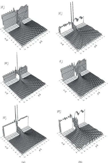
After determining of modes amplitudes in all regions with the help of Equations (2), (5) or (7), one can compute the spatial components of the electric and magnetic fields in every point of space, substituting these equations into Eq. (1) [7]. Figs. 2 and 3 show the results of such computation for the fields of theH andE polarizations in the same scale for two specific cases, which give a general insight about structure of field of diffraction by the slot in a thick screen. These results are computed for the case, when the angle of incidence ϑ = 30◦. For the case of normal incidence, when ϑ = 0◦, spatial structure of fields is analogous to the first one, but it becomes purely symmetrical or antisymmetrical in they coordinate.
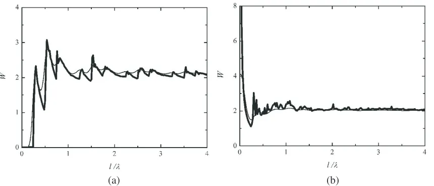
Using the spatial field components, one can determine local distribution of its energetic parameters, more particularly, calculate the averaged output density of electric field W for a slot (at x = +d, −l≤y≤l), which is proportional to the integral of squared absolute value of electric vector in the slot width.
W = (2l)−1 ∫ +l
−l
|Ez(d, y)|2dy or W = (2l)−1
∫ +l
−l
(
|Ex(d, y)|2+|Ey(d, y)|2
) dy
(a) (b)
(a) (b)
(a) (b)
Figure 4. Relative averaged energy densityW on the exit of a slot aperture as a function of its half-width l at two different values of the screen half-thickness (slot half-depth) d= 0.1λ (thin lines) and d= 3.0λ (thick lines) for (a) the H polarization and for (b) the E polarization of incident wave; the angle of incidenceϑ= 30◦.
the slot width provides slow decrease of the tangential propagation parameters ξ(s,a)n for slot modes and connection of a regular mode to the process of effective energy transmission through a slot, as its normal propagation parameterσ(s,a)n(4) becomes real. Such connection displays as a sharp increase of transmitted energy. However after that for some time, the number of modes, being effective transmitters, remains unchanged, and the energy density decreases with increase of the slot width. The described effect appears more explicitly in the cases of thick screens, where the presence of decay in slot modes provides small value of their fields on the slot output, and at the same time for slots of small depth, decaying modes can make appreciable contribution here to the total field.
For the E polarization (Fig. 4(b)), this effect is concealed by the other phenomenon — singular behavior of the fields at the edges of a slot. It is known that spatial components of electric field, which is normal to the edges, increase in magnitude with decrease of distance from those as an inverse cube root of this distance [9]. The spatial region of this anomaly near edges is very small, so for a wide slot its influence on the energy density is not substantial. However for a narrow slot, the anomalous region can cover its width wholly, causing here very great magnitude of energy density. Fig. 4 demonstrates that at l <0.1λ the averaged energy density of transmitted field on a slot is 4 and greater than that of the incident wave in free space by the factor of 4 and more. This effect provides the opportunity for devices with narrow sub-wavelength slots to stand duty as local concentrators of electromagnetic energy and to play the part of nanoantennae.
The dependences look like those observed under change of the wavelength of transmitting radiation with unchanged slot width [5], since here the absolute value of the slot width 2l does not matter, but its relative value in comparison with the wavelength 2l/λ is of importance. However, the appearance of curves for both cases is distinguished one from the other because the wavelength change causes the change of the relative slot depth 2d/λ(the screen thickness).
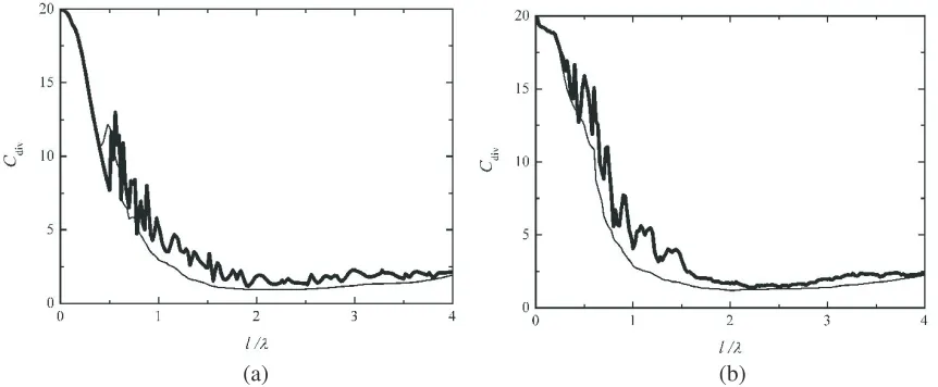
Considering the field in space behind the narrow slot, one should take into account its great divergence at subsequent propagation in free space (at x > d) (see Figs. 2 and 3), which is caused by scattering on the edges [7, 10]. Such divergence can be evaluated by a scalar parameter Cdiv [10],
(a) (b)
Figure 5. Integral divergence of diffraction field Cdiv on the distance of 4.0λfrom a slot as a function
of its half-width l at two values of the screen half-thickness (slot half-depth) d= 0.1λ (thin lines) and d= 3.0λ(thick curves) for (a) the H polarization and for (b) the E polarization of field; the angle of incidence ϑ= 30◦.
effect is the presence of the minimum of divergence in the region where the slot half-width l ≈2.0λ, when the effective image width is about twice the slot width. At subsequent increase of the half-width l, divergence demonstrates slow rise, although it would seem that increase of a transmitting aperture should cause only decrease of transverse diffraction divergence.
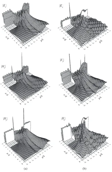
It should be borne in mind that diffraction convergence as a scalar parameter is a space-averaged characteristic of transmitting field and leaves out of account many features of its spatial structure. Figs. 2 and 3 display such a structure for two cases of various slot half-widthl= 0.375λandl= 2.0λ, when the diffraction divergence is Cdiv = 8.63 and Cdiv = 1.72, respectively. Obviously, in the second case, the
field accumulates greater in the region of geometrooptical image at−l+(x−d) tanϑ < y < l+(x−d) tanϑ (ϑis the angle of incidence), but for a wide slot as for a narrow one, the lateral amplitude distribution in the plane y= const is characterized by the presence of spatial inhomogeneities of various scales.
It is known that the emission of a narrow aperture in the far zone is similar to the emission of a point source, and the smaller the aperture width is, the closer is the picture of its emission to the picture of divergent spherical waves. However, Figs. 2 and 3 show that the spatial field distribution in the near zone bears little resemblance to the picture of a spherical wave. One can notice that for a narrow slot (Fig. 2) the field behind that is represented by superposition of two fields: the first is a field which characterized by great-scale inhomogeneities and decreases monotonically in all directions away from the slot, and the second one is a harmonic field, which changes in space periodically in the sinusoidal fashion with the period of the order of the wavelength. For the tangential field components Ez, Hy
(theH polarization) andEy (theE polarization), which are parallel to the screen boundaries, the first
constituent is dominant, but for the normal components Ex,Hx, and also for the tangential magnetic
component Hz, the contribution of this part is small, and a dominant constituent is harmonic one.
3. CONCLUSION
The rigorous electromagnetic diffraction theory provides the opportunity to explain energetic effects of electromagnetic radiation transmission through sub-wavelength slots of small width, such as the effect of its great concentration near slot edges, and also the effect of saw-toothed increase of averaged energy density on the slot output. They are caused by a specific spatial structure of diffraction fields in the slot and near its boundaries. However, together with increase of electromagnetic energy density on the slot output with decrease of its width, one obtains also increase of divergence of output radiation. In contradiction to slots with a wide aperture, where fast field decay occurs on the boundaries of a transmitting beam, a narrow slot determines very smooth decrease in the propagation direction and in the transverse direction, what is well illustrated by Figs. 2 and 3. About possible applications of narrow slot energetic effects for local-pointwise excitation of nanoparticles or molecules, such excitation can be realized only in the cases, when energy excitation has a threshold character and when the value of threshold energy density is exceeded by radiation intensity only in a small region near a slot output. The field behind the slot represents the superposition of the field with great-scale spatial inhomogeneities in amplitude and harmonic field, which changes in space in a sinusoidal fashion with the period of the order of the radiation wavelength. For various spatial field components, the comparative contributions of these two constituents are not equal: for the tangential electric components, which are parallel to a screen, and for the magnetic component, which is parallel to a screen and is normal to the slot edges, the first constituent is greater, but with increase of slot width the contribution of that into the total diffraction field decreases.
ACKNOWLEDGMENT
The authors would like to thank Russian Foundation for Basic Research for support of the work (grant No. 17-57-560002 Iran a).
REFERENCES
1. Ebbesen, T. W., H. J. Lezec, H. F. Ghaemi, T. Thio, and P. A. Wolff, “Extraordinary optical transmission through sub-wavelength hole arrays,” Nature, Vol. 391, No. 12, 667–669, 1998. 2. Chen, X., H.-R. Park, N. Lindquist, J. Shaver, M. Pelton, and S.-H. Oh, “Squeezing millimeter
waves through a single, nanometer-wide, centimeter-long slit,” Scientific Reports, Vol. 4, 6722, 2014.
3. Park, H.-R., X. Chen, N.-C. Nguyen, J. Peraire and S.-H. Oh, “Nanogap-enhanced terahertz sensing of 1 nm thick (λ/106) dielectric films,” ACS Photonics, Vol. 2, No. 3, 417–424, 2015.
4. Toma, A., S. Tuccio, M. Prato, F. De Donato, A. Perucchi, P. Di Pietro, S. Marras, C. Liberale, R. P. Zaccaria, F. De Angelis, L. Manna, S. Lupi, E. Di Fabrizio, and L. Razzari, “Squeezing terahertz light into nanovolumes: Nanoantenna enhanced terahertz spectroscopy (NETS) of semiconductor quantum dots,” Nano Lett., Vol. 15, No. 1, 386–391, 2015.
5. Garcia-Vidal, F. J., L. Martin-Moreno, T. W. Ebbesen, and L. Kuipers, “Light passing through subwavelength apertures,” Reviews of Modern Physics, Vol. 82, No. 1, 729–787, 2010.
6. Born, M. and E. Wolf,Principles of Optics, Cambridge University Press, Cambridge, 1997. 7. Serdyuk, V. M., “Diffraction of a plane electromagnetic wave by a slot in a conducting screen of
arbitrary thickness,” Technical Physics, Vol. 50, No. 8, 1076–1083, 2005. 8. Kong, J. A.,Electromagnetic Wave Theory, Wiley, New York, 1986.
9. Meixner, J., “The behavior of electromagnetic fields at edges,” IEEE Trans. Antennas and Propagat., Vol. 20, No. 4, 442–446, 1972.