A Compact Microstrip Triplexer with a Novel Structure Using Patch
and Spiral Cells for Wireless Communication Applications
Abbas Rezaei1, Salah I. Yahya2, 3, *, Saman Moradi4, and Mohd H. Jamaluddin5
Abstract—In this work, a novel planar four-port microstrip triplexer is designed and analyzed to operate at 1.9 GHz, 2.5 GHz, and 3.35 GHz for wireless communication applications. The proposed structure consists of a compact patch and spiral cells. The main advantage of this triplexer is its very compact size, with a cross size of only 15 mm × 15 mm (0.017λ2g). Sharp frequency response at the edges of all passbands, low insertion losses (0.25 dB, 0.4 dB and 0.11 dB), and high return losses (45 dB, 54 dB and 40 dB) in all channels are the other advantages of the designed triplexer. Additionally, the triplexer has reasonable isolations (S23,S24,S34), better than 20 dB. To verify the design method, both EM simulation and measurement results are obtained. The comparison shows that the measured and simulated results are in good agreement, which proves the feasibility of this work.
1. INTRODUCTION
Multi-channel microstrip devices such as multiplexers [1, 2] and multi-channel diplexers [3, 4] are strongly demanded by modern multi-channel communication systems. They have been utilised to select desired signals among crowded frequency bands. A type of multiplexer with three channels is called a triplexer. Recently, compact and high-performance microstrip triplexers are highly attractive for multi-channel wireless and mobile systems. Accordingly, several types of microstrip triplexers have been reported in [5–23]. Their designs are based on various types of microstrip resonators. In [5], step impedance and two different types of spiral resonators have been utilised to achieve a triplexer. A common triple-mode resonator in [6], coupled open loops and hairpins in [7], step impedance resonator, radial and coupled lines in [8], two coupled bumpy lines in [9], and coupled hairpins and spirals in [10] have been used to design microstrip triplexers. In [11, 12], based on asymmetric split-ring resonators, two microstrip triplexers have been designed. Using coupled hairpins, coupled U-shape and T-shape cells, a lowpass-bandpass triplexer with good isolation has been proposed in [13]. High impedance sections, and coupled open-loop resonator [14], parallel coupled lines integrated by a T-junction cell [15], and coupled hairpins [16] are the other utilised structures. The coupled hairpins and coupled open loops are commonly used in triplexer structures. Accordingly, they have little novelty in their structures. Moreover, coupled hairpins and open loops have been used in [17–19] as well. In [21], a wide stopband microstrip triplexer has been presented using uniform impedance resonators (UIR). It has an attenuation of−20 dB up to 8fo, wherefo is its first resonant frequency. In [22], a manifold microstrip triplexer has been introduced based on a new synthesis approach for multiplexing networks.
A triplexer occupies a large area, due to having several different ports and channels. Hence, all designed triplexers in [5–22] are very large, with the exception of [11]. In addition to minimisation,
Received 1 June 2019, Accepted 1 August 2019, Scheduled 14 August 2019
* Corresponding author: Salah I. Yahya ([email protected]).
another design purpose is improvements in the insertion and return losses. However, another common disadvantage of the proposed triplexers in [5–20] is their high insertion losses and low return losses in all channels.
In this paper, a novel miniaturised high-performance triplexer is designed. It has the most compact size, near the size of proposed triplexer in [11], the lowest insertion losses, and better return losses than the previous works. These advantages are obtained, along with proposing a novel structure. To design the introduced triplexer, a novel resonator consisting of integrated patches and spiral cells is proposed and theoretically analyzed.
The triplexer design is organized as follows: First, a compact resonator is selected. Second, anLC model of the resonator is presented and analyzed. Third, based on the proposed resonator, a compact triplexer is designed and fabricated.
2. TRIPLEXER STRUCTURE AND DESIGN
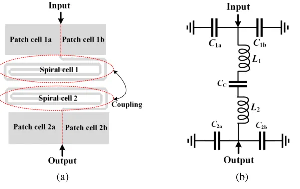
Coupled spirals connected to patch cells are a suitable structure to create a passband channel. The spiral cells have inductance features while they are compact. Therefore, they are attractive to be used in microstrip structures. When two spiral cells are coupled to each other, the coupling capacitors and spiral inductors can produce a good bandpass. To control the frequency response easily and get a higher degree of freedom, the patch cells can be added to coupled spirals, as presented in Fig. 1(a). Similar to spirals, the patch cells can save the size significantly, where they show capacitance properties. As depicted in Fig. 1(a), the proposed resonator includes two patch cells where each patch is divided into two cells presented as patch cells 1a, 1b, 2a, and 2b. An approximated LC circuit of the proposed resonator is presented in Fig. 1(b). In the LC model, patch cells 1a, 1b, 2a, and 2b are replaced by capacitors C1a, C1b, C2a, and C2b, respectively. Moreover, spiral cells 1 and 2 are presented by inductorsL1 andL2, respectively. As mentioned in [23], the effects of bents and steps are ignorable at the frequencies lower than 10 GHz. The coupling between spirals is shown with capacitor CC.
(a) (b)
Figure 1. Proposed resonator. (a) Layout. (b)LC model.
The input impedance of theLC circuit, viewed from the input port, when the output port is open, can be calculated as follows:
Zin= 1
jωC1
+ 1
jωC2
+ 1
jωCc + (L1+L2)jω= 1
jω
C1C2+CcC2+CcC1−ω2(L1+L2)C1C2Cc
C1C2Cc
(1)
where
In Eq. (1),ω is an angular frequency. Parameters C1 andC2 are the equivalent capacitors of patch cells that are connected to the input and output ports, respectively. A resonance frequency can be created when the impedance is a real parameter. Accordingly, an angular resonance frequency of ωo from Eq. (1) must be written as follows:
Zin = 0⇒C1C2+CcC2+CcC1−ω2o(L1+L2)C1C2Cc = 0⇒
ωo =
1
C1(L1+L2)
+ 1
Cc(L1+L2)
+ 1
C2(L1+L2)
(2)
As shown in Eq. (2), the patch cells with the equivalent capacitors C1 and C2 give us a higher degree of freedom to control the resonance frequency. By setting the parameters according to Eq. (2), we can set the resonance frequency at the desired point. Since the coupling capacitor is inherently a small capacitor, capacitors C1 and C2 should be large. Accordingly, the patch cells are selected due to compact size with large capacitance features. After choosing the desired dimensions of patch cells, we can select the dimensions of spiral cells based on a predetermined target resonance frequency. The dimensions of patches and spirals must be consistent with Eq. (2). The method for finding inductor and capacitor values according to the dimensions of the microstrip cell is explained in [24].
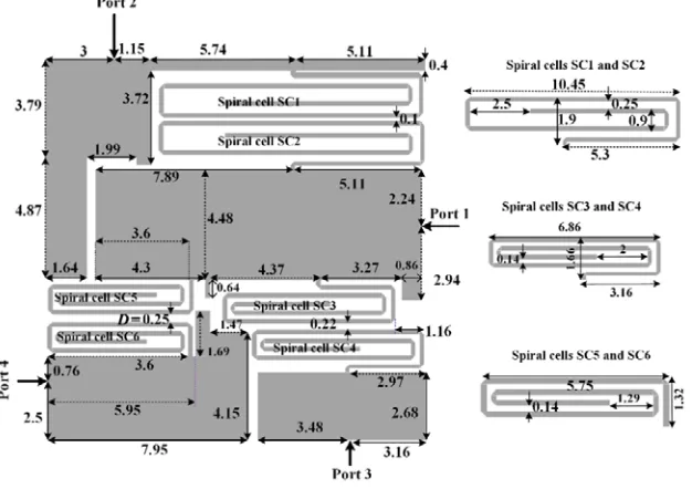
Based on the proposed resonator, a microstrip triplexer can be created. It should consist of three pairs of coupled spirals, integrated by patch cells to create three channels. The layout configuration of the proposed triplexer is presented in Fig. 2, where all dimensions are in mm. Coupled spiral cells are identical, i.e., SC1 with SC2, SC3 with SC4, and SC5 with SC6. The widths of the thin parts of all spirals are 0.2 mm.
Figure 2. Proposed triplexer with its corresponding dimensions in mm.
The surface current density distributions of the designed triplexer at the resonance frequencies are analyzed and depicted in Fig. 3, where Port 1 is the input port (common port), and Port 2, Port 3, and Port 4 are the output ports for the three bands. As shown in Fig. 3, the frequency response is impressed by spiral cells significantly. At the first resonance frequency, the maximum current density distribution is located at spiral cells SC1 and SC2. The spiral cells SC3 and SC4 are important sections at the middle resonance frequency. For the last resonance frequency, the maximum current density is collected in spiral cells SC5 and SC6. Therefore, by adjusting these cells, the channel properties can be improved.
Figure 3. Current density distribution of the designed triplexer at 1.9 GHz, 2.5 GHz, and 3.3 GHz.
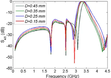
create TZs. In a special frequency, the values of inductors and capacitors can be in such a way that an open circuit is created between the input and output ports. From theLC model of proposed resonator, the equivalent impedance values of the inductor L2 and coupling capacitor at a special frequency can be infinite. At this frequency, we have an open circuit, and it is the frequency of a TZ. This is possible for a low value ofCc. The simulation result of the LC model of coupled lines shows that the coupling capacitors are very small (in fF). Therefore, the coupling capacitors can create TZs. These TZs can be shifted by changing the distances between the coupled lines of the spiral cells. As an example, Fig. 4 shows the effect onS41by changing the distance D, see Fig. 2, between the coupled lines of spiral cells SC5 and SC6.
Figure 4. TZs positions versus the distance (D) between the coupled lines of the spiral cells SC5 and SC6.
3. RESULTS AND DISCUSSION
A full-wave EM simulator in Advanced Design System (ADS) software is used for the simulation of the proposed triplexer. Also, the measurement results are obtained by the Agilent N5230A Network Analyser. The triplexer layout is fabricated on an RT/Duroid 5880 substrate with a thickness of 31 mils, dielectric constant of 2.22, and loss tangent of 0.0009. Fig. 5 shows a photograph of the fabricated triplexer.
Figure 5. Fabricated triplexer.
(a) (b)
(c) (d)
(e) (f)
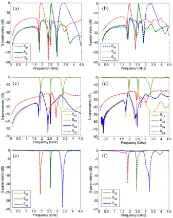
The results show that our triplexer operates at 1.9 GHz (for GSM), 2.5 GHz (for wireless systems), and 3.3 GHz (for IEEE 802.16 WiMAX). The first channel covers 1.85–1.99 GHz with 7.3% fractional bandwidth. The middle channel is from 2.49 up to 2.56 GHz, with 2.5% fractional bandwidth. This channel is suitable for 5G new radio band n7, which covers a 2500 MHz to 2670 MHz frequency range. The last channel has two cutoff frequencies of 3.16 GHz and 3.41 GHz with 9.3% fractional bandwidth. The insertion losses are 0.25 dB, 0.4 dB, and 0.11 dB at the first, second, and third channels, respectively. Very high return losses, more than 40 dB, are obtained in all channels (45 dB at the first band, 54 at the middle band and 40 dB at the last band). Due to both copper loss and junction loss, the measured losses are higher than the simulated losses. The measured insertion losses are 0.75 dB, 0.9 dB, and 0.70 dB at the first, second, and third channels, respectively. The isolations between all channels are better than 20 dB. The harmonics are attenuated up to 4.4 GHz (2.3F1) with a maximum level of −15 dB, where
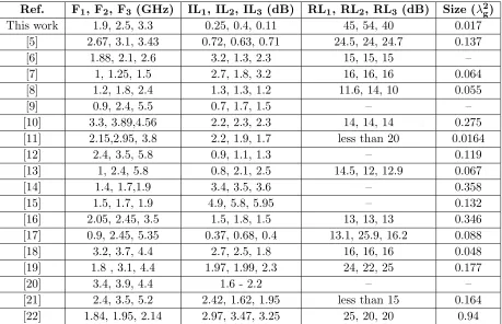
F1 is the first resonance frequency. Accordingly, the designed triplexer can attenuate the 1st, 2nd, and 3rd harmonics. Our triplexer has a very small size of 0.017λ2g (15 mm×15 mm), whereλg is the guided wavelength calculated at 1.9 GHz. As shown in Fig. 6(e) and Fig. 6(f), the simulated return losses from ports 2, 3, and 4 are higher than 20 dB, whereas the measurement results are higher than 18 dB. The insertion losses, return losses, and size of the proposed triplexer are compared with the triplexers in previously published works, see Table 1, where the following abbreviations are used.
Table 1. Comparison between the proposed triplexer and the previous reported triplexers, in terms of insertion losses, return losses, and size.
Ref. F1, F2, F3 (GHz) IL1, IL2, IL3 (dB) RL1, RL2, RL3 (dB) Size (λ2g)
This work 1.9, 2.5, 3.3 0.25, 0.4, 0.11 45, 54, 40 0.017
[5] 2.67, 3.1, 3.43 0.72, 0.63, 0.71 24.5, 24, 24.7 0.137
[6] 1.88, 2.1, 2.6 3.2, 1.3, 2.3 15, 15, 15 –
[7] 1, 1.25, 1.5 2.7, 1.8, 3.2 16, 16, 16 0.064
[8] 1.2, 1.8, 2.4 1.3, 1.3, 1.2 11.6, 14, 10 0.055
[9] 0.9, 2.4, 5.5 0.7, 1.7, 1.5 – –
[10] 3.3, 3.89,4.56 2.2, 2.3, 2.3 14, 14, 14 0.275
[11] 2.15,2.95, 3.8 2.2, 1.9, 1.7 less than 20 0.0164
[12] 2.4, 3.5, 5.8 0.9, 1.1, 1.3 – 0.119
[13] 1, 2.4, 5.8 0.8, 2.1, 2.5 14.5, 12, 12.9 0.067
[14] 1.4, 1.7,1.9 3.4, 3.5, 3.6 – 0.358
[15] 1.5, 1.7, 1.9 4.9, 5.8, 5.95 – 0.132
[16] 2.05, 2.45, 3.5 1.5, 1.8, 1.5 13, 13, 13 0.346
[17] 0.9, 2.45, 5.35 0.37, 0.68, 0.4 13.1, 25.9, 16.2 0.088
[18] 3.2, 3.7, 4.4 2.7, 2.5, 1.8 16, 16, 16 0.048
[19] 1.8 , 3.1, 4.4 1.97, 1.99, 2.3 24, 22, 25 0.177
[20] 3.4, 3.9, 4.4 1.6 - 2.2 – –
[21] 2.4, 3.5, 5.2 2.42, 1.62, 1.95 less than 15 0.164
[22] 1.84, 1.95, 2.14 2.97, 3.47, 3.25 25, 20, 20 0.94
IL1: the first band insertion loss, IL2: the middle band insertion loss, IL3: the last band insertion loss, RL1: the first band return loss, RL2: the middle band return loss, RL3: the last band return loss, F1: the first resonance frequency, F2: the second resonance frequency, and F3: the last resonance frequency.
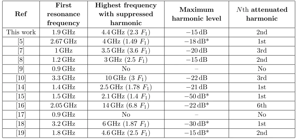
Table 2. Harmonic suppression in comparison with the previous works (*: approximated values).
Ref
First resonance frequency
Highest frequency with suppressed
harmonic
Maximum harmonic level
Nth attenuated harmonic
This work 1.9 GHz 4.4 GHz (2.3 F1) −15 dB 2nd
[5] 2.67 GHz 4 GHz (1.49F1) −18 dB* 1st
[7] 1 GHz 3.5 GHz (3.6 F1) −20 dB 3rd
[8] 1.2 GHz 3 GHz (2.5F1) −15 dB 2nd
[9] 0.9 GHz No – No
[10] 3.3 GHz 10 GHz (3F1) −22 dB 3rd
[14] 1.4 GHz 2.5 GHz (1.78 F1) −21 dB 1st
[15] 1.5 GHz 2.1 GHz (1.4 F1) −50 dB* 1st
[16] 2.05 GHz 14 GHz (6.8F1) −22 dB* 6th
[17] 0.9 GHz No – No
[18] 3.2 GHz 6 GHz (1.87F1) −30 dB* 1st
[19] 1.8 GHz 4.6 GHz (2.5 F1) −15 dB* 2nd
losses/lower return losses than the simulation ones, they are better than the previous works’ results. Only the designed triplexer in [11] is smaller than this work. However, it has very large insertion losses in all channels. The suppressed harmonics of the proposed triplexer are compared with the previous triplexers, and the results are demonstrated in Table 2. As presented in Table 2, some of the previous works’ triplexers such as in [10, 16] and [7] could attenuate the harmonics better than ours. However, they are large and have high insertion loss and low return loss in all channels, as compared with our proposed triplexer. Another advantage of our proposed triplexer is having several transmission zeros (TZs). For port 2, the TZs are located at 1.77 GHz, 2.35 GHz, 2.49 GHz, and 3.36 GHz, with −45 dB,
−60 dB, −45 dB, and −30 dB attenuation levels, respectively. The TZs created by port 3 are: −53 dB at 1.8 GHz, −44 dB at 2.4 GHz, −52 dB at 2.87 GHz, −41 dB at 3.74 GHz, and −44 dB at 4.48 GHz. Moreover, several TZs are created at port 4, i.e., -50 dB at 1.81 GHz, −40 dB at 2.51 GHz, −55 dB at 2.93 GHz, and−43 dB at 4.38 GHz. The frequency selectivity for all channels is improved by these TZs significantly.
4. CONCLUSION
This work presents a high-performance microstrip triplexer with a novel structure and compact size for multi-channel communication systems. The proposed triplexer consists of patch cells and coupled spirals. Due to the use of compact cells, the proposed structure is well miniaturized with an overall size of 15 mm × 15 mm. It has low simulated and measured insertion losses, less than 0.4 dB and 0.7 dB, respectively. Another advantage of this work is the high return losses in all channels. The proposed structure could attenuate the second harmonic. Moreover, it has a sharp frequency response with several TZs, which improve the stopband properties. A good agreement between the measurement and simulation results confirms the performance of the presented triplexer.
REFERENCES
2. Chen, C.-F., T.-M. Shen, T.-Y. Huang, and R.-B. Wu, “Design of compact quadruplexer based on the tri-mode net-type resonators,”IEEE Microw. Wirel. Compon. Lett., Vol. 21, No. 10, 534–536, 2011.
3. Noori, L. and A. Rezaei, “Design of a compact narrowband quad-channel diplexer for multi-channel long-range RF communication systems,”Analog Integrated Circuits and Signal Processing, Vol. 94, No. 1, 1–8, 2018.
4. Hsu, K.-W., W.-C. Hung, and W.-H. Tu, “Design of four-channel diplexer using distributed coupling technique,”Microw. Opt. Technol. Lett., Vol. 58, 166–170, 2016.
5. Rezaei, A. and L. Noori, “Novel low-loss microstrip triplexer using coupled lines and step impedance cells for 4G and WiMAX applications,” Turkish Journal of Electrical Engineering & Computer Sciences, No. 26, 1871–1880, 2018.
6. El-Tokhy, A., R. Wu, and Y. Wang, “Microstrip triplexer using a common triple-mode resonator,” Microw. Opt. Technol. Lett., Vol. 60, No. 7, 1815–1820, 2018.
7. Chen, C.-F., T.-M. Shen, T.-Y. Huang, and R.-B. Wu, “Design of multimode net-type resonators and their applications to filters and multiplexers,” IEEE Trans. Microw. Theory Tech., Vol. 59, No. 4, 848–856, 2011.
8. Jin, X. and Z. Yan, “Microstrip triplexer and switchable triplexer using new impedance matching circuits,”Int. J. RF Microw. Comput. Aided Eng., Vol. 27, e21057, doi:10.1002/mmce.21057. 9. Percaz, J. M., M. Chudzik, I. Arnedo, I. Arregui, F. Teberio, M. A. G. Laso, and T. Lopetegi,
“Producing and exploiting simultaneously the forward and backward coupling in EBG-assisted microstrip coupled lines,”IEEE Antennas Wirel. Propag. Lett., Vol. 15, 873–876, 2015.
10. Tang, C. W. and M. G. Chen, “Packaged microstrip triplexer with star-junction topology,”Electron. Lett., Vol. 48, 699–701, 2012.
11. Huang, Y., G. Wen, and J. Li, “Compact microstrip triplexer based on twist-modified asymmetric split-ring resonators,”Electron. Lett., Vol. 50, 1712–1713, 2014.
12. Wu, H.-W., S.-H. Huang, and Y.-F. Chen, “Compact microstrip triplexer based on coupled step impedance resonator,”IEEE MTT-S International Microwave Symposium Digest (IMS), 2013. 13. Chen, F.-C., J.-M. Qiu, H.-T. Hu, Q.-X. Chu, and M. J. Lancaster, “Design of microstrip
lowpass-bandpass triplexer with high isolation,” IEEE Microw. Wirel. Compon. Lett., Vol. 25, No. 12, 805–807, 2015.
14. Deng, P.-H., M.-I. Lai, S.-K. Jeng, and Ch. H. Chen, “Design of matching circuits for microstrip triplexers based on stepped-impedance resonators,” IEEE Trans. Microw. Theory Tech., Vol. 54, No. 12, 4185–4192, 2006.
15. Lin, S. C. and C. Y. Yeh, “Design of microstrip triplexer with high isolation based on parallel coupled-line filters using T-shaped short-circuited resonators,”IEEE Microw. Wirel. Compon. Lett., Vol. 25, No. 10, 648–650, 2015.
16. Sugchai, T., I. Nattapong, and C. Apirun, “Design of microstrip triplexer using common dual-mode resonator with multi-spurious mode suppression for multiband applications,” Appl. Mech. Mater, Vol. 763, 182–188, 2015.
17. Zhu, C., J. Zhou, and Y. Wang, “Design of microstrip planar triplexer for multimode/multi-band wireless systems,” Microwave J., 1–19, 2010.
18. Wu, J.-Y., K.-W. Hsu, Y.-H. Tseng, and W.-H. Tu, “High-isolation microstrip triplexer using multiple-mode resonators,”IEEE Microw. Wirel. Compon. Lett., Vol. 22, No. 4, 173–175, 2012. 19. Chinig, A., A. Errkik, L. El Abdellaoui, A. Tajmouati, J. Zbitoum, and M. Latrach, “Design
of a microstrip diplexer and triplexer using open loop resonators,” J. Microw. Optoelectron. Electromagn. Appl, Vol. 16, No. 2, 65–80, 2016.
21. Qian, J.-F. and F.-C. Chen, “Wide stopband microstrip triplexer using common crossed, resonator and uniform impedance resonator,”Progress In Electromagnetics Research Letters, Vol. 69, 79–86, 2017.
22. Rebenaque, D. C. and G. Macchiarella, “Application of polynomial design of multiplexers to the implementation of a manifold microstrip triplexer,” Int. J. RF Microwave Comput. Aided Eng., Vol. 23, No. 6, 690–698, Oct. 2013.
23. Rezaei, A. and L. Noori, “Novel compact microstrip diplexer for GSM applications,”Int. J. Microw. Wirel. Technol., Vol. 10, No. 3, 313–317, 2018.