Volume 2008, Article ID 427247,13pages doi:10.1155/2008/427247
Research Article
Feedback Channel Suppression in Distributed Video
Coding with Adaptive Rate Allocation and Quantization for
Multiuser Applications
Charles Yaacoub,1, 2Joumana Farah,1and B ´eatrice Pesquet-Popescu2
1Department of Engineering, Faculty of Sciences and Computer Engineering, Holy-Spirit University of Kaslik, P.O. Box 446, Jounieh, Lebanon
2Signal and Image Processing Department, TELECOM ParisTech, 46 Rue Barrault, 75634 Paris Cedex 13, France
Correspondence should be addressed to Charles Yaacoub,[email protected]
Received 8 January 2008; Accepted 18 September 2008
Recommended by Kameswara Namuduri
We present a novel rate allocation technique for distributed multiuser video coding systems without the need for a permanent feedback channel. Based on analytical calculations, the system unequally distributes the available bandwidth among the different users, taking into account the actual amount of movement in the transmitted video as well as the transmission conditions of each user. On one hand, the quantization parameters are dynamically tuned in order to optimize the decoding quality. On the other hand, a frame dropping mechanism allows the system to avoid unnecessary channel use, when the analytical estimations show that the successful decoding of a given frame is not possible because of very high motion or bad channel conditions. A significant gain in the system performance is noticed compared with the case of equal allocation of channel resources and constant quantization parameters.
Copyright © 2008 Charles Yaacoub et al. This is an open access article distributed under the Creative Commons Attribution License, which permits unrestricted use, distribution, and reproduction in any medium, provided the original work is properly cited.
1. INTRODUCTION
During the last decade, distributed source coding has made a tremendous progress, especially in the world of video communications [1–13]. In traditional video coding techniques such as MPEG or H.26x [14], motion estimation is performed at the encoder side in order to transmit motion information to the decoder, which yields very complex inter-frame encoders. At the decoder side, motion compensation is performed based on the received information, thus result-ing in simple decoders. This configuration (i.e., complex encoders and simple decoders) is suitable for applications where a video scene is encoded once in a base station with sufficient resources, and decoded several times. Video broadcasting and video streaming on demand are the most common examples for this configuration; video sequences are compressed and stored on a server, and then streamed to multiple users, upon request for video on demand. A low-complexity decoder is desired in such applications in order to permit low-cost receivers for the end-users.
However, in other situations, a simple encoder is desired. Distributed video coding (DVC) was introduced [7,8] to permit low-complexity encoding for small power-limited and memory-limited devices, such as camera-equipped mobile phones or wireless video sensors (see Figure 1), by moving the computation burden from the encoder side to decoder’s. In such scenarios, the decoder is assumed to be located in a base station with sufficient resources.
It is known from information theory that, given two statistically dependent sources X and Y, each source can be independently compressed to its entropy limitH(X) and
H(Y), respectively. However, by exploiting the correlation between the two sources,XandYcan be jointly compressed to the joint entropy H(X,Y). This results in a reduced total transmission rate since H(X,Y) ≤ H(X) + H(Y). The idea behind DVC goes back to the 1970’s when Slepian and Wolf proved in [15] that, if Y is compressed to its entropy limit H(Y), X can be transmitted at a rate very close to the conditional entropyH(X | Y), provided that
Since H(X,Y) = H(Y) + H(X | Y), X and Y can be independently encoded and jointly decoded without any loss in the compression efficiency, compared to the case where both sources are jointly encoded and decoded. The application of this concept to lossy source coding is known as the Wyner-Ziv coding [16].
In practical DVC systems [6–9], a subset of frames, known as key frames, is usually compressed using traditional intracoding techniques. One or more frames following each key frame, known as Wyner-Ziv (WZ) frames, are then compressed by appropriate puncturing of the parity bits at the output of a channel coder. At the receiver side, key frames are interpolated to generate the necessary side information for the decoding process.
One of the first practical DVC systems proposed by Puri and Ramchandran [7] used syndrome encoding. In [8], Aaron et al. used turbo codes [17–19] for the compression of WZ frames. Later on, Ascenso et al. [10] proposed a refined motion compensation technique to generate more efficient side information for the system in [8]. One of the main drawbacks in all these systems is the use of a feedback channel (FC) [11] to allow flexible rate control and to ensure successful decoding of WZ frames. The FC is not suitable for real-time systems due to transmission delay constraints. Additionally, in multiuser applications with rate constraints, the application of WZ coding becomes impracti-cal because of the difficulty of implementing appropriate rate allocation algorithms. Furthermore, since several decoding runs are required to successfully recover a WZ frame, the FC imposes instantaneous decoding in the receiver. For all these reasons, the introduction of new techniques for estimating the necessary bitrate to successfully decode each WZ frame becomes crucial. In fact, the problem of the return channel in DVC has rarely been targeted in the literature. A simple technique that allows the removal of the FC was proposed by Artigas and Torres in [12]. The necessary compression rate of a given frame was estimated based on empirical results. This estimation requires building performance tables for the channel code in use, for all possible compression rates and correlation levels between the side information and the WZ frames in a given sequence. Such tables can be built by running offline simulations. However, the influence of the transmission impairments on the decoding performance is not considered. In this case, performance tables should be built not only for all possible correlation levels and compression rates, but also for all possible channel states. This results in a significantly large (theoretically infinite) number of tables that cannot be stored in memory-limited devices. Thus, the proposed technique cannot be used in practical real-time applications with video sequences containing different levels of motion or transmitted over time-varying wireless channels. Morbee et al. [13] proposed another technique for the removal of the feedback channel in DVC. First, the correlation between a WZ frame and the corresponding side information is modeled by a binary symmetric channel (BSC) with a different transition probability for each bitplane. Then, the performances of the channel code in use are estimated offline as a function of the transition probabilities using random
binary sequences. The compression rate for a given frame is then determined based on the two previous estimations. This technique presents several disadvantages as well. First, it does not take into consideration the rate constraints in limited bandwidth applications. Besides, when the WZ frame is decoded with a high error rate, the decoded data is discarded in the receiver and replaced by the available side information, yielding wasted channel use. Furthermore, the influence of the channel impairments on the proposed rate allocation technique is not considered. Moreover, both techniques are designed for a single-user scenario; their implementation in a multiuser application would cause unoptimal distribution of the channel resources between the different users since each user tends to occupy the necessary bandwidth for its own transmission regardless of the total available bandwidth and of the needs of the other transmitting users.
In this paper, we present a novel technique for the removal of the feedback channel in DVC systems, using an analytical approach based on entropy calculations. Designed for a multiuser scenario, the proposed technique takes into account the amount of motion in the captured video scene as well as the transmission channel conditions for every user, in order to allocate unequal transmission rates among the different users. On the other hand, the total transmission rate for all users does not exceed a fixed, maximum allowable rate imposed by the limited available bandwidth in such systems. Furthermore, the quantization parameter (i.e., the number of quantization levels) is dynamically varied for each frame, at every user, in such a way to optimize the decoded video quality. A frame dropping mechanism is also used in order to avoid unnecessary channel use, when the analytical estimations show that successful decoding of a given WZ frame will not be possible in the receiver because of very high-motion and/or bad channel conditions.
This paper is organized as follows. In Section 2, we present a detailed description of the DVC codec. The theo-retical compression bound for the distributed video coding system is then determined in Section 3. Modified turbo decoding metrics are derived inSection 4and the proposed rate allocation technique is then presented in Section 5. Finally, simulation results are reported inSection 6.
2. DESCRIPTION OF THE MULTIUSER VIDEO CODING SYSTEM
Consider a network ofNvideo users as shown inFigure 1. In practical applications, these users can be camera-equipped mobile phones, each capturing a different scene, or wireless surveillance cameras capturing the same scene from different viewpoints. Each user transmits the video data to a central base station through a different wireless channel. The base station performs rate control based on each user’s transmission conditions and on the amount of movement in each video scene, as will be detailed later.
Base station Rate control Channel 1
Channel 2 ChannelN
User 1
User 2 UserN
Scene 1
Scene 2 SceneN
Figure1: Network of wireless video sensors.
generated by motion-compensated interpolation of the two adjacent odd frames, with symmetric motion vectors [8]. As for the compression of the even frames, it starts by a uniform scalar quantization to obtain anM-bit representation of the eight-bit pixels, where M ∈ {1, 2, 4}. Quantized pixels are then serially concatenated and fed to the source-channel turbo encoder shown in Figure 3; it consists of a parallel concatenation of two 16-state quadri-binary convolutional encoders separated by an internal interleaver and resulting in a minimum global coding rate of 2/3. The generator polynomials in octal notation are (23, 35, 31, 37, 27)8
from [20]. At the encoder output, systematic information is discarded, while parity information is punctured and transmitted to the decoder.
The amount of puncturing is determined by the desired compression rate for each frame. In case of error-free transmission, turbo coding and puncturing are performed only to achieve source compression. However, for a trans-mission through a noisy channel, error-protection is also desired, yielding joint source-channel coding. In this study, we model the transmission channel between each user and the base station by a binary symmetric channel (BSC) with a transition probabilityq. In fact, a different channel model (e.g., additive white Gaussian noise or Rayleigh fading) can also be used in our system by a mapping to a BSC [5,6] using an equivalence of the stability functions as detailed in [21].
As stated earlier, quantized pixels of the even (WZ) frames are serially concatenated and fed to the turbo encoder. In other words, in our system, no bitplane extraction [8– 13] is performed. Aaron et al. mentioned in [9] that both techniques (serial concatenation and bitplane extraction) yield similar results. However, we have noticed that bitplane coding presents a major disadvantage in case the FC is sup-pressed; since the necessary compression rate to successfully decode a given bitplane cannot be determined without a return channel, the compression of a certain bitplane cannot begin until the parity bits corresponding to the previous bitplane have all been transmitted. In fact, this procedure guarantees the least compression on the most significant bits (MSBs) in the quantized pixels, and the strongest
compression on the least significant bits (LSBs). However, in the absence of a return channel, a very strong compression on a bitplane can lead to a high decoding bit error rate (BER) and, consequently, a bad reconstructed output. If the compression was slightly stronger on the MSBs and softer on the LSBs, while keeping the same average compression rate per pixel, the system error correction capability would often yield a better result. This can be performed by directly feeding the quantized pixels to the turbo encoder instead of extracting bitplanes. Additionally, the use of a quadri-binary turbo codec, by a serial concatenation of the quantized pixels at the encoder input, allows for nonbinary turbo coding, which yields improved decoding performances compared to binary coding [4].
In the joint source-channel decoder, the conditional probabilities in the turbo decoding process must depend on the residual signal statistics between the even frames and the side information on one hand, and on the channel conditions on the other. In the sequel, we will derive the proper metric calculations for the turbo decoding process.
Finally, the reconstruction block is used to recover an eight-bit version of the even frames using the available side information [8].
3. THEORETICAL COMPRESSION BOUND OF THE JOINT SOURCE-CHANNEL DISTRIBUTED VIDEO CODEC
In case of error-free transmission, the Slepian-Wolf theorem states that a WZ frame can be compressed to a rate close to the conditional entropyH(X|Y) defined as
H(X|Y)= −
2M−1
a=0 2M−1
b=0
P(Y=b)
×PX=a|Y=blog2PX=a|Y =b, (1)
where M is the number of quantization bits per pixel, X
represents the quantized WZ frame, and Y represents the interpolated side information. The statistics of the residual error between the side information and the WZ frame are modeled by a Laplacian distribution [8] with parameterα:
P(X−Y=Δ)=c
α
2
e−α|dΔ|, (2)
wheredΔ=2(8−M)Δandcis a normalization factor such that
ΔP(X−Y =Δ)=1. Obviously,P(X−Y)=P(Y−X). The parameterαcan be approximately estimated on the receiver side using the available odd frames. It can also be estimated by the encoder and transmitted as side informa-tion to the receiver. In the latter case, no moinforma-tion estimainforma-tion is required at the encoder side; an average interpolation can be performed on the odd frames to approximate the side information generated at the receiver, and the variance σ2
Video sequence
Even frames
Odd frames
Quantization
Intra-coding
Intraframe encoder
Interframe decoder Slepian-Wolf codec
Joint source-channel encoder BSC
Joint
source-channel decoder Reconstruction
Interpolation Quantization
Intra-decoding
Video sequence
Figure2: Block diagram of the pixel-domain distributed video coding system.
xsik
i=1, 2, 3, 4
Internal interleaver
Quadri-binary encoder #1
Quadri-binary encoder #2
xsik
i=1, 2, 3, 4 Systematic information
x1pk Encoder #1parity bit
x2pk Encoder #2 parity bit Figure3: Quadri-binary turbo encoder.
On the other hand,
P(X−Y=Δ)=
b
P(X=a=Δ+b|Y=b)P(Y=b).
(3)
The number of nonzero terms in (3) is equal to the number
Lda−b of couples (a,b) that yield the residual difference
Δ = a − b. Supposing an equiprobable source, these couples can be considered to be equally likely; for example, considering a two-bit quantization, the possible values of
Δare 0,±1,±2, and±3 (i.e.,dΔ=0,±64,±128, and±192), with a decreasing order of probability of occurrence. For a particular value of the difference Δ, couples (a,b) that yield the differenceΔhave the same probability to occur. For example, forΔ=1, the occurrences of (a=1,b=0), (a=2,
b =1), and (a =3,b=2) are equally likely. Therefore, we can write
P(X=a|Y=b)= 2M
LdΔ
P(X−Y =Δ), (4)
whereΔ=a−b. By calculatingLdΔfor different values ofΔ,
we found thatLdΔ=2
M− |d Δ|.
Besides, it can be easily shown thatP(X | Y) = P(Y | X). In fact, sinceP(X−Y)=P(Y−X) (from (2)),|dΔ| =
|2(8−M)Δ| = |2(8−M)(−Δ)| = |d
−Δ|, andLdΔ =2
M− |d Δ| =
Ld−Δ, we have
P(Y=b|X=a)= 2M
Ldb−a
P(Y−X=b−a)
= 2M Lda−b
P(X−Y =a−b)
=P(X=a|Y=b).
(5)
Finally, combining (1), (2), and (4) yields
H(X|Y)
= − 2M−1
a=0 2M−1
b=0 cα
2
e−α|da−b| Lda−b
log2
c2
M−1αe−α|da−b|
Lda−b
.
(6)
LetHf(M) be the theoretical lower compression bound for a video frame f transmitted in the absence of noise, expressed as in (6). Since the transmission channel between a user and the base station is modeled by a BSC with a transition probability q, the overall theoretical compression bound becomes [1]
Hf(M)=
Hf(M)
C(q) , (7)
whereC(q) is the capacity of the BSC defined as
In the presence of transmission errors, the Wyner-Ziv codec performs joint source-channel coding. Equation (7) shows that, by considering channel impairments, the compression bound increases as the channel noise increases (Hf(M) ≥
Hf(M) since 0≤ C(q)≤ 1). On the other hand, it can be verified that in the absence of channel errors, since no error protection is needed and C(q) = 1, (7) reduces to (6) as expected.
4. JOINT SOURCE-CHANNEL TURBO DECODING
Turbo decoding is realized by iterative soft-input soft-output (SISO) decoders based on the Max-Log-MAP (maximum a posteriori) algorithm [22]. However, since nonbinary codes are used in this work, we modified the metric calculations in order to take into account all possible transitions between any couple of trellis states. Moreover, the conditional prob-abilities in the turbo decoding process must rely on the residual signal statistics between the even frames and the side information on one hand, and on the channel conditions on the other.
As for the turbo decoding algorithm, we chose the Max-Log-MAP algorithm in order to reduce the decoding complexity. Note that the MAP or Log-MAP [22] algorithms could also be used. However, the gain in performance would be slight compared to the important increase in the decoding complexity.
Let{xs1k,xs2k,xs3k,xs4k}be a group of four systematic bits at the input of the turbo encoder at time instant k, and {x1pk,x2pk} the corresponding output parity bits from the first and second encoders, respectively (see Figure 3). Let {y1pk,y
p
2k}be the received noisy versions of the parity bits at the output of the BSC with transition probability q. Since only parity bits are transmitted by the Slepian-Wolf encoder, the decoder replaces the missing systematic bits with their corresponding side information{ys
1k,ys2k,y3sk,y4sk}generated using the key (i.e., odd) frames.
During the turbo decoding process, each constituent convolutional decoder needs to determine the conditional probability: represents the order of the constituent encoder,i=1 or 2.
In the case where the quantization parameterM=4, the four systematic bits at the turbo decoder input correspond to one quantized pixel from the interpolated frame.
LetX =8xs1k+ 4x2sk+ 2xs3k+xs4kbe the bin index of the quantized pixel in the WZ frame, and Y = 8ys1k+ 4ys2k+
2y3sk+y4skthe bin index of the corresponding quantized side information. Using (4), we can write
Py1sk,ys2k,y3sk,ys4k|x1sk,x2sk,xs3k,xs4k
In the case where M = 2, the four systematic bits correspond to two quantized pixels.
LetX1 =2x1sk+x2sk andX2 =2x3sk+x4sk be the bins of the two WZ quantized pixels with their corresponding side informationY1=2ys1k+y2skandY2=2ys3k+y4sk. Therefore,
WhenM =1, each systematic bit corresponds to one pixel. LetXi = xiks be the bin index of the quantized pixeli(i =
k|xks) has been determined for all possible values ofM, we can proceed with the calculation ofP(ykp | x
p k) in (9).
First, let Ppunct(ρ) be the probability of puncturing a parity bit expressed as a function of the compression rate
ρfor the current WZ frame.ρis defined as the ratio of the number Np of remaining parity bits after puncturing over the total number of systematic bits Ns. Since the number of parity bits at the turbo encoder output is Ns/2 before puncturing, we get
Two cases have to be considered for the calculation ofP(ykp|
xkp) at the decoder.
Case 2. xkphas not been punctured at the output of the turbo encoder. In this case,ykpcan take two possible values: 0 or 1. Therefore,
On the other hand,
Pykp|x
k is not punctured
k is not punctured
On the other hand, the extrinsic information on a symbol
dk=xskis given by
Therefore, it is easy to prove that [23]
lnPdk=0
On the other side, the logarithmic branch metric from state
sto states, in the code trellis at timek, can be calculated by
As for the forward and backward state metrics, they are given by
On the other hand, the log-likelihood ratio of symboldk is calculated using
Finally, the extrinsic information used as a priori informa-tion to the next decoder is calculated by
Lai measure of the channel reliability [18].
At the end of each decoding iteration, 15 LLRs are calculated for each symbol dk. At the last iteration, dk is decoded as
0 otherwise. (25)
5. ADAPTIVE RATE ALLOCATION AND QUANTIZATION TECHNIQUE
Consider a system of N users sharing the same wireless medium to transmit video data to a base station at a total bitrate ofRbits per second (bps). Letρf,nbe the compression rate for frame f at nodendefined as inSection 4,Mf,nthe quantization parameter for this frame, andAf,n=Mf,n·ρf,n its average number of bits per pixel. In our joint source-channel codec, if no parity bits are transmitted,ρf,n=0. On the other side, if all parity bits are transmitted without any puncturing,ρf,n=1/2. As a result, the compression rate can be varied between these two extreme cases: 0≤ρf,n ≤1/2. Our aim is to determine, for each frame f at every usern, the couple (Mf,n, ρf,n) that optimizes the average system performance. In other words,
encoded at the user n. PSNRf,n depends not only on the parameters Mf,n and ρf,n, but also on the transmission conditions, the accuracy of the side information, and the rate constraint:
N
n=1
Rf,n≤R, (27)
whereRf,nis the transmission rate assigned for the frame f at the user n. As a result, it is difficult to solve analytically
(26) for the set{(Mf,n,ρf,n); n=1,. . .,N}. For this reason, we proceed with the optimization process in two stages. First, we determine the transmission rate for each user, and then we choose the couples (Mf,n,ρf,n) that yield the best reconstructed output at the specified bitrates.
In the first stage, instead of assigningR/N bps for each user, the base station first determines the compression bound for each frame as in (7), based on its content (parameterα) and on the user transmission conditions (channel crossover probability q). Since the optimal quantization parameter has not been determined yet, (7) is calculated forM = 8, assuming eight-bit raw video data before compression. Then, in a proportionally fair attribution, the usernis assigned the rate
Rf,n=
Hf,n(8) N
n=1Hf,n(8)
R, (28)
where Hf,n(8) represents the entropy in (7) calculated for frame f at nodenwithM=8.
The average number of bits per pixelAf,n is related to
Rf,nby
Af,n=
Rf,n
m·n·r, (29)
where (m,n) represent the dimensions of a given frame, and
rthe WZ frame rate (in fps).
In the second stage, the base station needs to determine, for each frame f at every node n, the couple (Mf,n,ρf,n) that yields the best video output after reconstruction, at the specified rateRf,n. In fact, this is equivalent to optimizing the individual rate-distortion performance for each user since, for a given bitrate, the parameters are chosen in such a way to maximize PSNRf,n.
After a thorough analysis of the system performance observed for different values ofMf,n, we noticed that in most cases, for a given target bitrate, choosing the lowest allowable value of Mf,n yields the best video quality at the decoder output. Indeed, by reducing the number of quantization levels, the system is able to transmit a greater amount of parity bits to protect the quantized bitstream from channel errors, especially whenqincreases. However, in some cases, the assigned bitrate is sufficient enough to permit efficient error protection when a greater value of Mf,n is selected; thus, a better reconstructed output can be obtained. In all cases, we noticed that the system behavior for different configurations of the couples (Mf,n,ρf,n) is directly related
to the ratio between Af,n and the theoretical compression bound defined as
Cf,n
Mf,n
= Af,n Hf,n
Mf,n
. (30)
Therefore, we define the thresholds T1,T2, and T4 which indicate the average value of the ratioCf,n(Mf,n) that permits a correct decoding of a transmitted frame for Mf,n = 1, 2, and 4, respectively. These thresholds are determined experimentally by observing the system performance for different values of the ratioCf,n(Mf,n), as will be detailed in Section 6. Our proposed algorithm then proceeds with the dynamic quantization (seeFigure 4) as follows.
Step 1. Initially, setMf,nto the lowest value that permits to reachAf,n. This will allow for the maximum error protection for a givenAf,n.
Step 2. CalculateCf,n(1),Cf,n(2), andCf,n(4).
Step 3. If M = 4 and Cf,n(4) ≤ T4, set Mf,n = 2 and
ρf,n = 1/2. In other words, if Af,n could not be reached for Mf,n < 4 (i.e., Af,n > 1) and the amount of error protection transmitted with Mf,n = 4 does not yield an acceptable decoding error rate, set Mf,n to the next lower value and transmit all parity bits. In this case, the given frame is transmitted at a rate lower than the target bitrate since the targetAf,ncould not be reached exactly. Similarly, ifMf,n=2 andCf,n(2)≤T2, setMf,n=1 andρf,n=1/2.
Step 4. IfMf,n = 1 andCf,n(1) ≤ T1, drop the frame (set
Mf,n =0). In this case, the amount of transmitted bits will not permit efficient decoding even if the number of quan-tization levels is reduced to its minimum. At the decoder, the dropped frame is replaced by the corresponding side information. Note that other error concealment techniques can also be envisaged in the receiver.
Step 5. IfMf,n=1 andCf,n(2)> T2, setMf,n=2. In other words, ifAf,n is reachable with Mf,n = 1 and 2, and it is possible to send a sufficient amount of parity bits to correctly decode the frame withMf,n=2, setMf,n=2 since it yields a better reconstructed output. Similarly, if Mf,n = 2 and
Cf,n(4)> T4, setMf,n=4.
Step 6. If the frame was not dropped andρf,nwas not already set to 1/2, setρf,n=Af,n/Mf,n.
Step 7. Transmit the couple (Mf,n,ρf,n) to the corresponding user.
Af,n= Rf,n m·n·r
Af,n≤0.5 No Af,n≤1 No Yes
SetMf,n=1
Yes
SetMf,n=2 SetMf,n=4
Cf,n(Mf,n)= Af,n Hf,n(Mf,n)
Mf,n=4, Cf,n(4)≤T4
No
Yes SetMf,n=2,
ρf,n=1/2
Mf,n=2, Cf,n(2)≤T2
No
Yes SetMf,n=1,
ρf,n=1/2
Mf,n=1, Cf,n(1)≤T1
No Mf,n=1, Cf,n(2)> T2
No
Yes Drop the frame
Yes SetMf,n=2
Mf,n=2, Cf,n(4)> T4
No
Yes SetMf,n=4
ρf,n=1/2 No
Yes ρf,n= Af,n Mf,n
End the dynamic quantization process
Figure4: Dynamic quantization algorithm with a frame dropping mechanism.
1700 1200
700 200
Total bitrateR(kbps) TRD,M=1
TRD,M=2 TRD,M=4
ARA,M=1 ARA,M=2 ARA,M=4 36
37 38 39 40 41
A
ver
age
P
SNR
(dB)
Figure5: R-D curves obtained with a TRD system and with the ARA technique.
6. EXPERIMENTAL RESULTS
In our simulation setup, we consider a set of three mobile users (N = 3) capturing different scenes and transmitting the resulting video to a central base station. These scenes are assumed to be the Foreman, Carphone, and Mother-Daughter QCIF video sequences. They are sampled at a rate of 15 WZ frames per second (fps), which corresponds to an overall sampling rate of 30 fps. For example, this can be seen as a network of surveillance cameras in a building, each located in a different floor, or a network of mobile users positioned at different locations in a cell. We consider the first 100 frames of each sequence repeated in 50 simulations. The side information is generated by motion-compensated interpolation with symmetric motion vectors as described in [8]. The time-varying nature of the transmission channel between a video user and the base station is modeled by a uniform random variation of the crossover probability q
between 0.001 and 0.02, independently for each user. In Figure 5, we first show the rate-distortion (R-D) curves obtained with a traditional (TRD) system where all users are assigned an equal bandwidth. The quantization parameterMis fixed and is the same for all users. The results are presented in terms of the PSNR averaged over the three video scenes as a function of the total WZ bitrate occupied by all the users. We also show the results obtained with our adaptive rate allocation (ARA) technique (see (28) and (29)), but with a constant quantization parameter. We can clearly see that when the rate regions overlap for different values of
1700 1500
1300 1100
900
Total bitrateR(kbps) TRD (D)
ARA (D) ARA (F)
ARA (C) TRD (F) TRD (C) 33
35 37 39 41 43 45
A
ver
age
P
SNR
(dB)
Figure6: Individual PSNR as a function of the total bitrate, for the Carphone (C), Foreman (F), and Mother-Dauther (D) sequences, withM=4.
In some cases, the performance of a TRD system can be better than that of ARA. In Figure 6, we present the individual PSNR of the different video sequences, for the case whereM = 4. In fact, a similar behavior is observed for different values ofM. We notice that at a total bitrate of 1 Mbps, the performance loss for the Mother-Daughter (D) sequence is relatively high, which degrades the average ARA system performance, compared to the TRD system, as also shown inFigure 5. The remedy for this problem is to reduce the number of quantization levels for the transmission at this bitrate, as was explained earlier. We also notice that the ARA technique significantly improves the PSNR of the Carphone (C) and Foreman (F) sequences at the expense of a reduced performance for Mother-Daughter. This can be explained by the fact that the Mother-Daughter sequence contains low-motion scenes, while Carphone and Foreman are characterized by average and high-motion scenes. In fact, the ARA technique allocates the lowest rates for videos with low motion and/or experiencing good channel conditions, while the highest rates are assigned to video users capturing high-motion scenes and/or suffering from a bad channel. This results in an improved average system performance, especially at medium and high total transmission rates.
The analysis of the individual PSNR as a function of the total bitrate (as inFigure 6) can sometimes be misleading. InFigure 7, the PSNR of each video sequence is represented as a function of the effective WZ bitrate assigned for each user, for the case where M = 4. Figure 7 clearly shows that the R-D curves obtained with the ARA technique are above those obtained with a TRD system. This implies that the ARA technique improves not only the average system performance, but the individual R-D performance for each user as well, especially at medium and high bitrates.
This effect can be further explained by Table 1 which shows the average bitrates (in kbps) assigned for each user with the ARA technique. In the TRD system, all users operate
700 600
500 400
300 200
Individual bitrateR(kbps) ARA (D)
TRD (D) ARA (F)
TRD (F) ARA (C) TRD (C) 33
35 37 39 41 43 45
A
ver
age
P
SNR
(dB)
Figure7: Individual R-D curves for the Carphone (C), Foreman (F), and Mother-Dauther (D) sequences obtained withM=4.
at the same bitrate. Indeed, we notice that in all cases, for a certain total bitrate, the ARA technique assigns the Mother-Daughter sequence the lowest bitrate compared to the two other sequences. For example, at a total rate of 1.5 Mbps, the bitrate assigned for Mother-Daughter is almost half the one assigned for Carphone. Moreover, the bitrate assigned for the Mother-Daughter sequence by the ARA technique is less than the one assigned by the TRD system. This allows the assignment of higher bitrates to the two other sequences, and leads to an improvement in the overall system performance.
In order to apply the dynamic quantization algorithm and the frame dropping mechanism, it is necessary to determine suitable values for the thresholds T1, T2, and
T4 defined in Section 5. For this purpose, we show, in Figure 8, the BER obtained after source-channel decoding, as a function of the ratioCf,ndefined in (30). For each value ofM, the transmission of 22500 frames from different video sequences was simulated with variable channel conditions. In general, a BER close to 10−3 is desired to yield a
good reconstructed output [8]. When M = 1, only the most significant bit in each pixel is coded and transmitted, which greatly affects the performance of the reconstruction function. For this reason, we chose a threshold T1 = 6 to guarantee a BER less than 10−3 in this case. Similarly, we choseT2 =4 for a BER of 10−3whenM =2. For the case whereM =4, a higher BER can be tolerated since the two least significant bits in the quantized pixel are less important than the two most significant bits. Therefore, we choseT4= 2.4. In the sequel, we will show the system performances for these selected values of the thresholds, and compare them to the ones obtained with other values ofT2andT4.
Table1: Average individual bitrates in kbps for the Carphone (C), Foreman (F), and Mother-Dauther (D) sequences.
Total TRD ARA (C) ARA (F) ARA (D)
M=1
249.5 83.16 80.1 95.5 73.9
320.8 106.92 103.2 124.4 93.2
392 130.68 127.6 150.5 113.9
M=2
499 166.32 212.9 168.3 117.7
641.5 213.84 274.2 219.9 147.4
784.1 261.36 331.1 274.4 178.6
M=4
997.9 332.64 405.4 353.4 239.2
1283 427.68 520.3 461.9 300.8
1568.2 522.72 636.5 568.5 363.1
9 7
5 3
1
Ratio M=1
M=2 M=4 1E−06
1E−05 1E−04 1E−03 1E−02 1E−01 1E+ 00
BER
Figure8: Performance curves showing the BER as a function of the ratio in (30) forM=1, 2, and 4.
algorithm is skipped), a performance gain towards the TRD system is observed only at high rates, forT2 = T4 = 2.7. The reason for this behavior is that, at low rates, M takes the values 1 or 2 most of the time andT2 = 2.7 does not guarantee a good BER whenM = 2, as shown inFigure 8, whereas forM = 4 (mostly at high rates),T4 = 2.7 yields acceptable performance. Compared to the TRD system, very close performances are obtained at low rates by settingT2= 4 andT4=2.4, while an important enhancement is noticed at medium and high rates. In fact, at very low rates, the available bandwidth to be allocated for the different users is barely sufficient to protect the transmitted bitstreams. At a rate near 200 kbps, we notice a performance loss of 0.5 dB, whereas a gain of 1.5 dB is observed with the frame dropping mechanism (ARAQ-D curves) forT1 = 6. When the bitrate increases, less frames are dropped. Starting from 600 kbps, the R-D curves are the same with or without frame dropping. This is expected since frames are only dropped when the assigned bitrate is not sufficient to guarantee a correct decoding of the transmitted WZ frame. On the other hand, at 500 kbps, our proposed algorithm yields similar performance compared to the TRD system withM=1, but
1700 1450 1200 950
700 450 200
Total bitrateR(kbps) TRD,M=1
TRD,M=2 TRD,M=4 ARAQ:T2=T4=2.7
ARAQ:T2=4,T4=2.4
ARAQ-D:T1=6,T2=4,T4=2.4
ARA,M=1 ARA,M=2 ARA,M=4 36
37 38 39 40 41
A
ver
age
P
SNR
(dB)
Figure9: R-D Curves obtained with a TRD system and with the ARAQ and ARAQ-D techniques.
a gain of 1.4 dB is observed towards the case whereM = 2. At 1 Mbps, the gain reaches 0.6 dB compared toM =2 and 1.5 dB toM=4.
It is important to note that whenM is fixed (TRD and ARA systems), the transmission bitrate for the WZ codec is limited to a narrow range. For example, a traditional system with N = 3 cannot transmit at a total rate greater than 570 kbps whenM = 1, and 1140 kbps when M = 2 (assuming QCIF video sequences sampled at 15 WZ-fps). Our proposed algorithm with the ARAQ and ARAQ-D techniques allows the system to transmit video data at a wider range of transmission rates and with an optimized decoding quality.
640 440
240 40
BitrateR(kbps) ARAQ-D (C)
TRD (C)M=1
TRD (C)M=2 TRD (C)M=4 32
33 34 35 36 37 38 39 40
PSNR
(dB)
Figure 10: R-D curves for the Carphone (C) sequence obtained with the ARAQ-D technique, compared to the performance of a TRD system.
640 440
240 40
BitrateR(kbps) ARAQ-D (F)
TRD (F)M=1
TRD (F)M=2 TRD (F)M=4 35
36 37 38 39 40
PSNR
(dB)
Figure11: R-D curves for the Foreman (F) sequence obtained with the ARAQ-D technique, compared to the performance of a TRD system.
assigned a maximum of 615 kbps and 610 kbps, respectively. The unequal assignment of channel resources with the proposed rate allocation techniques (ARA, ARAQ, and ARAQ-D) results in an improvement in the overall system performance.
In our simulations, key frames were assumed to be perfectly recovered at the receiver. The case where key frames are subject to degradations due to lossy source coding or channel impairments can be easily taken into account in our study by modifying the entropy calculations inSection 3 accordingly. However, it should be noted that, in this case, all studied systems (TRD, ARA, ARAQ, and ARAQ-D) would be subject to a similar performance degradation. As a result, the performance analysis presented earlier would still hold.
540 440
340 240
140 40
BitrateR(kbps) ARAQ-D (D)
TRD (D)M=1
TRD (D)M=2 TRD (D)M=4 40
41 42 43 44 45
PSNR
(dB)
Figure 12: R-D curves for the Mother-Daughter (D) sequence obtained with the ARAQ-D technique, compared to the perfor-mance of a TRD system.
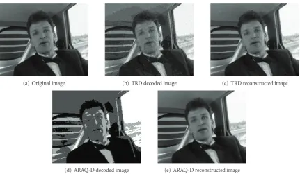
In Figure 13, we show a snapshot from the Carphone video sequence (7th WZ frame) obtained with both the TRD (FiguresFigure 13(b)andFigure 13(c)) and ARAQ-D (Figures13(d) and13(e)) systems, for the same transmission conditions (Rf,n=332.64 kbps andq=6.4·10−3). The mid-dle column shows the turbo decoded images before recon-struction, and the right column shows the final reconstructed outputs. In the TRD system, the quantization parameter was set toMf,n=4 and the compression rate toρf,n=0.21875, whereas the ARAQ-D system determined thatMf,n=2 and
ρf,n=0.4375 would yield a better result, even though in both casesAf,n = 0.875. In fact, whenMf,n = 4, more details about the transmitted image are available at the receiver, as shown inFigure 13(b)compared toFigure 13(d). This is supposed to help the reconstruction function in improving the output video quality. However, the received frame was decoded with BER=0.09 in the TRD system, giving a noise-like visual effect (seeFigure 13(b)), whereas in the ARAQ-D system, the frame was perfectly recovered (BER≈0) with
Mf,n = 2 (see Figure 13(d)). This is due to the fact that, in the latter case, the choice of ρf,n = 0.4375 leads to a better protection of the transmitted bitstream. The superior performance of the ARAQ-D system can be observed by comparing Figures13(c) and13(e). A visual inspection of both images shows that the reconstruction function was not able to completely remove the noise-like effect from the decoded image in the TRD system, whereas in the ARAQ-D system, the reconstructed image is visually better. This performance gain can be further observed in the output PSNR: 31.5 dB in Figure 13(c) and 34 dB in Figure 13(e), resulting in a 2.5 dB gain. However, in both cases, the PSNR for this frame is below the average PSNR obtained at the same bitrate and presented in Figure 10. This is due to a higher level of motion in this particular frame, compared to the average motion level in the sequence.
(a) Original image (b) TRD decoded image (c) TRD reconstructed image
(d) ARAQ-D decoded image (e) ARAQ-D reconstructed image
Figure13: Snapshot from the Carphone sequence. (a) Original image. (b) TRD turbo decoded image withM=4 andρ=0.21875. (c) Reconstructed image from (b). (d) ARAQ-D turbo decoded image withM=2 andρ=0.4375. (e) Reconstructed image from (d).
(a) Original image (b) ARAQ reconstructed image (c) ARAQ-D reconstructed image
Figure14: Snapshot from the Foreman sequence. (a) Original image. (b) ARAQ reconstructed image withM=1 andρ=0.25. (c) ARAQ-D output image obtained by replacing the frame with its corresponding side information.
WZ frame was quantized with M = 1, compressed with
ρ =0.25, and transmitted at 95 kbps over a BSC withq = 9·10−3. As in the previous example, the image was decoded
with a high BER (0.02) which caused undesirable noise in the reconstructed output (Figure 14(b)). The ARAQ-D system determined that under these conditions, it is not possible to recover an acceptable version of the transmitted frame. Therefore, the frame was dropped in the transmitter and replaced by the corresponding side information at the receiver side (Figure 14(c)). It can be clearly seen that the resulting image has a smoother visual effect. The PSNR in Figure 14(b)is 30.65 dB compared to 32.61 inFigure 14(c), resulting in a 2 dB gain. However, in both images, we notice a deformation of the mouth (compared toFigure 14(a)). In fact, this frame was captured from a fast mouth opening and closing scene (high-motion of the lips), which yielded
less accurate side information for this region. In general, when the available transmission rate permits an error-free decoding of the WZ frame, the influence of inaccurate side information on the final output is reduced to a large extent.
7. CONCLUSION
are dynamically varied to optimize the decoding quality, and a frame dropping mechanism allows the system to avoid unnecessary channel use. Our results obtained by simulating a network of multiple users show a significant improvement in the average system performance, as well as in the individual R-D performance of each user. The gain in the average PSNR can reach 1.5 dB compared to a traditional system where the available bandwidth is equally shared by all the users and the quantization parameters are fixed.
ACKNOWLEDGMENT
This work has been supported by a research grant from the Lebanese National Council for Scientific Research (LNCSR).
REFERENCES
[1] A. Aaron and B. Girod, “Compression with side information using turbo codes,” inProceedings of IEEE Data Compression Conference (DCC ’02), pp. 252–261, Snowbird, Utah, USA, April 2002.
[2] J. Garcia-Frias and Y. Zhao, “Near-Shannon/Slepian-Wolf performance for unknown correlated sources over AWGN channels,”IEEE Transactions on Communications, vol. 53, no. 4, pp. 555–559, 2005.
[3] S. S. Pradhan and K. Ramchandran, “Distributed source cod-ing: symmetric rates and applications to sensor networks,” in Proceedings of IEEE Data Compression Conference (DCC ’00), pp. 363–372, Snowbird, Utah, USA, March 2000.
[4] J. Farah, C. Yaacoub, N. Rachkidy, and F. Marx, “Binary and non-binary turbo codes for the compression of correlated sources transmitted through error-prone channels,” in Pro-ceedings of the 4th International Symposium on Turbo Codes and Related Topics and the 6th International ITG-Conference on Source and Channel Coding, Munich, Germany, April 2006. [5] J. Farah, C. Yaacoub, F. Marx, and B. Pesquet-Popescu, “Distributed coding of video sequences transmitted through error-prone channels,” inProceedings of the 4th International Conference on Science of Electronics, Technologies of Information and Telecommunications, Hammamet, Tunisia, March 2007. [6] J. Farah, C. Yaacoub, F. Marx, and B. Pesquet-Popescu,
“Performance analysis of a distributed video coding system— application to broadcasting over an error-prone channel,” in Proceedings of the 15th European Signal Processing Conference (EUSIPCO ’07), Poznan, Poland, September 2007.
[7] R. Puri and K. Ramchandran, “PRISM: a new robust video coding architecture based on distributed compression prin-ciples,” in Proceedings of the 40th Allerton Conference on Communication, Control and Computing, Allerton, Ill, USA, October 2002.
[8] A. Aaron, R. Zhang, and B. Girod, “Wyner-Ziv coding of motion video,” inProceedings of the Conference Record of the 36th Asilomar Conference on Signals, Systems and Computers (ACSSC ’02), vol. 1, pp. 240–244, Pacific Grove, Calif, USA, November 2002.
[9] A. Aaron, S. Rane, E. Setton, and B. Girod, “Transform-domain Wyner-Ziv codec for video,” inVisual Communica-tions and Image Processing, vol. 5308 ofProceedings of SPIE, pp. 520–528, San Jose, Calif, USA, January 2004.
[10] J. Ascenso, C. Brites, and F. Pereira, “Motion compensated refinement for low complexity pixel based distributed video
coding,” in Proceedings of IEEE International Conference on Advanced Video and Signal Based Surveillance (AVSS ’05), vol. 2005, pp. 593–598, Como, Italy, September 2005.
[11] C. Brites, J. Ascenso, and F. Pereira, “Feedback channel in pixel domain Wyner-Ziv video coding: myths and realities,” in Proceedings of the 14th European Signal Processing Conference (EUSIPCO ’06), Florence, Italy, September 2006.
[12] X. Artigas and L. Torres, “Improved signal reconstruction and return channel suppression in distributed video coding systems,” inProceedings of the 47th International Symposium Electronics in Marine (Elmar ’05), pp. 53–56, Zadar, Croatia, June 2005.
[13] M. Morbee, J. Prades-Nebot, A. Pizurica, and W. Philips, “Rate allocation algorithm for pixel-domain distributed video coding without feedback channel,” in Proceedings of IEEE International Conference on Acoustics, Speech and Signal Pro-cessing (ICASSP ’07), vol. 1, pp. 521–524, Honolulu, Hawaii, USA, April 2007.
[14] ITU-T and ISO/IEC JTC1, “Advanced video coding for generic audiovisual services,” ITU-T Recommendation H.264 – ISO/IEC 14496-10 AVC, 2003.
[15] D. Slepian and J. K. Wolf, “Noiseless coding of correlated information sources,”IEEE Transactions on Information The-ory, vol. 19, no. 4, pp. 471–480, 1973.
[16] A. Wyner and J. Ziv, “The rate-distortion function for source coding with side information at the decoder,” IEEE Transactions on Information Theory, vol. 22, no. 1, pp. 1–10, 1976.
[17] C. Berrou, A. Glavieux, and P. Thitimajshima, “Near Shannon limit error-correcting coding and decoding: turbo-codes. 1,” inProceedings of IEEE International Conference on Communi-cations (ICC ’93), vol. 2, pp. 1064–1070, Geneva, Switzerland, May 1993.
[18] B. Sklar, “A primer on turbo code concepts,”IEEE Communi-cations Magazine, vol. 35, no. 12, pp. 94–102, 1997.
[19] C. Berrou, “Turbo codes: some simple ideas for efficient communications,” in Proceedings of the 7th International Workshop on Digital Signal Processing Techniques for Space Communications, Sesimbra, Portugal, October 2001.
[20] D. Divsalar and F. Pollara, “Multiple turbo codes,” in Pro-ceedings of the Military Communications Conference (MILCOM ’95), vol. 1, pp. 279–285, San Diego, Calif, USA, November 1995.
[21] S.-Y. Chung,On the construction of some capacity-approaching coding schemes, Ph.D. thesis, Massachusetts Institute of Tech-nology, Cambridge, Mass, USA, 2000.
[22] P. Robertson, P. Hoeher, and E. Villebrun, “Optimal and sub-optimal maximum a posteriori algorithms suitable for turbo decoding,”European Transactions on Telecommunications, vol. 8, no. 2, pp. 119–125, 1997.