R E S E A R C H
Open Access
Low-complexity QL-QR
decomposition-based beamforming design for two-way MIMO
relay networks
Wei Duan
1, Xueqin Jiang
2, Ying Guo
3, Yier Yan
4, Kye-mun Cho
1and Moon Ho Lee
1*Abstract
In this paper, we investigate the optimization problem of joint source and relay beamforming matrices for a two-way amplify-and-forward (AF) multi-input multi-output (MIMO) relay system. The system, consisting of two source nodes and two relay nodes, is considered, and the linear minimum mean-square-error (MMSE) is employed at both receivers. We assume individual relay power constraints and study an important design problem, a so-called determinant maximization (DM) problem. Since this DM problem is nonconvex, we consider an efficient iterative algorithm by using an MSE balancing result to obtain at least a locally optimal solution. The proposed algorithm is developed based on QL, QR, and Choleskey decompositions which differ in complexity and performance. Analytical and simulation results show that the proposed algorithm can significantly reduce computational complexity compared with their existing two-way relay systems and have equivalent bit-error-rate (BER) performance to the singular value
decomposition (SVD) based on a regular block diagonal (RBD) scheme.
Keywords: Two-way relay channel, MIMO, QL-QR decomposition, Choleskey decomposition, Determinant maximization, Amplify-and-forward
1 Introduction
Recently, wireless relay networks have been the focus of a lot of research because the relaying transmission is a promising technique which can be applied to extend the coverage or increase the system capacity. Various cooperative relaying schemes have been proposed, such as amplify-and-forward (AF) [1, 2], decode-and-forward (DF) [3], denoise-and-forward (DNF) [4], and compress-and-forward (CF) [5] cooperative relaying protocols. Among these approaches, an AF scheme is most widely used because it does not need to detect the transmitted signal. In addition, it requires less processing power at the relays compared to other schemes.
In a one-way relaying (OWR) approach, to completely exchange information between two base stations, four time slots are required in uplink (UL) and downlink (DL) communications, which leads to a loss of one-half spectral
*Correspondence: [email protected]
1Division of Electronic and Information Engineering, Chonbuk National University, Jeonju-si, South Korea
Full list of author information is available at the end of the article
resources [6]. In order to solve this problem, a two-way relaying approach has been considered in [7–9]. In a typical two-way relaying scheme, the communication is completed in two steps. First, the transmitters send their symbols to two relays, simultaneously. Upon receiving the signals, each relay processes them based on an effi-cient relaying scheme to produce new signals. After these processes, the processed signals are broadcasted to both receiver nodes.
Multi-input multi-output (MIMO) relay systems have been investigated in [10–13]. It is shown that, by employ-ing multiple antennas at the transmitter and/or the receiver, one can significantly improve the transmission reliability by leveraging spatial diversity. Relay precoder design methods have been investigated in [14–16]. A problem in designing optimal beamforming vectors for multi-casting is challenging due to its nonconvex nature. In [14], the authors propose a transceiver precoding scheme at the relay node by using zero-forcing (ZF) and MMSE criteria with certain antenna configurations. The information theoretic capacity of the multi-antenna
multicasting is studied in [15], along with the achievable rates using lower complexity transmission schemes, as the number of antennas or users goes to infinity. In [16], the authors propose an alternative method to characterize the capacity region of a two-way relay channel (TWRC) by applying the idea of rate profile.
Joint optimizations of the relay and source nodes for the MIMO TWRC have been studied in [9, 17]. In [9], the authors develop a unified framework for optimiz-ing two-way linear non-regenerative MIMO relay systems and show that the optimal relay and source matrices have a general beamforming structure. The joint source node and relay precoding design for minimizing the mean squared error in a MIMO two-way relay (TWR) system is studied in [17].
Since singular value decomposition (SVD) and gener-alized SVD (GSVD) are widely used to find the orthog-onal complement to solve an optimization problem [2, 9, 16, 33], but their computational complexity is extremely high. In order to reduce the complexity, the SVD can be replaced with a less complex QR decompo-sition [18] in this work. However, this approach leads to degrading the bit-error-rate (BER) performance. In addi-tion, it is difficult to realize in the TWRC. In this paper, we investigate the joint source and relay precoding matrix optimization for a two-way relay amplify-and-forward relaying system where two source nodes and two relay nodes are equipped with multiple antennas. Also, in order to apply the QL-QR decomposition to the TWRC, we design a three-part relay filter. Compared with existing works such as [9–14], the contributions of this paper can be summarized as follows. Firstly, we investigate a two-way MIMO relay system using the criteria which minimize an MSE of the signal waveform estimation for both two source nodes. We prove an optimal sum-MSE solution can be obtained as the Wiener filter while the signal-to-noise ratios (SNR) at both source nodes are equivalent [20], which leads to an MSE balancing result. Secondly, we propose a new cooperative scenario, i.e., the QL-QR compared with the Choleskey decomposition which significantly reduces the computational complex-ity of the optimal design. In this proposed design, the channels of its left side are decomposed by the QL decom-position while those of its right side factorized by the QR decomposition. And the equivalent noise covariance is decomposed by the Choleskey decomposition. We also design the three-part relay filter, which is comprised of a left filter, a middle filter, and a right filter, to efficiently combine two source nodes and the relay nodes. By these approaches, the received signals at both two source nodes are able to be redeemed as either lower or upper trian-gular matrices. Stemming from one of the properties of triangular matrices such that their determinant is identi-cal to the multiplication of their eigenvalues, we are able
to straightforwardly solve the optimization problem as a determinant maximization problem. Also, we can obtain the BER performance equivalent to that of the singular value decomposition-regular block diagonal (SVD-RBD) scheme.
The rest of this paper is organized as follows. Section 2 describes a system model of the TWRC and raises a sum-MSE problem. In Section 3, we propose an iterative QL-QR algorithm and a joint optimal beamforming design. In Section 4, we discuss the computational com-plexity of an efficient channel model. The simulation results are presented to show the excellent performance of our proposed algorithm for the TWRC in Section 5. Section 6 concludes this paper.
Notations:A∗,AT, AH, E(A), tr(A),(A), and det(A) denote the conjugate, transpose, Hermitian transpose, sta-tistical expectation, trace, real part, and determinate of a matrix A, respectively. An N × N identity matrix is denoted byIN.
2 System model and sum-MSE
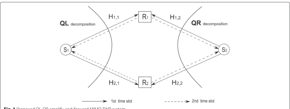
We consider a TWRC consisting of two source nodes,S1 andS2, and two relay nodes,R1andR2, as shown in Fig. 1.
The source and relay nodes are equipped withMandN
antennas, respectively. We adopt the relay protocol with two time slots introduced in [14]. In the first time slot, the information vectorxi ∈ CG×1, whereG ≤ M, is linearly processed by a precoding matrix,Vi ∈ CM×M, and then transmitted to the relay nodes. In this paper, we assume that each transmit antenna satisfies the unity transmission power constraint, which is trxixHi = IM. The received signals atRi,i∈ {1, 2}can be expressed as
yR1 =H1,1s1+H1,2s2+nR1
yR2 =H2,1s1+H2,2s2+nR2, (1)
whereyRi ∈CN×1,i∈ {1, 2}, indicates the received signal vector, Hi,j ∈ CN×M,i,j ∈ {1, 2}, represents the chan-nel matrix from source j to relay i, as shown in Fig. 1,
si = Vixi ∈ CM×1 is the transmitted symbol vector
fromSi with a power constraint trEsisHi ≤ Pi, and nRi ∼CN
0,σRi2IN
represents the additive white Gaus-sian noise (AWGN) vector with zero mean and variance σ2
Riat relay nodei.
In the second time slot, the relay node Ri linearly
amplifies yRi with anN ×N matrixFi and then
broad-casts the amplified signal vector xRi to source nodes 1 and 2. The signal transmitted from relay nodei can be expressed as
Fig. 1Proposed QL-QR amplify-and-forward MIMO TWR system
Using (1) and (2), the received signal vectors atS1and
S2can be, respectively, written as
y1=HT1,1F1H1,1s1+HT1,1F1H1,2s2+HT2,1F2H2,1s1
+ HT2,1F2H2,2s2+HT1,1F1nR1,+HT2,1F2nR2+n1 y2=HT1,2F1H1,1s1+HT1,2F1H1,1s2+HT2,2F2H2,1s1
+ HT2,2F2H2,1s2+HT1,2F1nR1+HT2,2F2nR2+n2. (3)
whereHTi,j,i,j∈ {1, 2}, indicates theM×Nchannel matrix from the relay nodeito the source nodejandni,i∈ {1, 2}, is anM×1 noise vector atSi.
We assume that the relay nodes perfectly know the channel state information (CSI) ofHi,j. The relay nodeRi performs the optimizations ofFi andViand then trans-mits the information to the source nodes 1 and 2. Since
source node i knows its own transmitted signal vector
si and full CSI, the self-interference components in (3) can be efficiently canceled. The effective received signal vectors are given by
y1 = HT1,1F1H1,2s2+H2,1T F2H2,2s2+HT1,1F1nR1
+HT2,1F2nR2 +n1
= H1s2+n1, (4)
y2 = HT1,2F1H1,1s1+HT2,2F2H2,1s1+HT1,2F1nR1
+HT2,2F2nR2 +n2
= H2s1+n2, (5)
where H1 = HT1,1F1H1,2+HT2,1F2H2,2 andH2 = HT1,2
F1H1,1+HT2,2F2H2,1 are the equivalent MIMO channels seen at source nodesS1andS2, respectively. The vectors
n1=HT1,1F1nR1+HT2,1F2nR2+n1andn2=HT1,2F1nR1+ HT2,2F2nR2 +n2are the equivalent noises at source nodes S1andS2, respectively.
Due to the lower computational complexity, linear receivers are applied at source nodeito retrieve the trans-mitted signals sent from the other nodes. The estimated signal waveform vector is given assi = WHiyi, whereWi is anM×Mweight matrix, withi=2 fori=1 andi=1 fori=2. From (4), the MSE matrix of the signal waveform estimation is denoted byMSEi = E(si−si) (si−si)H
, which can be further written as
MSEi =
WHi Hi−IM WHi Hi−IM H
+WHi CniWi (6)
whereCni=HTi,iFiFHi H∗i,i+HTi,iFiFiHH∗i,i+IMis the equiv-alent noise covariance. The sum-MSE of the two source nodes in the proposed system model can be written as
MSEsum=MSE1+MSE2. (7)
Note that the sum-MSE minimization criterion mea-sures the overall transmission performance of both the DL and the UL. Since the two data streams are transmitted at different directions during the two time slots,MSEsumis considered in the TWR network.
3 Joint source and relay beamforming design In this section, we develop an iterative QL-QR algorithm by using the MSE balancing result. The QL-QR algo-rithm involves two steps, i.e., the linear receiver matrix optimization and the joint source and relay beamformer design.
3.1 Proposed optimal detector and optimization problem
We would like to find the jointly optimal beamforming vectorsWi,Vi, andFisuch that the following sum-MSE is minimized:
min Wi,Fi,Vi
According to (2), we consider the following individual transmission power constraint at relay node:
trFiDiFHi
≤PRi, (9)
where Di = Hi,iViVHi HHi,i +Hi,iViVHi HHi,i +IN and the PRi denotes the individual power constraint at the relay nodeRi. The transmission power constraint at two source nodes can be written as
trViVHi ≤Pi, i=1, 2 (10)
where Pi is the available power at theith source node. According to (8), (9), and (10), the joint optimization problem of the sum-MSE can be formulated as follows:
min
Wi,Fi,Vi MSEsum
s.t. trFiDiFHi
≤PRi, tr
ViVHi
≤Pi. (11)
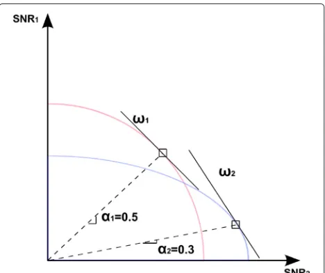
It is shown in [20] that at the optimum, SNR1 = SNR2 holds true, thus leading to an SNR balancing result. Oth-erwise, if SNR1>SNR2, thenP2can be reduced to retain SNR1 = SNR2, and this reduction ofP2will not violate the power constraint, i.e.,
P1·SNR1=P2·SNR2. (12)
In Fig. 2, we show two examples of the SNR regions with α1=0.5 andα2=0.3, whereωi∈[0, 1] is a Lagrange mul-tiplier weight value andαi∈[0, 1] is an SNR weight value. We have assumed that the sum of SNR is a constant value. It is clear that the SNR region ofα1is larger than that of α2. For further details, see [20]. As discussed in [21], the optimization problems have the performance matrix that
Fig. 2Examples of the SNR regions achieved in a TWRC with two relays
are functions of SNR , namely the MSE at the output of a linear-MMSE (LMMSE) filter of each user:
MSE= 1
1+SNR. (13)
By these two approaches, the max-min optimization problem in (11) can be efficiently written as
min W1,Fi,V2
MSE1 (14)
s.t. trFiDiFHi
≤PRi, MSE1=MSE2,∀i=1, 2. (15)
Since the optimization problem (14)–(15) is nonconvex, it is difficult to obtain the globally optimal solution. In this paper, we present a locally optimal solution of the joint optimization problem overWi,Vi, andFi, wherei=1, 2, which can be solved by three stages, i.e., (1) the linear receiver weighted matrices are optimized with the fixed source precoding matrix Vi and relay amplifying matri-ces Fi (Wi is not in constraint (15)). (2) With givenWi and fixedFi, updateVi. (3) With givenWiandVi, obtain suboptimalFito solve (14).
Lemma 1.For any fixed Vi andFi, the minimization problems in (14) are convex quadratic problems and the optimalWican be obtained as the Wiener filter [22] which is used to decodesishown as follows:
Woi =HiHiH+Cni−1Hi, (16)
Proof. For source node i, the MSE can be further expressed as
MSEi = WHi HiHHi Wi−WHi Hi−HHi Wi
+IM+WHi CniWi (17)
Based on (17), the derivation of an optimal MSE detec-tion matrix Wopti is equivalent to solving the following equation [23]:
∂MSEi
∂WHi =2HiH
H
i Wi−2Hi+2CniWi=0. (18)
Then, we may obtain the closed-form solution ofWi, which is
Woi =HiHiH+Cni−1Hi. (19)
This completes the proof.
With the optimal Wo1 fixed, the outer minimization problem in (14) can be rewritten as
min F1,F2,V1,V2
MSEo1
s.t. trFiDiFHi
whereMSEoi is the MSE matrix usingWoi. By substituting (16) into (6), we have
MSE1o=IM+HH1C−n11H1−1, i=1, 2. (21)
Note that the matrix inversion lemma is used to obtain (21).
3.2 Joint optimal source and relay beamforming matrices design and iterative algorithm
In this section, we focus on the source and relay beam-forming matrices design and develop an iterative algo-rithm which is suboptimal for the general case but has a much lower computational complexity. For the fixedFi, the source precoding matrixViis optimized by solving the following problem:
The Lagrangian function associated with the problem (22) is given by
whereμi≥0 is the Lagrange multiplier.
Case 1: Whenμi =0, making the derivative ofLVwith respect toVibe zero, we obtain
∂LV
SinceVi andi are nonsingular matrices, (24) can be represented as
IM+VHi iVi=0. (25)
Simplifying (25), IM > 0 and VHi iVi ≥ 0. Conse-quently, inCase 1, the optimal solution is not existent.
Case 2: When μi > 0, we rewrite the Lagrangian
Since VHi and i are nonsingular matrices, multiply
both sides byVH
Sinceiis Hermitian and positive definite, we apply the
Choleskey decomposition ofi = Hi i, where i is a
lower triangular matrix. Consequently, we represent (28) as
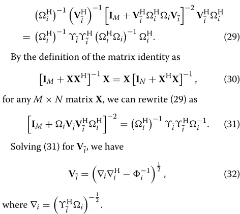
By the definition of the matrix identity as
Figure 3 shows our proposed relay filter design, which forwards the received signal (input) fromS1amplified by a left filter (LF) matrixFL,iand the signal fromS2 ampli-fied by a right filter (RF) matrixFR,ito a center filter (CF) FD,i.FD,iamplifies the outputs from the LF matrixFL,iand the RF matrixFR,i (i ∈ {1, 2}denotes relay node i) and forwards them toS1andS2(output).1
Lemma 2.The optimal relay filter constructive ofFL,FR, ces which relate to QL and QR decompositions for the dependent channel coefficients. computational complexity will be considerably increased compared withCase a, so we exclude it.
ForCase a, Before we develop a numerical method to solve vectorFD,i, let us have some insights into the struc-ture of this suboptimal relay beamforming matrix. To simplify relay beamforming matrixFD,i, we introduce the following properties:
Property 1: The statistical behavior of a unitary matrix
U remains unchanged when multiplied by any unitary
matrixTindependent ofU. In other words,TUhas the same distribution asU, i.e., in (33),
|F1| = |FL,1FD,1FR,1| = |FD,1|
|F2| = |FL,2FD,2FR,2| = |FD,2|. (37)
Now, let us introduce the followingQLdecomposition:
Similarly, let us introduce another decomposition,
namelyQRdecomposition, as tuting (38) and (39) back into (4), we can get equivalent received signals shown as obtained from the covariance ofCi, we have
Ci = ninHi
= LTiFD,iFHD,iLi∗+LTiFD,iFHD,iL ∗
i +IN. (41)
For fixed Vi, using (40) and Property 1, the optimal problem (20) becomes
where we have employed the principle min(a) = max
(a−1), fora=0. By using the lemma tr(A+B)=tr(A)+ tr(B), (42) can be represented as
trHHi C−i1Hi
+n. (44)
Since the matrix Ci is Hermitian and positive defi-nite, we can decompose this matrix using the Cholesky factorization as
Ci = Hi i (45)
where=a denotesnhas nothing to do with the maximum solution andBi = HHi −i 1. Therefore, the optimal prob-lem can be represented as the determinant maximization ofB2i [29].
In Case a, since FD,i is the block diagonal matrix, its determinant can be written as
detFD,i=detFD,i,1·detFD,i,2. (47) is an N4 × N4 diagonal matrix. Substituting (49) back into BA−1D, we have D, andA, respectively. To simplify our discussion, we assume thatFD,i,iis a semi-positive matrix; thus, we have the minimum solution asbidi = 0. Interestingly, if both bianddiare 0,FD,i,iis a diagonal matrix. Otherwise, it is a lower/upper triangular matrix. In addition, forS1, the equivalent channelH1, since the termsLT1,LT2,R1, andR2 are upper triangular matrices, the optimalFD,ishould be an upper triangular matrix. Since the equivalent channel H2,L1,L2,RT1, andRT2 are lower triangular matrices for
S2, the optimal FD,i is a lower triangular matrix. There-fore, if and only ifFD,iis a diagonal matrix, the sum-MSE is optimal in our proposed method.
This completes the proof forLemma 2.
Property 2: For anyM×Nrectangular matricesGand J, matricesAandBare lower/upper triangular matrices based on QR or QL decomposition ofGandJ. Ifai,i+bi,i= 0, whereai,i andbi,i are diagonal elements of matricesA andB, respectively, we can easily obtain
det(A+B)=
i are also lower triangular matrices, we have
detBi = detHHi det−i 1
After introducing slack the variable τi, the objective problem can be equivalently converted into the opti-mization one with respect to an individual relay power constraint, shown as follows: dent on the beamformerFD,tand with respect to (55) and (56). Thus, by using (53), we have
τi≤ line the iterative beamforming design algorithm as follows (QL−QR Algorithm):
Clearly, Algorithm 1 will converge to a sub-optimal solution asτmax(n) −τmax(n−1) ≤ . Therefore, is initialized to be a small value andNmaxis set to limit the number of iterations.
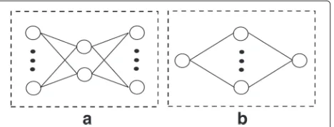
Fig. 4The extended system model.aTheKpairs of the source node scenario.bTheTrelay node scenario
another, we can design each relay node comprised ofK
RFs, LFs, and one CF. Therefore, the extended system model (a) can be classified as another version of our pro-posed system model withKparallel nodes. The objective problem can be expressed as
max the sum-MSE of the multi-pair scenario. It is clear that (58) is a bi-convex problem which is similar to (54)–(56) with different effective channel coefficients and can be solved by our proposed algorithm.
Algorithm 1QL-QR Algorithm
In Fig. 1b, a TWRC consisting of two source nodes and
Lrelay nodes is considered. Obviously, by employing the MSE balancing result, the objective of the extended sys-tem model (b) is to minimize the sum-MSE, which is subject to the individual relay transmit power constraint, shown as relay node, the objective problem (59) is non-convex. In this scenario, we consider a two-stage solution where in the first step, the semi-infinite constraints are converted to linear matrix inequalities (LMI) and in the second step, we use our proposed iterative algorithm to solve it. By using the S-Lemma [28], the relay power constraint can be converted into the LMI version, we have
⎡
where vec(·)denotes to stack the columns of a matrix into a single vector. Now, the objective problem (59) becomes
min
In step 2, we use an iterative algorithm based on alter-nating convex search (ACS) to solve the resulting convex problem. The algorithm is almost the same as our pro-posed one which only converts [Algorithm 1, Steps 4–11] into “for fixedW(in),Vi(n)updateF(in)via solving (61)”.
4 Computational complexity analysis
Table 1Computational complexity of the proposed QL-QR algorithm
Step Operations FLOPS Case:(2, 2, 2)×6
1 V1,V2 2×K40N3i −24N2i +17Ni 1560
2 QL,1L1,QL,2L2 2×16KN2TNi−NTN2i +13N3i
4864
3 QR,1R1,QR,2R2 2×16K
N2
TNi−NTN2i +13N3i
4864
4 HT1,1F1H1,2 8N2TNi+4NTN2i +2NTNi 696
5 HT2,1F2H2,2 8N2TNi+4NTN2i +2NTNi 696
6 C1 2K
32N2TNi+8NTNi+2N2T−4Ni+3NT
14,856
7 Hii−1 K143N3T−2N2T+NT
2826
8 detB2
1 4K
N3T+N2T+2NT 3168
Total 33,530
times its real computation. According to [31], the required number of FLOPs of each matrix is described as follows:
1. Multiplication ofm×nandn×pcomplex matrices:
8mnp−2mp;
2. Multiplication ofm×nandn×mcomplex
matrices:4nm×(m+1);
3. SVD of anm×n(m≤n)complex matrix where only
is obtained:32(mn2−n3/3);
4. SVD of anm×n(m≤n)complex matrix where only
andare obtained:32(nm2+2m3);
5. SVD of anm×n(m≤n)complex matrix whereU,
, andare obtained:8(4n2m+8nm2+9m3);
6. Inversion of anm×mreal matrix using
Gauss-Jordan elimination:2m3−2m2+m;
7. Cholesky factorization of anm×mcomplex matrix:
8m3/3;
8. QR or QL decomposition of anm×nconplex matrix
16n2m−nm2+13m3.
For the RBD method [32], the authors consider a lin-ear MU-MIMO precoding scheme for DL MIMO sys-tems. For the non-regenerative MIMO relay systems [33], the authors investigate a precoding design for a three-node MIMO relay network. In [2], a relay-aided sys-tem based on a quasi-EVD channel is proposed. We
compare the required number of FOLPs of our proposed method with conventional precoding algorithms, such as the RBD, the non-regenerative MIMO relay system, and the CD-BD algorithm as shown in Tables 1, 2, 3, and 4,
respectively, under the assumption that NT = NR and
Ni=NT−Ni.
For instance, the (2, 2, 2) × 6 case denotes a system with three users (K = 3), where each user is equipped
with two antennas (Ni = 2) and the total number of
transmit antennas is six (NT = 2 × 3 = 6). The
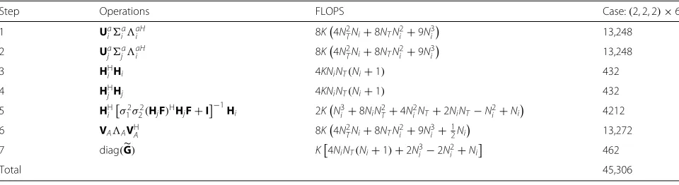
required number of FLOPs of the QL-QR algorithm, the RBD, the non-regenerative MIMO relay system, and the CD-BD algorithm are counted as 33,530, 40,824, 45,306, and 34,638, respectively. From these results, we can see that the reduction in the number of FLOPs of our proposed precoding method is 17.87, 25.99, and 3.20 % on an individual basis compared to the RBD, the non-regenerative MIMO relay systems, and the CD-BD algorithm. Thus, our proposed QL-QR algorithm exhibits lower complexity than conventional algorithms. In addi-tion, the complexity reduces asNi andNT increase with fixedK.
We summarize our calculation results of the required number of FLOPs of the alternative methods in Tables 1, 2, 3, and 4 and show them in Figs. 5 and 6. Figure 5 shows
Table 2Computational complexity of the non-regenerative MIMO relay system [33]
Step Operations FLOPS Case:(2, 2, 2)×6
1 Ua
iiaaHi 8K
4N2
TNi+8NTN2i +9N3i
13,248
2 Ua
jjaaHi 8K
4N2
TNi+8NTN2i +9N3i
13,248
3 HH
iHi 4KNiNT(Ni+1) 432
4 HH
jHj 4KNiNT(Ni+1) 432
5 HH
i
σ2
1σ22(HjF)HHjF+I−1Hi 2KN3i +8NiN2T+4N2iNT+2NiNT−N2i +Ni 4212
6 VAAVHA 8K
4N2
TNi+8NTN2i +9N3i +12Ni 13,272
7 diag(G) K4NiNT(Ni+1)+2N3i −2N2i +Ni 462
Table 3Computational complexity of the conventional RBD [32]
Step Operations FLOPS Case:(2, 2, 2)×6
1 Ua
iiaaHi 32K(NTN2i +2N
3
i) 21,504
2 iaTia+ρ2I−1/2 K18NTNi2−2N2i
336
3 Va
iDai 8KN3T 5184
4 HiPai K
8NTN2i −2N2i
552
5 UbiibVbHi 64K98Ni3+NTN2i +12N2TNi 13,248
Total 40,824
the computational complexity whereNi = 2 and a value
of K varies. And Fig. 6 shows the computational
com-plexity where K = 4 and a value of Ni varies. For the RBD method, the orthogonal complementary vectorVk,0 requiresKtimes SVD operations. If onlyVk,0is obtained, it is not computationally efficient. In step 5, the efficient channelHeff = HiPai is decomposed by the SVD with a dimension Reff ×NT, whereReff is the rank of Heff. In the non-regenerative MIMO relay method and the CD-BD algorithm, two SVD operations are performed for the channels from the source to the relay and from the relay to the destination, and then the efficient channel covariance matrix is measured. In the non-regenerative MIMO relay
method, the authors computeAusing the EVD, and then
they diagonalizeG. In the CD-BD algorithm, the authors calculateVai by the SVD ofH†mse, and then they structure Vbi by using the Choleskey decomposition.
In our proposed QL-QR algorithm, we take advantage of QL and QR decompositions instead of the SVD oper-ation, and then we compute an efficient channel as well as decompose a noise covariance matrix by the Choleskey decomposition. Finally, we calculate the determinant of B2i to solve an optimization problem. Obviously, our pro-posed QL-QR algorithm outperforms conventional algo-rithms in the light of the computational complexity.
5 Simulation results
In this section, we study the performance of the proposed QL-QR algorithm for two-way MIMO relay networks. All the simulations are performed on the assumption
that all the channel estimates are the Rayleigh fading channels, and they are independent and identically dis-tributed (i.i.d.) complex Gaussian random variables. The noise variancesσi2are equally given asσ2. All the simula-tion results are averaged over 1000 channel trials.
In Fig. 7, we compare the sum mutual information (SMI) of various MU-MIMO schemes where full CSI is known at each node. We setP1=P2=10 dB andM=1 with an equal power budget for the two relays. The negative SMI is adopted in [16] which can be defined as
MIsum=log2|MSE1| +log2|MSE2|. (62)
In our proposed method, the SMI shown in the simula-tion results is calculated as−2 log2|B2i|by using (45), (52), and (53). It can be observed that the proposed QL-QR algorithm has the same SMI performance as an optimal solution in [16].
Figure 8 shows the performance of our proposed SMI performance versus the number of the relays,T, which is even. We consider a practical scenario with different relay power constraints and setPR =30 dB. It is clear that, for different values ofP1andP2, a solution of our proposed QL-QR algorithm shows better performance than a max-power solution.
Figure 9a, b exhibits the BER performance of the BD water filling, the RBD, the SVD-RBD, and our proposed QL-QR method, where the quadrature phase shift keying (QPSK) and 16 quadrature amplitude modulation
(16-QAM) are made use of. As pointed out in [35], the
Table 4Computational complexity of the CD-BD algorithm [2]
Step Operations FLOPS Case:(2, 2, 2)×6
1 UH
i,1i,1i,1 8K(4N2TNi+8NTN2i +9N3i) 13,248
2 H
i,2i,2Ui,2 8K4NT2Ni+8NTN2i+9N3i
13,248
3 Hi,2WHi,1 K8NiN2T−2NiNT+4NiNT×(Ni+1) 2088
4 LH
iLi 2KNi+2NTNi×(Ni+1)+4N3i/3
508
5 H†mse 4N3
R/3+12N2RNT−2N2R−2NTNR 2736
6 Hi,iVaiVbi 8K
4NTN2i −4N3i/3+N2i(Ni+1) 2336
7 QiQHi +σi2i−1 K4NRNi×(Ni+1)+3Ni+2N3i −2N2i
474
Fig. 5The complexity comparisons for required FLOPs versus the number of the usersK
BER performance for a MIMO precoding system is actu-ally determined by the energy of the transmitted signal.
To simplify our discussion, we assume a = 0. In the
RBD, detHHH = $mi=1λ2i, where H ∈ CN×M, for
M < N, is an equivalent channel matrix with its
eigen-values λi. In our proposed QL-QR method, for source
nodeS1, we have det H1HH1
=$m
i=1ς12. Under the stip-ulation that detFD,i = 1, we are able to easily obtain
λi = ςi. Therefore, our proposed QL-QR method has
the same BER performance as that of the SVD-RBD method.
Fig. 6The complexity comparisons for required FLOPs versus the number of the receive antennasNifor each user
Fig. 7The achieved SMI forN=4, 2
6 Conclusions
This paper studies a joint optimization problem of an AF based on the MIMO TWRC, where two source nodes exchange their messages with two relay nodes. A relay filter is designed, which is able to efficiently join the source and the relay nodes. Our main contribution is that the optimal beamforming vectors can efficiently be computed using determinant maximization techniques through an iterative QL-QR algorithm based on a MSE balancing method. Our proposed QL-QR algorithm can significantly reduce the computational complexity and has an equivalent BER performance to that of the SVD-BD algorithm.
Fig. 9 aBER performance on the Rayleigh fading channel with QPSK. bBER performance on the Rayleigh fading channel with 16-QAM
Endnote
1For example: ForS
1, the equivalent channel can be written asH1=HT1,1F1H1,2+HT2,1F2H2,2=
HT1,1FL,1FD,1FR,1H1,2+HT2,1FL,2FD,2FR,2H2,2. ForS2, the equivalent channel can be written as
H2=HT1,2F1H1,1+HT2,2F2H2,1=
HT1,2FR,1FD,1FL,1H1,1+HT2,1FR,2FD,2FL,2H2,2.
Competing interests
The authors declare that they have no competing interests.
Acknowledgements
This work was supported by MEST 2015R1A2A1A05000977, NRF, South Korea, National Nature Science Foundation of China (61201249, 61359153, 61272495), the Brain Korea 21 PLUS Project, National Research Foundation of Korea, DHU Distinguished Young Professor Program (15D210402), Natural Science Foundation of Guangdong Province (S2011040004068), China, and the scientific research foundation for returned overseas Chinese Scholars, State Education Ministry.
Author details
1Division of Electronic and Information Engineering, Chonbuk National
University, Jeonju-si, South Korea.2School of Information Science and Technology, Donghua University, Shanghai, China.3School of Information
Science and Engineering, Central South University, Changsha, China.4School of Mechanical and Electrical Engineering, Guangzhou University, Guangzhou, China.
Received: 15 February 2015 Accepted: 1 November 2015
References
1. JN Laneman, DNC Tse, GW Wornell, Cooperative diversity in wireless networks: efficient protocols and outage behavior. IEEE Trans. Inf. Theory.
50(12), 3062–3080 (2004)
2. W Duan, W Song, SS Song, MH Lee, Precoding method interference management for quasi-EVD channel. Sci. World J.2014(2014). Article ID 678578
3. TM Cover, AAE Gamal, Capacity theorems for the relay channel. IEEE Trans. Inf. Theory.25(5), 572–584 (1979)
4. Z Zhao, M Peng, Z Ding, W Wang, H-H Chen, Denoise-and-forward network coding for two-way relay MIMO systems. IEEE Trans. Veh. Technol.63(2), 775–788 (2014)
5. S Simoens, O Munoz-Medina, J Vidal, Coso AD, Compress-and-forward cooperative MIMO relaying with full channel state information. IEEE Trans. Signal Pross.58(2), 781–791 (2010)
6. B Rankov, A Wittneben, Spectral efficient protocols for half-duplex fading relay channels. IEEE J. Sel. Areas Commun.25(2), 379–389 (2007) 7. T Koike-Akino, P Popovski, V Tarokh, Optimized constellations for two-way
wireless relaying with physical network coding. IEEE J. Sel. Areas Commun.27(5), 773–787 (2009)
8. S Xu, Y Hua, Optimal design of spatial source-and-relay matrices for a non-regenerative two-way MIMO relay system. IEEE Trans. Wireless Commun.5(10), 1645–1655 (2011)
9. Y Rong, Joint source and relay optimization for two-way linear nonregenerative MIMO relay communications. IEEE Trans. Signal Process.
60(12), 6533–6546 (2012)
10. K-J Lee, H Sung, E Park, I Lee, Joint optimization for one and two-way MIMO AF multiple-relay systems. IEEE Trans. Wireless Commun.9(12), 3671–3681 (2010)
11. H Bolcskei, RU Nabar, O Oyman, AJ Paulraj, Capacity scaling laws in MIMO relay networks. IEEE Trans. Wireless Commun.5(6), 1433–1444 (2006) 12. K-J Lee, KW Lee, H Sung, I Lzee, inProc. IEEE Veh. Technol. Conf.Sum-rate
maximization for two-way MIMO amplify-and-forward relaying systems (Barcelona, Spain, 2009), pp. 1–5
13. F Roemer, M Haardt, Algebraic norm-maximizing (ANOMAX) transmit strategy for two-way relaying with MIMO amplify and forward relays. IEEE Signal Process. Lett.16(10), 909–912 (2009)
14. T Unger, A Klein, Duplex schemes in multiple antenna two-hop relaying. EURASIP J. Adv. Signal Process.2008(2008). Article ID 128592 15. N Jindal, Z Luo, inProceedings of the IEEE International Symposium on
Information Theory (ISIT 06). Capacity limits of multiple antenna multicast (Seattle, WA, USA, 2006), pp. 1841–1845
16. R Zhang, Y-C Liang, CC Chai, S Cui, Optimal beamforming for two-way multi-antenna relay channel with analogue network coding. IEEE J. Selected Areas Commun.27(5), 699–712 (2009)
17. R Wang, M Tao, Joint source and relay precoding designs for MIMO two-way relaying based on MSE criterion. IEEE. Trans. Signal Process.
60(3), 1352–1365 (2012)
18. H Wang, L Li, L Song, X Gao, A linear precoding scheme for downlink multiuser MIMO precoding systems. IEEE Commun. Lett.15(6), 653–655 (2011)
19. H Park, HJ Yang, J Chun, R Adve, A closed-form power allocation and signal alignment for a diagonalized MIMO two-way relay channel with linear receivers. IEEE Trans. Signal Process.60(11), 5948–5962 (2012) 20. V Havary-Nassab, S Shahbazpanahi, A Grami, Optimal distributed
beamforming for two-way relay networks. IEEE Trans. Signal Process.
58(3), 1238–1250 (2010)
21. P Viswanath, V Anantharam, DNC Tse, Optimal sequences, power control, (1999) and user capacity of synchronous CDMA systems with linear MMSE multiuser receivers. IEEE Trans. Inf. Theory.45(6), 1968–1983 22. SM Kay,Fundamentals of Statistical Signal Processing: Estimation Theory.
(Prentice Hall, Englewood Cilffs, NJ, 1993)
23. DC Lay,Linear Algebra and Its Applications, 4th edition. (University of Maryland Press, College Park, USA, 2012)
24. R Zhang, Y-C Liang, CC Chai, Cui S, Optimal beamforming for two-way multi-antenna relay channel with analogue network coding. IEEE J. Sel. Areas Commun.27(5), 699–712 (2009)
25. C Lameiro, J Va, I Santamara, Amplify-and-forward strategies in the two-way relay channel with analog Tx–Rx beamforming. IEEE Trans. Veh. Technol.62(2), 642–654 (2013)
26. Y Rong, Simplified Algorithms for optimizing multiuser multi-hop MIMO relay systems. IEEE Trans. Commun.59(10), 2896–2904 (2011) 27. S Boyd, L Vandenberghe,Convex Optimization. (Cambridge Univ. Press,
Cambridge, UK, 2004)
28. Y Huang, D Palomar, S Zhang, Lorentz-positive maps and quadratic matrix inequalities with applications to robust MISO transmit beamforming. IEEE Trans. Signal Process.61(5), 1121–1130 (2013) 29. A Benavoli, L Chisci, A Farina, Estimation of constrained parameters with
30. X Gao, L Li, P Zhang, L Song, G Zhang, Q Wang, H Tian, Low-complexity RBD precoding method for downlink of multi-user MIMO system. Electronics Lett.46(23), 1574–1576 (2010)
31. GH Golub, CF Van Loan,Matrix Computations, Johns Hopkins Studies in the Mathematical Sciences, 3rd edition. (Johns Hopkins University Press, Baltimore, Md, USA, 1996)
32. H Wang, L Li, L Song, X Gao, A linear precoding scheme for downlink multiuser MIMO precoding systems. IEEE Commun. Lett.15(6), 653–655 (2011)
33. R Mo, YH Chew, Precoder design for non-regenerative MIMO relay systems. IEEE Trans. Wireless Commun.8(10), 5041–5049 (2009) 34. S Vishwanath, N Jindal, A Goldsmith, inProceedings of the International
Conference on Communications (ICC 02). On the capacity of multiple input multiple output broadcast channels (NY, USA, 2002), pp. 1444–1450 35. CB Peel, BM Hochwald, AL Swindlehurst, A vector-perturbation technique
for near capacity multiantenna multiuser communication—part I: channel inversion and regularization. IEEE Trans. Commun.52(1), 195–202 (2005)
Submit your manuscript to a
journal and benefi t from:
7Convenient online submission 7Rigorous peer review
7Immediate publication on acceptance 7Open access: articles freely available online 7High visibility within the fi eld
7Retaining the copyright to your article
![Table 3 Computational complexity of the conventional RBD [32]](https://thumb-us.123doks.com/thumbv2/123dok_us/944448.1115158/10.595.56.540.602.734/table-computational-complexity-conventional-rbd.webp)


