Design and Construction of Linear Buck
Converter Using Lm317 with Variable Input
and Constant Output Voltage
Adithya Ballaji1, Akshith Monnappa K2
P.G. Student, Department of Electrical and Electronics Engineering, Reva University, Bangalore, Karnataka, India1, 2
ABSTRACT: A versatile operation of any electronic circuitry depends on the power source supplying the power for its operation. The use of DC linear regulators is dated several years back in the history, these regulators are used by designers for various projects and other applications.
In this paper, design of a variable input and constant output voltage DC-DC linear buck converter for an input voltage varying between 3V-40V and a constant output voltage of 5V DC power supply is discussed. The buck converter is implemented using an integrated circuit(IC), LM317. The constructed buck converter was tested for load and line regulation cited in the datasheets for stability. The test and analysis for the linear buck converter was done using simulation and hardware setup. The output measurements indicate that the power supply is functional. The measured output values match the simulation results of the test circuit.
The developed output power supply unit is important in measurements, laboratories and test setups. It is implemented for all general applications that require power supply unit
.
KEYWORDS: Linear Buck Converter, LM317, Power Supply Unit.
I. INTRODUCTION
The rapid progression in the technology has a major influence on all electrical and electronic gadgets. The developments of novel devices that are compact are in demand. These usually require low power AC or DC sources for their operation. The operation of any electrical and electronic circuitry mainly depends on the power supply unit. The power supply unit is a fundamental part in any electrical or electronic device that supplies a constant or a variable voltage for its operation.
Generally, a basic power supply unit without a regulator produces rippled output, whereas one with a regulator produces a ripple-free output. The power supply unit with a regulator is referred to as a regulated power supply. Due to the advancement in the field of electronics, the need for a DC power supply unit is evident where in which the linear buck converter can be used with constant DC output voltage over an wide range variable input voltage.
II. RELATEDWORK
With the day to day rise in technological evolution at its zenith, the emergence of new nanoscopic and microscopic electrical and electronic products continue to ensue and these products require DC source for their operation. Most of the existing power supply devices with various levels of complexities and sophistication has grasped the interest of researcher’s and thus over the time has led many researcher to publish their work on power supply units.
A stabilized variable power supply unit with a voltage range of 0.20v – 15.85v and current range of 0 – 3 Amps (45W) with a very low output impedance of 0.008 ohms has been developed and constructed in [1]. The study of regulation characteristics of a constructed power supply units to a certain load and line regulation has also been presented. The drawbacks of the circuit being the complexity of the circuit and the number of components are more with the addition of bridge rectifier circuit the losses tend to increase.
Linear power supply unit have problems with efficiency and to increase and solve this problem a custom-made bipolar linear power supply with homemade pre-regulator circuitry is in series in front of power stage. Thus with constant VDS
controlled pre-regulator, the power consumption can be reduced and efficiency can be increased which is presented in [2]. Even though the circuit is able to reduce the power consumption and increase the efficiency the complex circuit and operation is a drawback.
A transformer-based and transformer less-based changing controlled DC power supply along with the marketplace analysis and investigation involving the proposed project and their own aspects of uses. The product quality, expense, dimension, excess weight, efficiency as well as effective manufacturing regarding DC power supply has been showcased in [3]. The transformer based carries more resultant current with providing the required isolation where as the transformer less provides a compact design.
Low voltage high current DC to DC power supply for 48V input is discussed in [4]. A single switch forward converter is used here. Secondary side rectification is done through synchronous rectifiers. Voltage conversion ratio of the converter is high. Using a transformer based topology is better for having high converter ratio. Here a new bifurcated transformer winding arrangement is proposed in this thesis. Here in [5] a highly efficiency Power Supply Unit for server power supply is presented. And to reduce the power conversion loss, power factor Collection circuit was designed into Bridgeless PFC using two switching components with 2 SiC diodes, and synchronous rectifier switching method was applied.
A comparative study of switching, integrated and linear regulator has been done in [6]. Synchronous converter offers very high efficiency and board space compared to linear circuit. In case of low cost design a discrete linear will be helpful, but the performance is effected with potential penalties, which lead additional features like heat sinks and protection devices.
A DC linear power supply unit with adjustable voltage is developed in [7]. The existing drawbacks of DC linear power supply are analysed and low cost, and ripple free power supply unit is developed.
The review of power supply technology based on the past, present and future is described in [8]. Here all the possible technology on power supply unit is presented with an idea of future internet technology and aggressive sustainable growth in the field of power supply is broadly discussed. Design and implementation a switching mode bipolar power stage of the correction power supply is presented in [9]. Here a switching type of power supply is used to produce and replace the power source for the original correction power supply. An overview of nuclear energy and power supply units for deep space and planetary science missions is showcased in [10]. The power supply unit is developed here for the purpose of deep space and planetary missions for space shuttles.
III.LINEARBUCKCONVERTER
The LM317 is a tuneable three-terminal voltage regulator with can provide more than 1.5Amps and an output voltage of 1.25 V to 37 V. represented in above figure 5.3.It requires only two external resistors for the output voltage. It has a line regulation of 0.01% and load regulation of 0.1%. Thus also includes a current limiting, thermal overload protection, and a safe operating area protection. Overload protection is functional even though adjust terminal is disconnected.
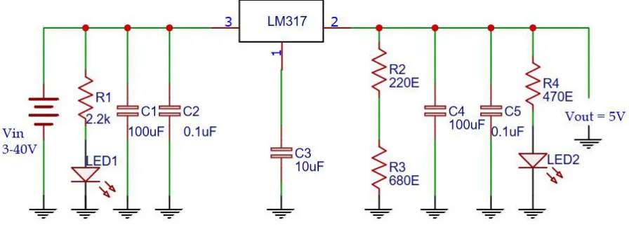
Here a linear buck converter is designed and developed using the LM317 voltage regulator with a variable input voltage of 3-40V and constant output voltage of 5V. The produced output voltage is constant with very less ripple and the output voltage is always less than the input voltage. Even if the adjusting terminal is removed the overload protection remains. The below Figure 1 shows circuit diagram of linear buck converter using LM317.
Fig 1: Circuit Diagram of linear buck converter
The above circuit consist of an LM317 three terminal voltage regulator with a variable input of 3-40V and a constant output of 5V. Here the LED’s are used for indication purpose of the input and output. The input capacitor is used as smoothing capacitor and as input filter to improve the power factor and also to remove unwanted and undesired frequency or noise. The output capacitors here are used for improving the transient responses of the system. The two external resistors R2 and R3 are enough to set the output voltage.
IV.DESIGNSPECIFICATIONS
The values for the ratio of the resistor are calculated using the formula mentioned below,
(1)
Since Iadj is less than 100uAmps the last term is neglected, thus setting the value of R2 to 220Ω, Vout to 5V and Vref to
1.25V, substituting in equation (1) we get R3equal to 680Ω. The designed values of the components are mentioned
below:-
V
input=3V to 40V
V
output= 5V
C
2= C
5= 0.1µF/50V (Ceramic)
R
1= 2.2K,1/4W,5%
R
2=220E,1/4W,5%
R
3=680E,1/4W,5%
R
5=470E,1/4W,5%
LED
1= Red, LED
2= Green
V. HARDWAREDESIGNAND EXPERIMENTALRESULTS
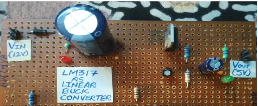
The linear buck converter using the LM317 was constructed on a general PCB board as shown in the Figure 2 below. As described in earlier section, the linear buck converter consists of a three terminal voltage regulator. As can be seen from the PCB designed circuit the input terminal has a diode connected to it for polarity check. There is input and output capacitors, the input capacitors are used as smoothing capacitor to suppress any noise in the signal and as a input filter to improve the power factor finally removing unwanted and undesired frequency or noise. Whereas the output capacitors are used to improve the transient responses of the system. The two external resistors R2 and R3 are enough to set the output voltage.
Fig 2: Linear buck converter using LM317 on general PCB
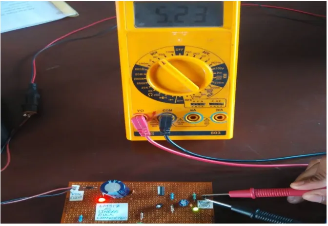
Fig 3: Experimental results of linear buck converter at 5V
From the above experimental setup it is clearly indicated the input power polarity is true, as the input red LED is blinking. And the output is high as the output green LED is blinking. By incorporating these LED for indication it helps during trouble shooting and makes it easy to fix the system issues. The below Figure 4 shows the simulation of linear buck converter in OrCAD Capture. Output for different input voltages have been run in the simulation and the output waveform is shown in the below Figure 5 for different values of input and output voltages.
Fig 4: Linear buck converter using LM317 Simulation using OrCAD Capture
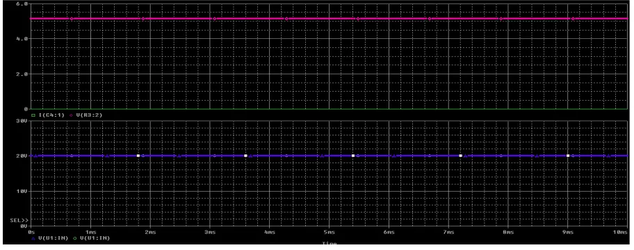
Fig 5: VIN = 10V and VOUT = 5V
The above waveform shows the input voltage to the linear buck converter of 10V and the output voltage of 5V constant without any transients and ripple.
Fig 6: VIN = 20V and VOUT = 5V
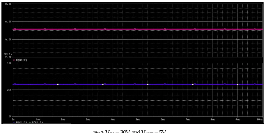
Fig 7: VIN = 30V and VOUT = 5V
The output for different values of input voltage is tabulated below in Table 1 with graph for the same values.
SL.NO INPUT VOLTAGE
(VIN)
OUTPUT VOLTAGE (VOUT) Simulation
OUTPUT VOLTAGE (Vout) Hardware
1 8V 5V 5.10V
2 10V 5V 5.23V
3 20V 5V 5.12V
4 25V 5V 5.25V
5 30V 5V 5.18V
Table. 1 Output Voltage (VOUT) comparison with Hardware results for different Input Values (VIN)
The Figure 8 below shows the comparison between the simulated values and Experimental values with different input voltages.
From the above Figure 8 it can be clearly seen that the designed linear buck converter output values during simulation and experimental setup are overlapping at more than once. The PCB design was carried out using Proteus 8 professional for finally developing the prototype into the product.
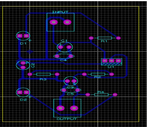
Fig 9: PCB Layout for Linear buck converter using LM317
The above Figure 9 Shows the PCB layout for the linear buck converter. The gerber view of the PCD design is shown in the Figure 10 below.
VI. CONCLUSION
A linear buck converter using LM317 has been designed and developed. The linear buck converter has a variable input of 3V-40V and constant output of 5V. The designed power supply unit has ripple-free output, line regulation of 0.01% and load regulation of 0.1%.
The device is simple to design and implement cost effective, compact and light weight as it uses very less components. It has less heat dissipation compared to other discrete devices. The linear buck converter type power supply unit is commonly used in applications like, test zig for defective component checking, HVAC, battery charging for mobile applications, research labs, Electroplating, television, communication transmissions and renewable energy applications.
REFERENCES
[1] Adelakun Adedayo Oke, Rabiu Jamiu.Ariyo, Egunjobi Abiodun Isiaka, Akinnubi Rufus Timotheu, “Design and construction of a stabilize variable power supply unit” Innovative Systems Design and Engineering ISSN 2222-1727 (Paper) ISSN 2222-2871 (Online)Vol.5, No.6, 2014 [2] Kuo-Bin Liu, Chen-Yao Liu and Jeng-Tzong Sheu, “High Efficiency Linear Power Supply with preregulator controlled by keeping constant RDS
of MOSFET” Proceedings of the 1999 Particle Accelerator Conference, New York, 1999
[3] Engr.Qazi Waqar Ali, Prof. M.Zahir Khan, “Simulation and Comparative Analysis of Linear DC Power Supply” Int. Journal of Engineering Research and Applications ISSN: 2248-9622, Vol. 3, Issue 6, Nov-Dec 2013, pp.1251-1256
[4] P. Hari Krishna Prasad and Dr. M. Venu Gopal Rao, “Design of efficient low voltage high current dc to dc power supply” International Journal of Engineering Research and Applications (IJERA) ISSN: 2248-9622 Vol. 2, Issue 2,Mar-Apr 2012, pp.1565-1570
[5] Jong- Mu Lee, Seung- Wook Hyun, Prof. Chung- Yuen Won, “High Efficiency Power Supply Unit For Server Power Application” International Conference on Electrical Machines and System (ICEMS) October 25-28 Pattaya City, Thailand.
[6] Rich Nowakowski, Robert Taylor, “Linear versus switching regulator in industrial application with a 24V Bus” Analog Applications Journal, 3Q, 2013.
[7] Guo Jian, Zhu Jie, Zhou Li, “Design of a DC Linear Power with Adjustable Voltage” International Conference on Mechanical and Electronics Engineering, IERI Procedia 3 (2012)7 3-80
[8] Milan M. Jovanović “Power Supply Technology – Past, Present and Future” Power Electronics Laboratory, Delta Products Cooperation. [9] Chen-Yao Liu, Kuo Bin Liu, Chang-Hor Kuo, “Design and Implementation of a switching mode Bipolar power stage of the correction power supply” Proceedings of EPAC 2004, Lucerne, Switzerland
[10] Eyyup Demirkutlu, Şendoğan Çakmakçı, Koray Çelik, Çağlar Özyurt, “Overview of Nuclear Energy and Power Supply Units for Deep Space and Planetary Science Mission” 8th International Conference on Recent Advances in Space Technologies (RAST), 2017 19-22 June
[11] Adithya Ballaji, Akshith Monnappa and Harshitha G.B, “Design and development of boost converter using MC34063 for DC input LED driver”
IJIRSET, Volume 7, Issue 2, February