Volume 2011, Article ID 706212,12pages doi:10.1155/2011/706212
Research Article
Distributed Cooperative Precoding with Power Control for
Cellular Systems with Correlated Antennas at the Receiver
Vinosh Babu James J.,
1, 2Bhaskar Ramamurthi,
1, 2and Ganesh Venkatraman
21Department of Electrical Engineering, The Indian Institute of Technology Madras, Guindy, Chennai 600 036, Tamil Nadu, India 2Centre of Excellence in Wireless Technology, IITM Research Park, Taramani, Chennai 600 113, Tamil Nadu, India
Correspondence should be addressed to Vinosh Babu James J.,[email protected]
Received 31 May 2010; Accepted 14 December 2010
Academic Editor: Dragan Samardzija
Copyright © 2011 Vinosh Babu James J. et al. This is an open access article distributed under the Creative Commons Attribution License, which permits unrestricted use, distribution, and reproduction in any medium, provided the original work is properly cited.
We consider the problem of cooperative precoding working alongside an antenna power allocation algorithm in the downlink of a correlated Multiple Input and Multiple Output (MIMO) interference channel. An analytical model for the multicell, multiuser system with receiver-side correlation is analyzed for a realistic system configuration having two antennas each at the basestation and user terminal. Based on the precoder choices of the different terminals and the per-antenna power levels requested, a criterion is proposed for maximizing the received SINR of a severely interference-limited cell-boundary user, while controlling the loss in performance of high-SINR in-cell users in the system. A distributed protocol for cooperation amongst the base stations is also proposed. System performance gains measured in terms of mean and cell-edge spectral efficiency values are provided using numerical simulations. An improvement of about 28% to the mean spectral efficiency and 115% to the cell-edge spectral efficiency is reported over single-cell beamforming. We also demonstrate that terminals with high receive-side correlation form a specific use case of this algorithm. With two antennas at the receiver and 0.9 correlation factor, an improvement of 37% in the mean spectral efficiency is reported. The proposed technique takes into account practical constraints such as limiting to a modest level the information exchanged from the user equipments to the serving base station and amongst the base stations.
1. Introduction
The performance of a cellular communication system oper-ating in a spectrum reuse-one mode is severely limited by intercell interference (ICI). With aggressive spectrum reuse, the user equipments (UEs) close to cell boundaries will experience a low value for signal-to-interference-and-noise ratio (SINR), when compared with the in-cell UEs which experience a relatively high SINR value. For systems with guaranteed quality-of-service (QoS) requirements, these low SINR UEs end up limiting the overall capacity of the cell. Emerging cellular communication systems should adopt effective means to manage interference, thereby providing higher mean spectral efficiency and cell edge throughput.
The high spectral efficiency gains possible by employing multiple antennas [1, 2] at the transmitter and receiver vanish for the interference-limited cell-boundary UEs. The presence of strong antenna correlation, especially at the receiver due to UE size limitations, restricts, the gains
We study the benefits of CPS-PC on the downlink of a cellular network with correlated receive antennas, and make a few key contributions. First, a criterion to quantify the performance improvement for cell boundary UEs, while controlling the loss in performance of cochannel in-cell UEs, is developed based on received SINR. Second, the benefits of power sharing across antennas based on minimal feedback about the link characteristics is illustrated by taking the case of a BS with two transmit antennas. Third, a simple and effective CPS-PC scheme is proposed alongside a user grouping framework, which ensures that a cell-boundary UE in one cell shares spectral resources only with in-cell UEs in neighboring cells, and which makes the algorithm for precoder selection causal. A distributed algorithm for cooperation among BSs with per-antenna power control, which allows cochannel BSs to minimize their contribution of interference to the cell-boundary UEs is given. Finally, simulation-based performance evaluation of the proposed scheme in terms of cell-edge (5% point in the CDF) and average spectral efficiency is provided using a multicell simulator, for a system with two antennas each at the BS and UE, respectively, following the methodologies in the 3GPP LTE standard [3].
The paper is divided into sections discussing prior art, system model description, antenna power sharing frame-work, the proposed CPS-PC scheme, simulation results and conclusions. Throughout the paper, lower-case letters are used for scalars, boldface lower-case letters for vectors, and boldface upper-case letters for matrices. Theith element of the vectorais denoted bya(i), theith column of matrixAis denoted byA(i), the (j,i)th element of matrixAis denoted bya(ji)and theith element of the setAis denoted bya{i}.
2. Prior Art
We begin with a brief overview of some of the interference management techniques [4,5]. A simple coordinated means for interference management is spectrum reuse which can be, for example, 1 : 1 (reuse in every cell) or 1 : 3 (reuse in every third cell). Here the cell capacity is traded to improve the throughput of low-SINR UEs. An enhancement to this approach is fractional frequency reuse (FFR) [4], where the reuse can be between 1 : 1 and 1 : 3. Advanced MIMO techniques and wideband communication schemes allow for techniques to handle interference without sacrificing eff ec-tive spectrum utilization. This makes FFR a less preferred choice.
Interference management schemes such as interference avoidance and iterative water filling, which treat interference as noise, and where each transmitter acts selfishly to align its transmissions along those directions where its desired receiver experiences the least interference [6–8], are well known. Interference management can also be studied as a vector signal processing problem, where the interfering BSs based on global channel knowledge can coordinate their transmissions such that the interfering signals get aligned and appear as if they are originating from a single source [9–
12]. This enables interference cancelation with appropriate
receiver algorithms. In general, the feasibility of interference alignment over a limited number of signaling dimensions is still an open problem.
The multiple antennas employed in a MIMO system increase the available degrees of freedom, which can be used for interference suppression [13, 14]. Cooperative MIMO techniques involving coordinated transmissions by adjacent cell-site BS antennas is seen as a promising approach for improving the SINR of cell-boundary users. Capacity analyses, under different sets of assumptions [15–19], show promise. In one framework, where all the BS transmission points are connected to a central processing unit (centralized multiuser MIMO precoding), and can perform coherent transmission based on channel state information (CSI) and the user data, interference can be almost fully eliminated [17–21]. However, considering the complexity involved and the large-scale coordination that needs to happen across the network, this looks as a distant reality. This will necessitate a fundamental change in the way base stations are implemented.
Since each BS can be viewed as trying to maximize the utility to the UE it is serving, this problem can also be characterized using Game Theory [22–30]. Early studies on SIR balancing using convex and nonconvex optimization methods are available in [22–24]. From a game-theoretic perspective, interference avoidance and iterative water-filling algorithms lead to a stable operating point termed as the Nash equilibrium. However, these points often turn out to be suboptimal from a network perspective and indicate inefficiency in wireless network operation [26,27]. A solution consisting of a linear combination of beamforming vectors and zero-forcing vectors for a MISO interference channel is given in [28]. However, this solution is feasible only when the number of significantly interfered users is less than the number of transmit antennas, thereby making this solution infeasible. Moreover, some of these techniques are not applicable when a mix of single and multiple data stream users are present in the system.
3. System Model and Precoding
Weight Computation
We consider the downlink of an OFDMA-based cellular network having K cell sites (as in Figure 1, showing 9 cell sites). Every UEk employs Nk antennas and each BSk
employsMk antennas. Each BS serves its active UEs using
orthogonal time-frequency resources, and every BS reuses all the resources. Since OFDM modulation transforms the frequency selective channel into multiple flat fading channels, we assume in our analysis that the signal in each resource undergoes a flat-fading channel over its bandwidth. A more realistic frequency selectiveness within a resource is introduced in the simulations by employing an appropriate channel model. The (b,a)th channel coefficients for the links Hk j (Nk×Mj) between BSj and UEk at any given instant
are given byh(k jba)=z
(ba)
k j √
1 2 3
4 5
6 7 8
9
Figure1: Cellular system showing in-cell and cell-edge users in an interference channel setup.
fading) of the multipath-averaged path gain at a reference distance (r =r0).S∼N(0,σS2), making 10S/10a log-normal
shadow fading random variable, and z(k jba) ∼ CN(0, 1)
represents multipath fading. The random variableszk j(ba)will
be uncorrelated in the absence of transmit and receive array correlation. Since a system with two antennas at the BS and at the UE is widely considered as a practical configuration, we limit our discussions to this use case.
The antennas at the receiver are highly correlated due to the presence of correlated scatterers near the terminal, due to their proximity and due to UE size limitations. Correlation amongst antenna elements can be mathematically modeled using a rotation matrixR[31]. For a system with two receive antennas, this is given by ρ1∗ρ1
, where ρ characterizes the degree of correlation between the array elements. The equivalent channel matrix can now be given asGk j =R Hk j.
Correlation destroys the richness of the channel, which can be characterized typically using the degree of correlation, captured by the parameter κ = λmax/λmin, defined as the ratio of the largest to the smallest eigenvalues ofG.Figure 2
compares κ for the 2 × 2 correlated MIMO channel G, for ρ ranging between 0 and 1. It can be seen that the value of κ starts shooting up as the value of ρ exceeds 0.7. This condition happens when λmin starts approaching zero. Eventually asρapproaches 1, the MIMO system starts behaving like a typical MISO system. In our work, we assume strong receive-side correlation withρ=0.9.
Now the matched-filtered, symbol-sampled, complex baseband data received by UEk on the given resource for a
single channel use can be given as
yk=Gkkvksk+
j∈Sk
Gk jvjsj+ek, ∀k∈K, (1)
where K {1, 2,. . .,K} is the index set of the K users scheduled to use the same time-frequency resource at the different cell sites. Hereyk(sizeNk×1) is the received signal
vector andvk(Mk×1) the preprocessing vector. The BSs each
0 0.2 0.4 0.6 0.8 1 0
100 200 300 400 500
Correlation coefficient (ρ)
Ei
ge
n
spre
ad
(
λmax
/
λmin
)
Figure2: CDF of Spectral Efficiency when Basestations employ two antennas each.
transmit on a common resource a single stream of forward-error-correction-(FEC-) coded blocks sk to the respective
UEs, chosen from a PSK or QAM alphabet set, employing multiple antennas for beamforming. The vectorek(Nk×1)
corresponds to the background noise at UEkof varianceσ2,
modeled as a circularly symmetric additive white Gaussian random variable. The background noise is a superposition of the residual interference in the system and thermal noise. The transmit power at BSkis given by E[xk2]=Pk. We assume
normalized unity transmit power (Pk = 1) and make use
of precoders of the formv†kvk =1. This type of precoding,
often termed as unitary precoding, is known to be more robust to channel quantization and variations [32]. Sk is
the index set of the dominant interferers to UEk. With
new-generation network deployment tools such as cell planning, antenna mast height and radiated power optimization, sectored antennas, horizontal and vertical antenna tilts, and a homogenous propagation environment, it can be ensured that the base stations neighboring a given sector will with high probability be the ones causing most of the interference to it [33]. In this work, we assume that indeed this is the case, and refer to these interferers as dominant, meaning, their removal from the system results in the UE’s performance appearing to be only noise-limited (which includes residual interference). Based on system simulation studies performed along the lines of [33], the value for|Sk|is typically 0 for an
in-cell UE, and 1 (at sector edges) or 2 (at the cell edges), and rarely 3 or more (due to nonhomogenous propagation conditions). It is assumed that the channel parametersGk jin
(1) can be estimated well for all dominant interferers from their respective reference signals (pilots). In this work|Sk|is
assumed to be a predetermined value. If, for example,|Sk|is
assumed to be 2 for all UEs, then strongest two interfering BSs for each UE are modeled using channel parameters, while the remaining interferers are clubbed with the thermal noise and modeled as a Gaussian. It is assumed that the channel parameters can be estimated for these two interferers in all cases.
3.1. Performance Measure. The equalized output of the
Theeffective SINR(γk) is the key parameter for designing the
beamforming precoders, since the rate (Rk = log(1 +γk))
and BER can be expressed in terms of it. For a given set of precoders V,γk experienced by UEk with a maximal ratio
combiner (MRC) at the receiver is given as,
γk= Gkkvk
2
j∈SkGk jvj
2+σ2. (2)
The Effective SINR Is Given by the Ratio of the Signal Power
to the Sum of the Interference Powers Leaked intoUEkand the
Residual Noise. It is evident that the SINR after equalization
is only a function of the signals (Gk jvj) leaked from the
different BSs. Note that UEk can estimate Gk jvj through
training sequences. From (2), we observe that γk of UEk
depends not only on its own beamforming vector vk, but
also on the beamforming vectors of all other cochannel UEj’s
(vj,j /=k). This makes individual optimization of everyγk
quite difficult.
High-SINR User. With conventional single-cell
beamform-ing,vjis chosen as a function of the linkGj j seen between
BSj and UEj, to maximize the desired signal strength.
Assuming a codebook V = {V1,V2,. . .,V|V|} consisting of |V|code vectors, we define forv{a} ∈ V,L
k j(v{a}) = Gk jv{a}2, as the signal strength leaked from BSjinto UEk.
When the objective at the transmitter is to maximize signal strength at the receiver, then BSj chooses vj = v{a} which
maximizes Gj jvj2. This increases the numerator of (2).
It may be noted that this is a good choice for a in-cell user, as in this case residual interference dominates (i.e.,
l∈SjGjlvl
2 ≤σ2). This is also the optimal choice in the
absence of any cooperation among the different BSs.
Low-SINR User. For a user at the cell boundary intercell
interference is far above the residual interference in the system (i.e.,j∈SkGk jvj
2> σ2). This is a situation where
cooperation among the different base stations will help. If the only objective of BSj,j∈Sk, is to minimize the interference
caused to UEk, then BSj would choose vj = v{a} which
minimizes Gk jvj2. However, this can be deleterious for
its own user UEj. A preferred choice forvj = v{a} is one
which will minimize interference at UEkwhile still ensuring
acceptable performance for UEj. With cooperation, BSj,j∈
Sk, chooses a compromise precodervj, thereby reducing the
value in the denominator of (2) to the extent it can afford, without sacrificing the performance of its own in-cell UE. BSk selectsvk to maximize the value in the numerator. An
algorithm for such precoder-based cooperation is explained inSection 4.
Observation 1. When the user data and CSI are available at a
central processing unit, as in the case of centralized multiuser MIMO precoding, it is possible to design precoders, thereby creating directional beams towards the desired user, and nulls in the direction of the interfered user. But with distributed cooperative precoding, one can only design precoders which can maximize signal strength and minimize interference leaked in the direction of the interfered user.The choice
of a codebook for closed-loop based precoding has been an extensive topic of research [34]. In the interest of simplicity, we assume the precoding vectorsvk(d)of the form [1ejθa]T, (0 ≤ θ
a ≤ 2π) for the 2 transmit-antenna
case. Such precoders change only the phase of transmission and hence are preferred due to their constant modulus
property. Equation (1) can now be appropriately modified and rewritten for the case whenNr=1 as follows:
yk=
gkk(11)+ejθkg
(12)
kk
sk+
j∈Sk
gk j(11)+ejθjg
(12)
k j
sj+ek.
(3)
The equalized SINR (γk(b)) of UEkcan then be given as,
γk(b)= g(11)
kk +ejθkg
(12)
kk
2
j∈Sk g(11)
k j +ejθjg
(12)
k j
2 +σ2
. (4)
It can be observed from (4) that the maximum value for
γk(b) occurs whenθk = − g (11)
kk gkk(12)† (beamforming angle)
and θj = π− g (11)
k j gk j(12)† (beam canceling angle). This
condition can be approximated as closely as desired by employing a sufficiently large codebook. It may be noted that this maximum value can be obtained only when multiuser
scheduling across cells [35] is employed. We assume that
the cell-boundary UE feeds back information for its bestB resources, in terms of data rate, each separated by at least one coherence-band (to ensure the channels are uncorrelated) and that there are U high-SINR users in the system, contending for scheduling in these bands. As the value of BU → ∞, it will be possible to identify at least one resource and a corresponding in-cell UE, which has the same precoder request as the cell-boundary UE, thereby ensuring that the gain in (4) can be achieved with a probability of one.
3.2. Power Control with Cooperation. With high receive
antenna correlation, gains from receive diversity, spatial multiplexing or interference rejection are not realizable. However, the multiple antennas can still be used to steer the signal power in the desired direction. In this subsection, we consider how side information about the relative channel strengths of the two transmit antennas can be used for achieving additional performance gains. Letα2 and 1−α2 correspond to the fixed relative power levels employed at the two antennas (keeping the total transmit power constant). We assume thatα2 >1/2 without loss of generality. Feeding back information about the relative channel strengths as seen from the receiver will need one bit (e.g., indicating which among the two antennas should employ power level α2). The effective precoding vector can thus be given as [α√1−α2]T[1ejθ]T, whereis the element wise product
operator. Equation (3) can now be appropriately modified and rewritten as follows:
yk=
αgkk(11)+
1−α2ejθkg(12)
kk
sk
+
j∈Sk
αgk j(11)+1−α2ejθjg(12)
k j
sj+ek.
Defineϑk j =θj− g (11)
k j gk j(12)†as the angular offset with respect to the beamforming angle. The equalized SINR (γk(p)) of UEk
can now be given as
γk(p)= αg(11)
kk +
√
1−α2cos(ϑkk)g(12)
kk
2
j∈Sk αg(11)
k j +
√
1−α2cos(ϑ
k j)gk j(12)
2 +σ2.
(6)
Letφ(used to represent either of variablesi,jork)
denote the convex component (the individual terms in (6)).
φ=αgk(11) +
1−α2cos(ϑ
k)gk(12)
2
=α2g(11)
k
2
+ 1−α2g(12)
k
2
+ 2α1−α2cos(ϑ
k)gk(11) gk(12) ,
(7)
where|gk(1a)| ∼Ray(0, 1),a∈ {1, 2}is Rayleigh distributed.
When side information on the relative channel strengths across the antennas is not available at the BSs, then the only strategy possible is to transmit through each antenna with half the available power. However, when information on the relative channel strength is available, one can use it to increase the value ofγk(p)(by altering the individual terms of (6)).
We next evaluate the performance improvement with one bit of information about the relative channel strengths, for a fixed value of offset angle (ϑk). Define hu =
max(|gk(11) |,|gk(12) |) and hl = min(|gk(11) |,|gk(12) |). Define
pk = {+1,−1}as the parameter characterizing the single
power control bit. Now,α2 is the power level employed on hu. Equation (7) can now be rewritten as follows:
φ=α2h2u+ 1−α2
h2
l + 2α
1−α2cos(ϑ
k)huhl. (8)
Taking the mean value of (8) and then solving for dE[φ]/dα = 0 gives the optimum value of α2. It can
be shown that hl ∼ Ray(0, 1/2) and hu ∼ 2 Ray(0, 1)−
Ray(0, 1/2). Moreover,huhl= |gk(11) ||gk(12) |. Substituting into
(8) givesE[φ]=2α2+ 2πcos(ϑk)α√1−α2+ 1. Solving for
dE[φ]/dα = 0 givesα2 = (1/2)[1±1/1 +π2cos2(ϑk)].
We define P = {(1/2)[1 + 1/1 +π2cos2(ϑ
k j)], (1/2)[1−
1/1 +π2cos2(ϑ
k j)], 1/2}as the set of possible per-antenna
power levels employable at the different BS antennas. The first two elements in the set correspond to those with one bit of power control, and the third element corresponds to the case with uniform power across the antennas. It can be seen thatp{1}=(1/2)[1 + 1/1 +π2cos2(ϑ
kk)] when applied
tohuhelps increase the numerator value, and the same when
applied tohlhelps to decrease the value in the denominator.
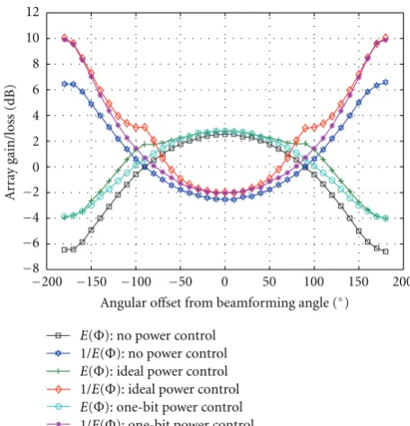
Figure 3captures the array gain (E[φ]) and array loss
(1/E[φ]) for varying offset angle. Given for comparison are
three cases: without power control, with ideal power control and with one-bit power control. While the range of angles over which E[φ] and 1/E[φ] is positive is 180◦ for the
nonpower-controlled case, the same exceeds 200◦with power
−200 −150 −100 −50 0 50 100 150 200
−8 −6 −4 −2 0 2 4 6 8 10 12
A
rr
ay
gain/loss
(dB)
Angular offset from beamforming angle (◦)
E(Φ): no power control 1/E(Φ): no power control
E(Φ): ideal power control 1/E(Φ): ideal power control
E(Φ): one-bit power control 1/E(Φ): one-bit power control
Figure3: The array gain seen in a 2 Tx×1 Rx antenna configuration for varying offset angle with 1−bit power control.
control. It can also be observed that power control using a single bit of information is very useful when the interfering link is made to operate as close as possible to the out-of-phase angle. Also observable is the fact that with power control, a part of the array gain lost due to the offset angle can be restored. When the interfering link is operating at the beam canceling angle, single-bit power control yields about 3 dB additional gain.
4. Proposed CPS-PC Algorithm
A heuristic algorithm for cooperative precoder selection with power control (CPS-PC) and multiuser scheduling, when BU is not large is explained in this section. We begin by first explaining CPS-PC without multiuser scheduling. The description of the algorithm needs an understanding of the manner in which the link behavior changes with the choice of precoderv. As per the algorithm (Algorithm 1), every UEk
computesLk j(v{a}),v{a} ∈Vfor theGk j link(s) seen from
BSj, j ∈ {k} ∪Sk, based on the reference signals (pilots)
used. There is a subset of precoding vectorsVF
k jofVgiving
a positive value (in dB scale) for Lk j, which we refer to
as cophasing vectors, while the complementary subset Vk jC which gives a negative value (in dB scale) are termed as canceling vectors. A vectorlk jof the indices inVis created by
sorting the correspondingLk j(v{a}),v{a}∈V, in decreasing
order. It may be noted thatv{l(1)j j}is the beamforming angle of BSj for UEj andv{l
(|V|)
k j }the beam canceling angle of BS
j
for UEk. Precoding its transmission using v{l (|V|)
k j } by BS
j
(1)for allisuch thati∈Kdo
(2) UEiidentifies BSj,j∈Si
(3) UEiestimatesGi j,j∈ {i} ∪Si {link quality estimate}
(4) UEicomputesli j,j∈ {i} ∪Si {sorted precoder index}
(5) UEicomputespi j,j∈ {i} ∪Si{power control choice}
(6) UEiforwards thepi js andli js to BSi{feedback on-air}
(7)end for
(8) BSiretainslii,piiand forwardsli j,pi j,j∈Sito BSj{feedback over back-haul}
(9) BSkserving{cell-edge}UEkchoosesv{l (1)
kk},pkkfor precoding transmission to UEk (10) BSj,j∈Skarrives atv{lo}for{precoding transmission to in-cell}UEjas follows
(11)forc= |V|to|V/2|do{least to minimal leakage} (12) for f=1 to|V/2|do{best to minimal array gain} (13) if l(j jf)=l(k jc)then
(14) lo←l(k jc){optimal value}
(15) gotostep (19)
(16) end if
(17) end for
(18)end for
(19)if pj j=pk j then
(20) BSj,j∈Skemployspo=pj j∈ {p{1},p{2}} {power control employed}
(21)else
(22) BSj,j∈Skemployspo= {p{3}} {uniform power employed}
(22)end if
Algorithm1: The CPS-PC algorithm without multiuser scheduling.
chooses a compromise precoderv{lo}which is in the setVF
j j∩
VC
k j. This choice of precoder can considerably minimize the
interference contributed to UEk, while restricting the loss
in array gain for UEj. In the rare case when VFj j ∩Vk jC =
φ (empty set), BSj picksv{l (|V|/2)
k j }, which also exists inVF
j j
(becauseVF
j j+VCj j=V).
Similarly, when the power level requested by the cell-boundary UE is the same as the value requested by the in-cell UE (pj j =pk j), then BSjemploys power levelpo(eitherp{1}
orp{2}) on the first antenna, defined byp
j j. Whenpj j=/ pk j,
then BSj employs p{3} on both its antennas. The different
UEi, i ∈ K make the necessary measurements and then
forward the quantized values (li and pi) to the serving
BSi. The information (li j and pi j) needed for cooperation
is then forwarded to the relevant cochannel BSj, j ∈Sivia
the backhaul communication links. BSjthen cooperates, also
taking into account the feedback received from UEj.
4.1. Causality of the CPS-PC Algorithm. In a general
coop-erative precoding setup, the choice of precoder made by a given BS depends on the choices made by the other BSs in the cochannel set. This leads to violation of causality in precoder selection, unless the base stations employ a centralized algorithm for coordination. To overcome this problem, we employ a user grouping framework as inFigure 4, whereby adjacent cell sites do not allot the same spectral resources simultaneously to users at the cell boundaries. In this framework, the entire frequency band is divided into three (logical) subbands and the low-SINR UEs are assigned a different third of the band by neighboring cell-sites
(cell-W1 W1 W1
p
ce
ll
1
p
ce
ll
2
p
ce
ll
3
Figure4: Spectrum sharing framework illustrated: the shaded part of the spectrum is used by cell edge users.
edge subband). The remaining UEs are scheduled in the remaining subbands (in-cell subband). In this framework, it is implicitly assumed that|Sk| = 2. While this type of
grouping is reminiscent of FFR [4], the spectral reuse here remains unity. Stated simply, this is a scheduling of UEs in the different cells, which ensures that a low-SINR UE gets interference only from BSs serving in-cell UEs on the same resource, which themselves do not require cooperation. In this setup it is the low-SINR, cell-boundary UE that requests cooperation from the interfering BSs. Each base station BSj, j ∈Sk serving in-cell UEj each choose a compromise
Table1: Gain and loss of CPS-PC.
BU CPS gain (dB) Avg. in-cell loss (dB)
1 1.90 0.56
2 3.65 0.27
4 4.91 0.12
UEk. In contrast, BSkemploys the optimal precoding vector
for beamforming to UEk. The actions of BSkare not of much
consequence to UEj,j ∈Sk, since these are high-SINR UEs
to which BSkdoes not generate much interference. Thus, the
distributed precoder selection at all BSs is rendered causal.
4.2. CPS-PC in Practice with Multiuser Scheduling. We
dis-cussed inSection 3.1that multiuser scheduling can mitigate the loss in performance of the in-cell UE due to cooperation asymptotically as BU → ∞. In Section 4, we discussed
Algorithm 1, which implements a compromise precoder selection without multiuser scheduling that minimizes the loss in performance for the in-cell UE. While such coop-eration helps in improving the performance of the cell-boundary UE, the performance of the in-cell UE would normally degrade because of the compromise precoder selected by its serving BS. However, in wide-band systems employing OFDM-based multiple access, one can employ user scheduling to make effective use of the multiuser diversity in the system and minimize the performance degradation. One simple, yet very useful, approach is for the scheduler to pair wherever possible a high-SINR UE, which happens to have the same precoder choice as the one requested by the cell-boundary UEkof the neighboring cell.
We now consider CPS-PC with multiuser scheduling and modest values for BandU, in order to overcome the loss in performance of in-cell UEs.
When multiuser scheduling is combined with the CPS-PC scheme, every BS schedules its own cell-boundary UEs in the cell-edge subbands based on the rates requested by them on each of the resource contended by them in these subbands. Typically, UEs requesting the highest rates are scheduled in those resources, which is also what we have adopted in our simulations. Once the cell-boundary UEs get scheduled, the corresponding precoder requests are shared with the interfering BSs. Based on the precoder requests received and such precoder requests from UEs associated with it, the BSs schedule the in-cell UEs on the in-cell subbands. This is done on a resource-by-resource basis. The BS tries to identify the UEs matching the same precoder requested by the cell-boundary UE, amongst those contenting for that resource. In case there is a match, the UE having the highest rate amongst them is scheduled. In the case when there is no match, the BS adds a rate offset to all those UEs contending, corresponding to a statistical measure of the offset angle given by their respective lk js,
and then schedules the UE with the given offset and serves with a correspondingly reduced rate. This continues, until a UE is identified to be scheduled on that resource. The probability of identifying an in-cell UE having the same
precoder request as the cell-boundary UE of an adjacent sector, or a corresponding compromise can be shown to be,
Prlo=lk j{i}
= ⎧ ⎪ ⎪ ⎪ ⎪ ⎪ ⎪ ⎪ ⎪ ⎪ ⎪ ⎪ ⎪ ⎪ ⎪ ⎪ ⎪ ⎪ ⎪ ⎪ ⎪ ⎪ ⎪ ⎪ ⎪ ⎨ ⎪ ⎪ ⎪ ⎪ ⎪ ⎪ ⎪ ⎪ ⎪ ⎪ ⎪ ⎪ ⎪ ⎪ ⎪ ⎪ ⎪ ⎪ ⎪ ⎪ ⎪ ⎪ ⎪ ⎪ ⎩ 1− 1 2 BU
, fori= |V|,
1−
i− |V|/2 i− |V|/2 + 1
BU
×
i− |V|/2 + 1 |V|
BU
, for|V|> i >|V| 2 ,
1 |V|
BU
, fori=|V|
2 ,
0 else where.
(9)
This probability is seen to be a function of the product BU. For the case whenNk = 1,Mk = 2 and|Sk| =2, for
allk, the array gain and loss for some typical values ofBU are given inTable 1. We can see that asBUapproaches even modest values such as 4, the loss incurred by the in-cell UE becomes negligible. Similarly, the choice of the power control parameters can be shown to have the following distribution,
Prpo=p{i}
= ⎧ ⎪ ⎪ ⎪ ⎪ ⎪ ⎨ ⎪ ⎪ ⎪ ⎪ ⎪ ⎩ 1 2 1− 1 2 BU
, fori∈ {1, 2}whenpj j=pk j
, 1 2 BU
, fori=3whenpj j=/ pk j
.
(10)
We have illustrated using system performance metrics in
Section 5that this cooperation strategy when combined with multiuser scheduling is indeed beneficial for both in-cell and cell-edge users. Note that this approach to cooperation requires knowledge of lk j and pk j corresponding to links
gk jof (cell-boundary) UEk at BSj. This requires a modest
amount of back-haul capacity between BSs, apart from the on-air feedback from UEk to BSk. This type of feedback
complements the link-adaptation-related feedback present in existing cellular systems. The UEs also need to know the choice made for v{lo} in order to equalize correctly. This can be either ensured through explicit feed-forward transmission, or by transmitting precoded pilots to facilitate estimation by UEj of the combined channel Gj jvj. CSI
acquisition and feedback between BSs is the price to be paid in order to achieve the true gains of such cooperation strategies. Given the complexity of network deployments and the sensitivity of this feedback information to delays and errors, it is necessary that the feedback rate be kept low, but made available via low-latency links.
With a modest amount of CSI exchange amongst adjacent cell BSs, this scheme enables the BSs to decide on a precoder that will minimize the signal strength leaked into adjacent sectors. The user grouping framework ensures that the precoder selection amongst cooperating BSs remain causal. It also ensures that interference-limited UEs benefit from a minimized interference leakage from adjacent cells. The number of dominant interferers is assumed to be two. However, this number can be extended to handle more interferers, provided the user grouping framework is appro-priately modified. Multiuser diversity scheduling ensures that the choice of precoder desired by the cell-edge UE can be ensured without compromising on the link performance of a cooperating BS to its own UE. Since the proposed scheme assumes the existing network infrastructure in its design, there is no need for any framework change for adoption into emerging broadband wireless systems.
5. Performance Results
In this section, we present simulation results for the proposed CPS-PC scheme. In the first part of this section, we com-pare, using link-level simulations, the proposed cooperation scheme with the MISO interference channel solutions in [27] and conventional single-cell beamforming. This is followed by numerical evaluation in the 3GPP LTE framework of the performance improvement possible with the proposed basestation cooperation scheme in a multicell, multiuser system, over single cell beamforming.
5.1. Link Performance Comparison. Figure 5 compares the average rate achieved, in terms of bits per-channel usage (bpcu) for varying signal-to-noise ratio (SNR), of the proposed CPS-PC scheme with the game-theory based solutions of zero-forcing and Nash equilibrium [26, 27]. Performance comparisons are made for a cell-boundary UE experiencing a signal-to-interference ratio (SIR) of 0 dB each from the cochannel transmission of two BSs, employing two antennas each. After including the thermal noise and residual interference, the effective SINR is well below−3 dB for this interference profile. The user grouping framework discussed in Section 4.1 is employed. The constant mod-ulus codebook introduced in Section 3.1 were employed in the simulations. The transmit power levels are either Pq = {(1/2)[1 + 1/
√
1 +π2/2], (1/2)[1−1/√1 +π2/2]}or Pq = {1/2, 1/2}. To ensure better averaging of the results,
snapshot simulationsspanning 105channel realizations were
performed. The beamforming-based schemes (cooperation with and without power control) employ codebooks of size 4 and 8, respectively, whereas in the case of zero-forcing and Nash equilibrium, ideal CSI is assumed to be available at the BSs. The averaging is done over 105channel realizations.
It can be seen fromFigure 5that the proposed cooper-ative precoding algorithms perform better than the game-theoretic solutions. This is due to the fact that the solutions based on game theory are inherently biased in favor of the entity with the highest bargain power (in this case, the in-cell UEs). At the Nash equilibrium point, the gain from
0 5 10 15
0.8 1 1.2 1.4 1.6 1.8 2
SNR (dB)
Rat
e
(bpcu)
Cooperation + power Cooperation Zero forcing Nash equilibrium
control
Figure5: Average rates for the different transmission schemes with 2-antennas at the basestation for varying average SNRs (all channels are i.i.d. Rayleigh fading).
single-cell precoding is maximized, but nothing is done to mitigate interference. In contrast, zero-forcing by a BS helps in minimizing much of the interference created to the adjacent cell user, without any regard to the performance of the link to its own UE. In the proposed cooperation algorithm, we allow the serving BSs to beamform to the cell-edge UEs and the interfering BSs (serving high-SINR UEs on cochannel resources) to reduce some of the interference they cause to the cell boundary UEs. At very high SNR, the ZF performance approaches the cooperation performance. However, in terms of feedback overhead needed, both the beamforming and cooperation schemes clearly have an edge.
5.2. System Performance Evaluation. While the link
simula-tions give a perception of how a typical cell-edge UE will perform, they do not capture the network level gains. To gain insight into this behavior we compare the gains of the proposed algorithm over the state-of-art in the 3GPP LTE framework.
5.2.1. Models and Assumptions. Some of the simulation
Table2: Simulation parameters.
Traffic models
User distribution Uniform
Data generation Full buffer
Data scheduling Round robin with persistent allocation Radio network models
Distance attenuation L=35.3 + 37.6 log(d),din metres
Shadow fading Log-normal, zero-mean with 8 dB standard deviation
Multipath fading 3GPP EPA model [36]
Cell layout 19-cell, 3 sectors/cell, hexagonal grid with wraparound Cell radius 1000 metres intersite distance
System models
Spectrum allocation 10 MHz bandwidth at 2 GHz
Doppler 5 Hz
Max antenna gain 15 dBi
Modulation and coding 3GPP specified [3]
Overhead 4 symbols in a subframe of 14 symbols
Feedback delay 2 msec
UE antennas 1/2 per UE with half-wavelength spacing,ρ=0.9 Network antennas 2 per site with 10-wavelength spacing
Users per cell 10, uniformly distributed
instantiations. The BSs are assumed to be interconnected via low-latency, low data-rate links.
The user grouping scheme illustrated in Figure 4 is employed. In each sector, the UEs starting from the lowest SINR are first scheduled in the one-third subband reserved for cell-boundary UEs in that sector. Once this subband is full, the remaining UEs are scheduled in the subband intended for in-cell UEs. Different UEs get serviced with different data-rates based on their instantaneous channel conditions. The different power levels employed remain the same as that inSection 5.1. The interference is modeled in the system based on the instantaneous SINR experienced by the UE. It is assumed that |Sk| = 2 for all UEs. In the
simulations, the ideal channel parameters are assumed to be available for all the links. A BS either beamforms on the resource allocated to its cell-boundary user, or cooperates for the cochannel neighboring cell-boundary user, while simultaneously serving its in-cell user as best it can by exploiting multiuser diversity.
Since the performance improvement with basestation cooperation is dependent on the quality of CSI information estimated by the UEs and fed back to the BSs, a 5% channel estimation error, modeled as zero-mean, complex Gaussian is assumed and added to the ideal channel parameters. A single transmission per coded block, matched to the channel conditions is considered, and hybrid-ARQ is modeled as in [37]. Based on the precoder chosen, the channel realization and the active interferer set, a SINR is calculated for each link assuming a MMSE receiver model at 10% block-error rate, and then an effective SNR is calculated per downlink resource block (the time-frequency resource allocated to an user). This SNR is mapped to active radio-link data rates for each active user using the EESM prediction model [38]. In
−10 −5 0 5 10 15 20
0 0.2 0.4 0.6 0.8 1
SINR (dB)
F
(
x
)
Figure6: CDF of SINR experienced by a user.
practice, the network will train over the initial few subframes to arrive at the correct modulation and coding level. Since, we assume persistent scheduling for the users over tens of subframes, the prediction model can be assumed to be valid for the entire allocation. The mean and 5th percentile point of spectral efficiency are used as the metrics for average and cell-edge performance, respectively, which provide useful insight into system behavior.
5.2.2. Numerical Results. Simulation results are presented
for the two cases where the UEs employ 1 and 2 antennas, respectively. We have used a codebook with four precoding vectors (i.e., |V| = 4 andθx = n(π/2), n ∈ {0,. . ., 3}).
0 0.5 1 1.5 2 2.5 3 3.5 4 0
0.1 0.2 0.3 0.4 0.5 0.6 0.7 0.8 0.9 1
Spectral efficiency (bps/Hz/cell)
CDF
o
f
user
Single-cell beamforming
Cooperation without power control Cooperation with power control
Figure7: CDF of Spectral Efficiency when UEs employ one antenna each.
the serving BS for each of the B = (5) resources. There is a natural ordering of precoding vectors with respect to Lk j(v{a}). With cooperation, the in-cell UEs feed back
2 bits for the optimal precoding vector and 1 additional bit to indicate the direction in which one should move in the naturally-ordered codebook, when the BS seeks to cooperate. With power control, one more additional bit will be employed to indicate which of the two antennas should transmit with the higher transmit power. A cell-edge UE will thus feed back 3 bits (2 + 1) to its serving BS and 4 bits (2 + 1 + 1) for every cooperating BS, for each of theB resources.
InFigure 7, the SE comparisons are made for the single receive-antenna case. Conventional single-cell beamforming is compared against cooperation, with and without power control. The mean SE for the three different schemes are 1.38, 1.60, and 1.77 bps/Hz/cell and the 5th percentile values are 0.13, 0.23, and 0.28 bps/Hz/cell, respectively. Cooperation helps to improve the fifth percentile point and mean spectral-efficiency values by 77% and 16%, respectively. With power control, the corresponding improvement values are about 115% and 28%, respectively. There is a significant improve-ment in performance of the proposed cooperation scheme when power control is employed. It may be noted that the gains accrue because of both cooperation and multiuser scheduling. While cooperation ensures that the performance of the cell-boundary, low-SINR user improves, the in-cell user’s performance (in the form of average throughput) does not degrade because of multiuser scheduling.
InFigure 8, the SE comparisons are made for the two-receive-antenna case. Conventional single-cell beamforming is compared against cooperation, with and without power control for a correlation coefficient ρ = 0.9. To illustrate how much rate is lost because of correlation, the single-cell beamforming scheme is also compared with a value for ρ = 0. In this case, the receiver can support dual-stream spatial multiplexing when in-cell, and does MMSE
0 0.5 1 1.5 2 2.5 3 3.5 4 0
0.1 0.2 0.3 0.4 0.5 0.6 0.7 0.8 0.9 1
Spectral efficiency (bps/Hz/cell)
CDF
o
f
user
1. Single-cell beamforming,ρ=0.9
2. Cooperation without power control,ρ=0.9 3. Cooperation with power control,ρ=0.9 4. Single-cell beamforming,ρ=0
4 3 2
1
Figure 8: CDF of Spectral Efficiency with ρ = 0.9 and UEs employing two antenna each.
processing to mitigate some interference for cell-edge UEs. The mean SE of conventional beamforming for ρ = 0 and ρ = 0.9 are 1.94 and 1.40 bps/Hz/cell, respectively, and the 5th percentile values are 0.45 and 0.08 bps/Hz/cell, respectively. The correlation takes away about 28% of the mean SE gains and the 5th percentile value falls by about 82%. With ρ = 0.9, mean SE value increases to 1.76 and 1.91 with and without power control, whereas the 5th percentile value increases to 0.26 and 0.32, respectively. This corresponds to a 26% and 37% improvement in the mean SE and 225% and 300% for the 5th percentile value, respectively. While the improvements seem to be very high, it may be noted that 0.32 bps/Hz/cell/user is in itself a modest value in absolute terms.
6. Conclusions
gains characterized in terms of the mean and 5% tail values in the spectral efficiency CDF were also provided.
The precoder-selection based algorithm for base sta-tion cooperasta-tion was shown to be useful in improving the performance of cell-edge users without compromising on the mean spectral efficiency. When employing power-control based cooperation, a mean spectral efficiency value improvement of about 28% is reported over conventional single-cell beamforming for a system with two transmit antennas and one receive antenna. For a system where user terminals are equipped with two receive antennas, but there is a high correlation factor 0.9 between them, a mean spectral efficiency gain of 37% is reported. It was shown that this approaches the performance of single-cell beamforming when there is no antenna correlation. The algorithm employed was shown to be simple, requiring only modest overhead when compared with single-cell MIMO signalling schemes. Furthermore, the algorithm facilitates a causal implementation of distributed precoder selection for base station cooperation. In contrast to the CPS-PC scheme, where UEs are scheduled across sectors on the same resource, in multiuser MIMO [39], UEs on the same sector with orthogonal precoder requests are scheduled on the same resource. Whereas MU-MIMO improves the cell-capacity with almost similar cell-edge performance as of single-cell beamforming, the CPS-PC scheme improves the cell-edge performance without loss in cell-capacity when compared to single-cell beamforming. Thus the two schemes employ MIMO primarily to achieve different ends.
References
[1] E. Dahlman, S. Parkvall, J. Skold, and P. Beming,3G Evolution: HSPA and LTE for Mobile Broadband, Academic Press, San Diego, Calif , USA, 2nd edition, 2008.
[2] S. Sesia, I. Toufik, and M. Baker,LTE—The UMTS Long Term Evolution: From Theory to Practice, John Wiley & Sons, New York, NY, USA, 2009.
[3] Third Generation Partnership Project (3GPP), “Evolved UTRA aspects: Physical Layer Procedures (3GPP TS 36.2xy series documents),” ETSI, 2008.
[4] J. G. Andrews, W. Choi, and R. W. Heath, “Overcoming interference in spatial multiplexing mimo cellular networks,” IEEE Wireless Communications, vol. 14, no. 6, pp. 95–104, 2007.
[5] G. Boudreau, J. Panicker, N. Guo, R. Chang, N. Wang, and S. Vrzic, “Interference coordination and cancellation for 4G networks,”IEEE Communications Magazine, vol. 47, no. 4, pp. 74–81, 2009.
[6] C. Rose, S. Ulukus, and R. D. Yates, “Wireless systems and interference avoidance,” IEEE Transactions on Wireless Communications, vol. 1, no. 3, pp. 415–428, 2002.
[7] O. Popescu, C. Rose, and D. C. Popescu, “Signal space partitioning versus simultaneous water filling for mutually interfering systems,” inProceedings of the IEEE Global Telecom-munications Conference (GLOBECOM ’04), pp. 3128–3132, December 2004.
[8] S. Ulukus and R. D. Yates, “Iterative construction of optimum signature sequence sets in synchronous CDMA systems,”IEEE Transactions on Information Theory, vol. 47, no. 5, pp. 1989– 1998, 2001.
[9] S. A. Jafar and M. J. Fakhereddin, “Degrees of freedom for the MIMO interference channel,”IEEE Transactions on Information Theory, vol. 53, no. 7, pp. 2637–2642, 2007. [10] S. Vishwanath and S. A. Jafar, “On the capacity of vector
gaussian interference channels,” in Proceedings of the IEEE Information Theory Workshop (ITW ’04), pp. 365–369, Octo-ber 2004.
[11] V. R. Cadambe and S. A. Jafar, “Interference alignment and degrees of freedom of the K-user interference channel,”IEEE Transactions on Information Theory, vol. 54, no. 8, pp. 3425– 3441, 2008.
[12] K. Gomadam, V. R. Cadambe, and S. A. Jafar, “Approach-ing the capacity of wireless networks through distributed interference alignment,” in Proceedings of the IEEE Global Telecommunications Conference (GLOBECOM ’08), pp. 4260– 4265, New Orleans, La, USA, December 2008.
[13] J. G. Andrews, “Interference cancellation for cellular systems: a contemporary overview,”IEEE Wireless Communications, vol. 12, no. 2, pp. 19–29, 2005.
[14] H. Dai, A. F. Molisch, and H. V. Poor, “Downlink capacity of interference-limited MIMO systems with joint detection,” IEEE Transactions on Wireless Communications, vol. 3, no. 2, pp. 442–453, 2004.
[15] B. L. Ng, J. S. Evans, S. V. Hanly, and D. Aktas, “Distributed downlink beamforming with cooperative base stations,”IEEE Transactions on Information Theory, vol. 54, no. 12, pp. 5491– 5499, 2008.
[16] A. B. Carleial, “Outer bounds on the capacity of interference channels,”IEEE Transactions on Information Theory, vol. 29, no. 4, pp. 602–606, 1983.
[17] G. J. Foschini, K. Karakayali, and R. A. Valenzuela, “Coor-dinating multiple antenna cellular networks to achieve enor-mous spectral efficiency,”IEE Proceedings, vol. 153, no. 4, pp. 548–555, 2006.
[18] H. Zhang and H. Dai, “Cochannel interference mitigation and cooperative processing in downlink multicell multiuser MIMO networks,”EURASIP Journal on Wireless Communica-tions and Networking, vol. 2004, no. 2, pp. 222–235, 2004. [19] M. K. Karakayali, G. J. Foschini, R. A. Valenzuelat, and R.
D. Yates, “On the maximum common rate achievable in a coordinated network,” inProceedings of the IEEE International Conference on Communications (ICC ’06), vol. 9, pp. 4333– 4338, Istanbul, Turkey, June 2006.
[20] H. Zhang, N. B. Mehta, A. F. Molisch, J. Zhang, and H. Dai, “Asynchronous interference mitigation in cooperative base station systems,”IEEE Transactions on Wireless Communica-tions, vol. 7, no. 1, pp. 155–165, 2008.
[21] M. Sadek, A. Tarighat, and A. H. Sayed, “A leakage-based precoding scheme for downlink multi-user MIMO channels,” IEEE Transactions on Wireless Communications, vol. 6, no. 5, pp. 1711–1721, 2007.
[22] H. Boche and M. Schubert, “A general theory for SIR balancing,”EURASIP Journal on Wireless Communications and Networking, vol. 2006, Article ID 60681, 18 pages, 2006. [23] H. Boche and S. Sta ´nczak, “The infeasible SIR region is not a
convex set,” inProceedings of IEEE International Symposium on Information Theory (ISIT ’05), Adelaide, Australia, September 2005.
[24] H. Boche and M. Schubert, “Resource allocation in multi-antenna systems—achieving max-min fairness by optimizing a sum of inverse SIR,”IEEE Transactions on Signal Processing, vol. 54, no. 6, pp. 1990–1997, 2006.
approach,” inProceedings of the IEEE 19th International Sym-posium on Personal, Indoor and Mobile Radio Communications (PIMRC ’08), Cannes, France, September 2008.
[26] E. A. Jorswieck and E. G. Larsson, “THE MISO interference channel from a game-theoretic perspective: a combination of selfishness and altruism achieves Pareto optimality,” in Proceedings of the IEEE International Conference on Acoustics, Speech and Signal Processing (ICASSP ’08), pp. 5364–5367, Las Vegas, Nev, USA, April 2008.
[27] E. G. Larsson and E. A. Jorswieck, “Competition versus cooperation on the MISO interference channel,”IEEE Journal on Selected Areas in Communications, vol. 26, no. 7, pp. 1059– 1069, 2008.
[28] E. A. Jorswieck, E. G. Larsson, and D. Danev, “Complete char-acterization of the pareto boundary for the MISO interference channel,”IEEE Transactions on Signal Processing, vol. 56, no. 10, pp. 5292–5296, 2008.
[29] W. Yu, W. Rhee, S. Boyd, and J. M. Cioffi, “Iterative water-filling for Gaussian vector multiple-access channels,” IEEE Transactions on Information Theory, vol. 50, no. 1, pp. 145– 152, 2004.
[30] I. Sohn, S. H. Lee, and J. G. Andrews, “A graphical model approach to downlink cooperative MIMO systems,” in Pro-ceedings of the IEEE Global Telecommunications Conference (GLOBECOM ’10), Miami, Fla, USA, December 2010. [31] Third Generation Partnership Project (3GPP), “Physical Layer
aspects for evolved UTRA (3GPP TR 25.814),” 3GPP, 1999. [32] D. J. Love and R. W. Heath, “Limited feedback unitary
precoding for spatial multiplexing systems,”IEEE Transactions on Information Theory, vol. 51, no. 8, pp. 2967–2976, 2005. [33] WP-5D, “Guidelines for evaluation of radio interface
tech-nologies for IMT-advanced,” Tech. Rep. M.2135, 2008. [34] D. J. Love, R. W. Heath, V. K. N. Lau, D. Gesbert, B. D. Rao,
and M. Andrews, “An overview of limited feedback in wireless communication systems,” IEEE Journal on Selected Areas in Communications, vol. 26, no. 8, pp. 1341–1365, 2008. [35] W. Choi and J. G. Andrews, “The capacity gain from intercell
scheduling in multi-antenna systems,”IEEE Transactions on Wireless Communications, vol. 7, no. 2, pp. 714–725, 2008. [36] Third Generation Partnership Project (3GPP), “Evolved
Uni-versal Terrestrial Radio Access (E-UTRA); Base Station (BS) Radio Transmission and Reception (3GPP TR 36.104),” ETSI, 2008.
[37] B. Classon, P. Sartori, Y. Blankenship, K. Baum, R. Love, and Y. Sun, “Efficient OFDM-HARQ system evaluation using a recursive EESM link error prediction,” in Proceedings of the IEEE Wireless Communications and Networking Conference (WCNC ’06), pp. 1860–1865, April 2006.
[38] K. Brueninghaus, D. Ast´elyt, T. Salzer et al., “Link performance models for system level simulations of broadband radio access systems,” inProceedings of the IEEE 16th International Sym-posium on Personal, Indoor and Mobile Radio Communication (PIMRC ’05), pp. 2306–2311, September 2005.