Hybrid Power Generation System with Energy
Management Algorithm for the Effective
Storage of Energy in Battery and
Supercapacitor
J.Karthika
1, Dr.V.Subbiah
2, Dr. S. Kanthalakshmi
3Assistant Professor, Department of EEE, Sri Krishna College of Engg & Tech, Coimbatore, Tamil Nadu, India1
Visiting Professor, Department of EEE, PSG College of Technology, Coimbatore, Tamil Nadu, India2
Associate Professor, Department of EEE, PSG College of Technology, Coimbatore, Tamil Nadu, India3
ABSTRACT: Due to the sporadic nature of wind, a wind turbine generator alone will not be able to supply all the active and reactive power required by the load at all times in a standalone operation. A solar PV array is integrated in to it forming a Hybrid Power Generation System. A standalone operation of a hybrid generating system under fluctuating wind and varying irradiation is a challenging task. Due to the constraint of reactive capability of the hybrid generation system, high reactive power demand makes it more challenging. A Remote Area Power Supply (RAPS) system consists of a Solar PV Array, Permanent Magnet Synchronous Generator (PMSG), a Hybrid Energy Storage, Dump Load and Main Loads. The Hybrid Energy Storage System consists of a Battery Storage and a Supercapacitor; both are connected to the common DC Bus of the RAPS System. A New Energy Management Algorithm (EMA) is proposed for the effective storage of energy in battery and supercapacitor. It also improves the performance and Life of the battery. A Synchronous Condenser is used to provide the reactive power and an additional support to the RAPS system. The active and reactive power flow among the RAPS components are controlled by a coordinated controller. Apart from this an individual controllers for each RAPS component has been advanced for the effective management. The simulation is carried out using detailed model in MATLAB Simulink. From the simulation results it has been revealed that the system has good frequency and voltage regulation, Effective management if energy in battery and supercapaitor, better reactive power capability and maximum power extraction from solar and wind.
KEYWORDS: PMSG, PV Array, Battery, Supercapacitor - Energy Storage System, Remote Area Power Supply, Synchronous Condenser.
I. INTRODUCTION
storage systems perform in a hybrid fashion [6]. A good knowledge about the operational characteristics is required for the proper selection of the energy storage system. Generally, battery and supercapacitor provides high energy and power requirements respectively. The integration of a supercapacitor guarantees a healthy operation of the battery storage by avoiding it to operate in high Depth of Discharge (DOD) regions and low frequency power regions.
Fig.1 Proposed Hybrid RAPS System
Permanent Magnet Synchronous Generator (PMSG) has many advantages but not limited to self-excitation capability but allows operation at improved efficiency, high power factor, high reliability, MPPT and good control performance [7]. In this paper, various components performance of a Hybrid RAPS system is examined under varying wind speed, varying irradiation and variable load conditions. The proposed Hybrid RAPS System is shown in fig. 1. The PMSG and PV array performs as the main hybrid source of energy while the hybrid energy storage along with the dump load performs as auxiliary system. This is to extract the maximum power from the wind and solar and also to keep the active power balance of the RAPS system. The synchronous condenser is integrated into the RAPS system to provide improved reactive power and inertial support.
The proposed work on the RAPS system with energy storage is briefed here. An isolated operation of a PMSG with battery storage system is discussed in [8]. It covers a RAPS system consists of PMSG and battery storage. The maximum energy of solar PV module endlessly changes with the atmospheric conditions; a real-time maximum power point tracker is the vital part of the solar PV system. Many MPPT algorithms have been presented in the literature [9-13] but most of them have limitations due to non-linear behaviour of the solar PV module. Multilevel energy storage with a flow battery storage and supercapacitor is explained in [14]. However, authors have presented the hybrid energy storage system rather than system level behaviour. Various control strategies have been proposed for the battery – supercapacitor hybrid energy storage in [15]. Authors in [16] have presented a method to improve the battery life in a small-scale remote area with a use of battery/supercapacitor hybrid energy storage system. However, the management and control of RAPS system consisting of PMSG, PV Array, hybrid energy storage, dump load and a synchronous condenser have received a very little research attention. In this paper, the RAPS system is modelled and a coordinated control approach for power management is proposed. This is to make the RAPS system to operate during under and over generation scenarios. Based on the demand-generation variations of the RAPS system, a new power sharing strategy is proposed for the effective energy storage in battery and supercapacitor. The main objective of the proposed method is to control the operation of the Hybrid Energy Storage system. The battery is used to mitigate low frequency oscillations and the supercapacitor is to mitigate high frequency oscillations. The Energy management strategy is implemented during the Maximum Power Point Tracking in both solar and wind. Reactive power management is based on the integration of the synchronous condenser.
II.CONTROL STRATEGY FOR THE RAPS SYSTEM
To achieve the voltage and frequency regulation of the system it is important to maintain the active and reactive power balance as given,
2
0
KESources Sinks
P
P
dt
dt
d j
dE
- (1)
0
Sources Sinks
Q
Q
- (2)Where P –active power,
E
KE - Kinetic energy of the system, J – moment of inertia of rotating machine and Q-reactivepower. In RAPS system, the active power flow is coordinated with the PV array, wind turbine generator, batter storage, supercapacitor and dump load is given by
w s b c L d
P
P
P
P
P
P
- (3)Where
P
w- wind power output,P
s- solar power output,P
b- battery storage output,P
c- supercapacitor output,P
L- active power demand,P
d- dump load power. In order to balance the RAPS system a coordinated control approach is developed in Fig.2.Fig. 2. Proposed Coordinated Control Method
During the over generation conditions i.e., the power output from the solar (
P
s) and wind generator (P
w) is greater than the load demand (PL) then the hybrid energy storage (battery and supercapacitor) should absorb the excess power (Pw Ps
P
L) based on the Energy Management Algorithm. If the ESS reaches their maximum limits i.e. SOC maxand VSC max, where SOC max is the maximum state of charge of the battery and VSC max is the maximum operating voltage
of the supercapacitor, the dump load absorbs the excess power. If the dumb load
P
dreaches its maximum valueP
dmax,then the pitch control of the wind turbine is activated. During the over generation conditions, where
P
w
P
sP
L
0
, then the hybrid energy storage is capable of supplying the required power into the system. Assumptions are made that the power generated by the wind and solar and hybrid energy storage are sufficient to supply the load demand at all time. However, the unexpected situations such as reduced wind speed, very low irradiations are not considered, but the load shedding mode can be activated during that time. The reactive power sharing is made between synchronous condenser and inverter is represented asinv syn L
Where Qinv- inverter reactive power, Qsyn- reactive power from synchronous condenser, QL- reactive power demand of mains loads.
III. CONTROL TECHNIQUES FOR PMSG
The solar and wind acts as the main source of energy and is interfaced with an uncontrolled rectifier-inverter arrangement. Then it is connected to the main loads. A control scheme is developed for the Line Side Converter (LSC) and DC/DC converter which is explained in this session.
A. Line Side Converter:
The converter is modelled as a voltage controlled voltage source inverter. The objective is to control the magnitude and frequency of the load side voltage. The vector control has been active to develop the control associated with the LSC. The voltage balance across the filter is given by,
1 1 1
a a a a
b b b b
c c c c
V i i V
d
V R i L i V
dt
V i i V
- (5)
1
a
V
,V
b1,V
c1- voltage at the inverter outputi
a,i
b,i
c- current through the filter circuitV
a,V
b,V
c- voltages at load side. R and L are the resistance and Inductance of the filter circuit. These parameters are then transformed into a synchronously rotating d-q coordinates with angular velocity ωs. A Phase Lock Loop is used for the orientation of θ forthe inverter to achieve a constant frequency of RAPS system. As shown in fig.3 the reference d-component of the voltage is maintained at 1pu (Vds=1pu), whereas the reference q-component of the load voltage is set to 0 pu (Vqs=1pu).
The PI controllers associated with LSC are properly tuned using internal mode control principle [17].
B. DC/DC Converter:
The Common DC bus voltage of the RAPS system is regulated using DC/DC boost converter. The rectified voltage (Vdc) unreg output at the full converter diode bridge is a function of generator speed ωg. The proposed control scheme for
the DC/DC converter is shown in Fig. 4
Fig.4 DC/DC Converter
The outer loop measures the DC link voltage Vdc which is compared with reference DC link voltage Vdc ref. The error is
corrected using a PI controller to generate the reference current through the inductor of the boost converter Idc ref.
This is then compared with the actual current Idc and the error is again corrected through the second PI controller to
generate the switching signal for the DC-DC converter. The highest boosting factor bf is recorded at the lowest
generator speed.
(
i
dc ref)
v
dck
pk
is
- (6)max
1
(
)
( )
(
)
dc ref f
dc unreg
v
b
v
- (7)Where, (idc ref) is the reference current through the inductor,
k
p,k
iare the proportional and integral components of the PI controller, (vdc ref) is the regulated common DC bus voltage, (vdc unreg) 1is the lowest unregulated voltage at theoutput of the rectifier.
IV. SOLAR POWER GENERATION
The general PV panel can be modelled using the equivalent circuit shown in Fig.5. This lumped circuit includes a current generator providing the short circuit current Isc, which is a function of the solar irradiation.
Fig.5 PV Panel Model
The characteristic of the solar cell is dependent upon the temperature and array voltage. So it is necessary to implement MPPT in order to change the operating voltage close to maximum power point under changing atmospheric conditions. While using the MPPT in solar, it reduces the solar array cost by decreasing the number of solar panels needed to obtain the desired output.
0 0
0
exp
(
1
s g sat
q V
I R
I
I
I
AKT
Incremental conductance method is an alternative to P&O method where solar array terminal voltage can be adjusted relative to the MPP voltage by measuring the incremental and instantaneous array conductance (dI/dV and I/V). To overcome the limitations of P&O by using the incremental conductance, compute the sign of dP/dV without perturbation. It does this by using expression dP/dV = 0 which represents MPPT in Fig.6.
Fig.6 Variation of dP/dV
0
1
dP dV dI
I V
dV dV dV
dI
dV V
- (9)
dP/dV is negative when the current operating point is on the right of MPPT and positive when it is to the left of MPPT.
V. ENERGY MANAGEMENT ALGORITHM FOR BATTERY AND SUPERCAPACITOR
A. Battery Model:
The Nickel-Cadmium battery model is used in this paper. The capacity of the battery storage system reduces dramatically under high DODs. Therefore, in real time simulation, it is vital to regulate the State of Charge (SOC) of the battery within the safe limits. The battery storage capacity is estimated using
(
)
60
rated
t
ratingI
Ah
- (10)
- Fraction of the rated current of the load demand,I
rated- is the rated current of the load demand,t
- is the time duration that battery provides power into the system,
- a fraction that defines the average discharge /charge current of the battery. It is assumed that battery storage is used to supply 40 % (
=0.4) of the rated load current for the time duration of 30 min.The size of the battery can be estimated by first calculating the rated current of PMSG,
(
)
3
PMSG rated ratedrated
P
I
V
- (11)
Also the rated current of the solar panel has to be calculated. Therefore, the total rated current is
(Itotal rated) (Irated PMSG) (Irated solar) - (12)
B. Supercapacitor Model:
Based on the operating frequency range, there are two different models of a supercapacitor. (i) High frequency model (ii) Low frequency model. The high frequency model includes the non-linear Faraday capacitance. The low frequency domain model which can be used under power system operating frequency range is used as shown in Fig.7.
Fig.7 Low Frequency Model
For the smooth operation of the system, the supercapacitor needs to satisfy certain conditions. (i) Safe operating voltage as indicated in the manufacturer data sheet (13). (ii) Maximum possible peak current of a supercapacitor (14). (iii) Maximum allowable power from the supercapacitor during its operation (15).
min max
sc sc sc
V
V
V
- (13)sup sup
0.5
( )
(
) 1
sc c pk dc
C
V
i
C
ESR
- (14)max sup
max
sc
c
dv
P
C
Vsc
dt
- (15)
sc
V
- the capacitance value of the supercapacitor,V
scmin&V
scmaxare the minimum and maximum operating voltagesrespectively,
ESR
dc- the equivalent series resistor of the supercapacitor,P
cmax - the maximum power rating of thecapacitance,
dv
scmax
dt
is the maximum rate of change of voltage across the supercapacitor. The size of the supercapacitor can be calculated using the formulas shown below.
2 s
1
sup2
c sc
E
C
V
- (16)
2 2
max min
s
1
sup1
sup2
2
c sc sc
E
C
V
C
V
- (17) 2 2 max min s sup
2
c sc scE
C
V
V
- (18)Where,
E
sc- the energy rating of the supercapacitor,V
scmax&V
scminare the maximum and minimum operating voltages of the supercapacitor. The size of the supercapacitor is determined by assuming the safe operating voltage limits of the supercapacitor.C. Energy Management Algorithm:
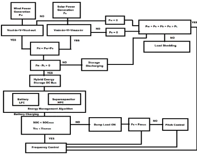
Fig.8. Energy Management Algorithm
To meet the first objective the input signal to EMA is selected as the demand-generation mismatch, (Pw+Ps)-PL. The
second objective is realized by finding the optimal wind power (Pw) opt. This power is used to derive the input signals to
the battery and supercapacitor. By controlling the power flow into the battery and supercapacitor using maximum power point tracking algorithm, it is possible to impose an appropriate torque TPMSG on the shaft to extract maximum
power from the wind.
The third objective is obtained by splitting the demand-generation mismatch into two frequency components by means of a high-pass filter as shown infig.8 The high frequency components is used to generate the reference capacitor current, which is compared with the actual capacitor current to generate switching pulse to converter C1. The low frequency components is used to estimate the reference battery current, which is compared with the actual battery current to generate switching pulse to converter C2.
VI. OPERATION OF SYNCHRONOUS CONDENSER AND DUMP LOAD
The synchronous condenser is used to operate at leading power factor region to supply reactive power into the RAPS system. A synchronous machine with an exciter is used for the simulation, where the active power input to the synchronous machine is set to zero. An IEEE type I voltage regulator and exciter system [18] is used to control the field voltage of the synchronous condenser. The dump load is added to maintain the active power in the RAPS system. The dump load can be a water heater or a space heating system. Here the dump load is represented by a series of resistors which are connected across switches. The dumb load will absorb the additional power only after the battery storage reaches its maximum capacity (Pb) max. The maximum power that can be dissipated through a dump load can be
expressed as
max
(
P
dump)
(2
n
1)
P
step- (19) Where n is the number of three phase resistive elements and
P
stepis the power that can be absorbed per resistor step.VII.Simulation Results
Fig.9. Voltage and Current at the Load side
The effectiveness of integrating hybrid energy storage into a RAPS system is examined by the behaviour of the battery current with and without supercapacitor. Without supercapacitor we can clearly see the high frequency components which will shorten the lifespan of the battery. With integration of hybrid energy storage, it is clearly seen that the high frequency components are absorbed by the supercapacitor and provides a smooth transition from one operational mode to another with low DOD value.
Fig.10. Real and Reactive Power without Synchronous Condenser
Fig.11. Real and Reactive Power with Synchronous Condenser
Fig.10 & 11 shows the comparison of the real and reactive power without and with synchronous condenser.
VIII. CONCLUSION
DOD value. By using proper MPPT technique the power balance is achieved for the entire RAPS system. By integrating the synchronous condenser, reactive power demand is maintained within the acceptable limits.
REFERENCES
[1]. Nishad Mendis, Kashem M. Muttaqiand Sarath Perera, “Management of Battery-Supercapacitor Hybrid Energy Storage and Synchronous Condenser for Isolated Operation of PMSG Based Variable-Speed Wind Turbine Generating Systems” IEEE TRANS. SMART GRID, VOL. 5, NO. 2, PP. 944-953, MARCH 2014.
[2]. F. Liu, J. Liu, and L. Zhou, “A novel control strategy for hybrid energy storage system to relieve battery stress,” in Proc. Int. Symp. Power Electron. Distrib. Gener. Syst. (PEDG), Hefei, China, Jun. 16–18, 2010, pp. 929–934.
[3]. A. Ter-Gazarian, Energy Storage for Power Systems. London, U.K.: Peter Peregrinus, 1994, pp. 36–36.
[4]. C. Abbey and G. Joos, “Short-term energy storage for wind energy applications,” in Proc. Ind. Appl. Soc. Annu.Meet., Hong Kong, China, Oct. 2–6, 2005, vol. 3, pp. 2035–2042.
[5]. L. Wei and G. Joos, “A power electronic interface for a battery supercapacitor hybrid energy storage system for wind applications,” in Proc. Power Electron. Specialists Conf., Rhodes, Greece, Jun. 15–19, 2008, pp. 1762–1768.
[6]. L. Wei, G. Joos, and J. Bélanger, “Real-time simulation of a wind turbine generator coupled with a battery supercapacitor energy storage system,”
IEEE Trans. Ind. Electron., vol. 75, no. 4, pp. 1137–1145, Apr. 2010.
[7]. M. E. Haque, M. Negnevitsky, and K. M. Muttaqi, “A novel control strategy for a variable-speed wind turbine with a permanent-magnet synchronous generator,” IEEE Trans. Ind. Appl., vol. 46, pp. 331–339, Nov. 2009.
[8]. M. Singh and A. Chandra, “Control of PMSG based variable-speed wind-battery hybrid system in an isolated network,” in Proc. Power Energy Soc. Gen. Meet. (PESGM), Calgary, AB, Canada, Jul. 26–30, 2009, pp. 1–6.
[9]. V. Lingareddy, G. Ravichandra and P. K. Maddukrui, “Effective Strategy for MPPT in PV/Wind Hybrid Electric Power System Interconnected with Electrical Utility Grid,” International Journal of Advanced Research in Computer Science and Software Engineering. Volume 3, Issue 7. July 2013.
[10]. S. D. Saravana, “Modeling and Simulation of Incremental Conductance MPPT Algorithm for Photovoltaic Applications,” International Journal of Scientific Engineering and Technology, ISSN: 2277-1581, Volume No.2, Issue No.7, pp: 681-685. 1 July 2013.
[11]. M. Lokanadham and K. V. Bhaskar, “Incremental Conductance Based Maximum Power Point Tracking (MPPT) for Photovoltaic System,”
International Journal of Engineering Research and Applications (IJERA), ISSN: 2248-9622, Vol. 2, Issue 2, pp.1420-1424. March-April 2012. [12]. C. Chukwuka and K. A. Folly, “Technical and Economic Modeling of the 2.5kW Grid-Tie Residential Photovoltaic System,” International Journal of Renewable Energy Research. Vol.3, No.2. 2013.
[13]. M. K. Gupta and R. Jain, “MPPT Simulation with DC Submersible Solar Pump using Output Sensing Direct Control Method and Cuk Converter,” International Journal of Renewable Energy Research. Vol.3, No.1. 2013.
[14]. H. Jia, Y. Fu, Y. Zhang, and W. He, “A design of hybrid energy storage control system for wind farms based on flow battery and electric double-layer capacitor,” in Proc. Asia-Pacific Power Energy Eng. Conf. (APPEEC), Chengdu, China, Mar. 28–31, 2010, pp. 1–6.
[15]. Y. Zhang, Z. Jiang, and X. Yu, “Control strategies for battery/supercapacitor hybrid energy source systems,” in Proc. IEEE on Global Sustain.Energy Infrastructure, Atlanta, GA, USA, Nov. 17–18, 2008, pp. 1–6.
[16]. A. M. Gee, F. V. P. Robinson, and R. W. Dunn, “Analysis of battery lifetime extension in a small-scale wind-energy system using supercapacitors,” IEEE Trans. Energy Convers., vol. 3, pp. 24–33, Feb. 2013.
[17]. L. Harnefors and H. P. Nee, “Model-based current control of AC machines using the internal model control method,” IEEE Trans. Ind. Appl., vol. 34, pp. 133–141, Jan./Feb. 1998.
[18]. S. Sayeef, N. Mendis, and K. Muttaqi, “Enhanced reactive power support of a PMSG based wind turbine for a remote area power system,” in