Smart Farming System Design Using
Wireless Sensor Networks
Nanthini.N
1,Sasikumar.D
2, SelinFranciesca.S
3, Vaani.N
4, Yogeswaran.E
51,2,3,4,5
Department of Electronics and Communication Engineering, Maharaja Engineering College, Avinashi,
Tamilnadu, India
ABSTRACT: Recent development in the areas of information and communication detonated the emergence of a new paradigm of ubiquitous and smart environment. A ubiquitous environment is a technology that the computer and communication are to control and monitor all the matters without human‟s direct involvement in control. So this paper purports to explain about the general installation method and the efficacy and how to use the monitor and control system in the growing environment by using the wireless sensor network technology, and to design and propose the smart farming system with convenience and easiness to use even in the narrowenvironments.
I.INTRODUCTION
Recent development in the areas of information and communication detonated the emergence of a new paradigm of ubiquitous and smart environment. A ubiquitous environment is a technology that the computer and communication are to control and monitor all the matters without human‟s direct involvement in control. By combining such ubiquitous environment with the sectors related to agriculture, and the simple and convenient farming such as house agriculture and dairy industry became available in the cities.
During the last 10 years, it was revealed that the agricultural population in Korea has been reduced by 34.7%, and the aging of rural farmhouses as well as the rural exodus and move-out phenomena have been continuously increasing. The proportion of full-time farmers accounts for 813,000 people as 64.3% and has been declined by 5.7% compared to the Figure of last year. Such decrease of rural population and lack of agricultural competitiveness due to their aging are acting as a maladaptive factor along with the issues of the outdate technology and equipment‟s caused by the financial troubles.
In this regard, the controlling technology is recently being developed in the agricultural sector Around the world to collect the weather and environment information of the crop production areas by using the communication methods to monitor the changes on the temperature and humidity and soil conditions in order to optimize the growing environment for the crops by using such collected data [1].
However, as most of the monitor and control systems for the growing environments have been materialized as the systems controlled via the conventional wired communication or manually for the relatively wide greenhouses, they are not suitable to apply to the environment of remote areas such as the places where the cultivation areas be narrow or the mountainous regions due to the difficulties in the installation and maintenance of the systems. To resolve these problems, it is via the wireless communication which enables to easily produce the crops even in then arrow Environments to build up the systems to monitor and control the growing. In addition, it is the current situation that most of the existing greenhouse monitoring systems had been installed through the introduction of foreign systems. Such systems are mainly monitoring the changes of temperature and humidity and only controlling to maintain the temperature via the wired communication.
Also, the producer should reside in the control room of the greenhouse and process it manually for monitoring and controlling. However, in the narrow environments or mountainous regions, there is the limitation from the aspect that a person should reside and manually process it.
for the optimized
cultivation environments, and which enables to collect and analyze such collected data in the sensor node and to store them in the control sever and to alert the emergency situation so as to monitor and adjust the temperature and humidity automatically and to use the water level adjustment function with no need of a person attended but only through the system.
In addition, it implements the user‟s application program based on PC/Smartphone to be the real-time monitoring system available for the real-time remotemonitoring.
II.EMBEDDED SYSTEM
Embedded System is a computer system designed to perform only one or more specific functions [3]. Specifically, embedded system means a system with processor, memories and in/output integrated with software to control that hardware to perform specific objectives. Generally, consist of microprocessor and ROM containing software and running the application software to perform specific objective once powered on [3].
Embedded system is departing from old role of computer which is responsible for analogical calculation with hardware oriented interface, it is mounted on any product or solution for human oriented and conative information processing and growing as the center of the future industry but there is no separate legal definition. From structure of developing software to enable specific function and mount on the hardware (microprocessor), it can be classified into software development and embedded system application productdevelopment.
2.1. ZigBeeNetwork
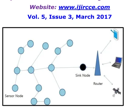
ZigBee wireless communication is a system collecting sensing data from surrounding environment and objects from multiple numbers of small sensor nodes installed in specific area or space and implementing forapplication services. Wireless sensor network is differentiated from existing network focusing on reciprocal information transfer by automated remote information c o l l e c t i o n .
Radio and small sensor node implementing technology is essential to enable wireless sensor network, especially sufficient consideration for battery powered low power output environment as the radio which consuming more electricity for wireless communication comparing to electricity required for sensing and data process[7].
Figure 1. The Basic Configuration of Sensor Node
III.SMART FARMING SYSTEM DESIGN
Smart farming system is classified by the water tank unit, cultivation unit, and environmental control unit. The water tank unit of smartfarming system is on the first floor where water is contained for the crops.
Using a submersible pump from the water tank unit, water is being pulled up and supplied to the cultivation unit on the second floor. Water level indicator is installed in the water tank unit and the real-time water level is being measured, of which data is transmitted to the remote location via a wireless communication device.
At the remote location, the received water level is checked and whether to supply water and to which cultivation unit is determined.
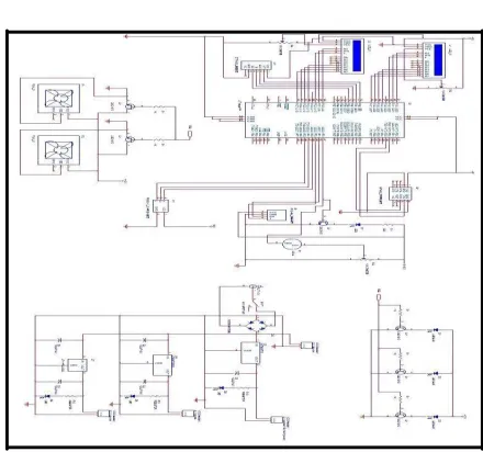
Figure 3. Smart Farm System Circuit Diagram
At the cultivation unit on the second floor, a temperature sensor and a humidity sensor and an ambient light sensor are installed to measure the temperature and humidity of the cultivation environment in real time, and, through the environment control unit on the third floor, such sensor data values are received to the remote location. An ambient light sensor also measures the amount of lights in the cultivation unit and receives the measured values to the remote location through the environment control unit, and embodies the function to control the lights by controlling LED automatically[8].
Also, a monitoring program called as the control system is to be manufactured by comprising API programs based on Visual C# for the user to handle it with ease. Figure 2 shows a Smart Farming System Block Diagram using the sensor network. Smart Farming System Block Diagram using the sensor network has been developed mainly being divided into water level control unit, sensor network processing unit, sensor unit, and controlunit.
Figure 3 shows the circuit diagram of Smart Farming System using the sensor network. This system is composed of the water level measurement unit, sensor network processing unit, sensor unit, and control unit.
Figure 4 shows the ports using ATmega 2560. Such AVR micro controller family is using the core of the same structure, of which basic structure and command are same and their handling methods are very similar.
The differences from ATmea128 are the speed of CPU or the size of internal memory, whether or not various features to be built in etc. ATmega 2560 is the micro controller with AVR Core in the structure of 8 bit RISC (Reduced Instruction Set Computer) and implements most of commands via Single Cycle. [7].
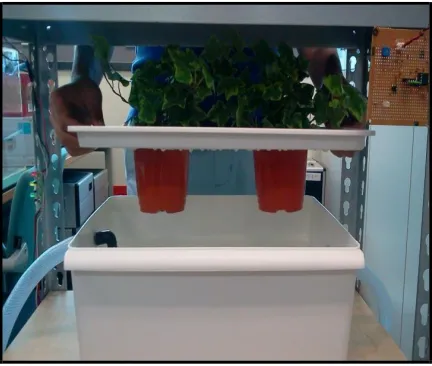
Figure 5. Smart FarmSystem
Figure 5 depicts the Smart Farming System. ATmega 2560 inside of the Smart Farming System chip is composed of the oscillation circuit, GPIO input and output ports, Timer/Counter, RTC (Real Time Clock), USART ((Universal Synchronous Asynchronous Receiver and Transmitter)and SPI(Serial Peripheral Interface), PWM(Pulse Width Modulation), ADC(Analog to Digital Converter), Analog Comparator, Watchdog Timer, I2C, of which structure is not to receive data under the specificcondition but periodically at the designated intervals as its features of hardware and it is suitable for the polling type [7].
Setting the main measuring devices of the ambient light sensor, the temperature sensor, the humidity sensor and the water level adjustment sensor and determining the baud rate of the wireless transmission and environment control units, thefarming environment data are to be sent out wirelessly.
Figure 6. Level Control Using the Water Level Sensor
The principle of water level indicator in the Figure 6 is; as shown in the Figure 6, “P” point is connected to a 100 ohm resistor and receives + electrode voltage. “P”point current flows along the point “1”. At this moment, water level indicates 1level and the voltage flows across a 100 ohm resistor (R1) and passes by the water in the water tank and reaches the base of TR1. Then, the LED light of TR1 turns on. If all the points of“1”, “2” and “3” are soaked in the water, all 3 LED lights will turn on as the voltage flows from “P” point across R1, R2, and R3 and reaches the bases of TR1, TR2,TR3.
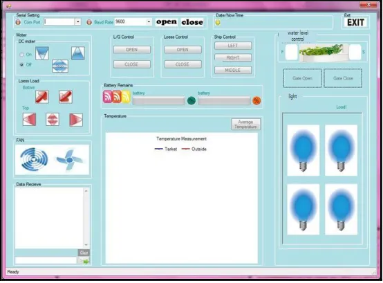
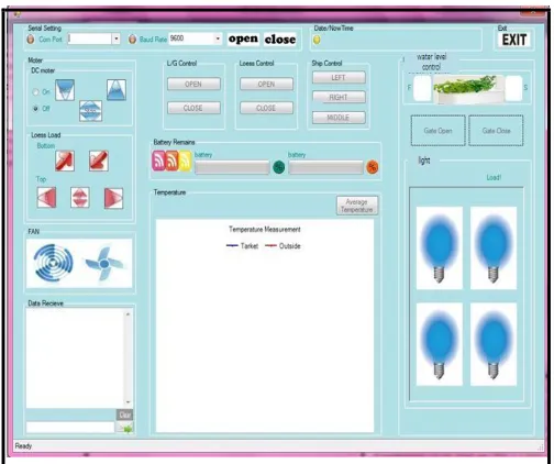
3.1. Smart Farming Remote Control System
As seen in the Figure 7, the monitoring management equipment is composed of the blocks for communication, the operation of the water level control motor, for measuring power, temperature and ambient lights. Communication block uses the wireless sensor network communication for the transactions between the monitoring management equipment and each sensor node, and informs of the display setup and the status of water level in accordance with the operation of water level control motor. Temperature and ambient light blocks are the parts to display the current status of temperature and ambient light of each sensor node, when the communication is normally functioning.
Figure 8. Sensor Measurement Data
We programmed the software to fulfill the system purposes in order to perform all these functions and to design the operational circuit for all the associated devices. In addition, API program was developed by using C# program suitable for monitoring the accumulated real time environment data byperiod/time.
Figure8 illustrates the windows to verify the assessed data by sensors in the form of diagram. It consists of ①
Figure 9. Smart Farms Information Measurement System
Also, Smartphone-based user‟s applications developed by the android app allows the user to
connect with the subscribed mobile communication network and to check the environment data accumulated in the management server database through internet in real time.
III.CONCLUSIONS
We materialized the real time monitoring system that is to collect the smart farming system data periodically in order for the user to monitor the environment status at various platforms, and to improve the quality of produces and to increase the productivity through the accumulated environment factor data, and to defined the risky range of each environment factors, and in excessive of the allowances, to alert the risk audio-visually to the user for his speedy confrontation with such risks through SNS, buzzer etc.
The system was studied and developed to configure of the wireless sensor network to assess the temperature, humidity and water level adjustment, and of the sensor node necessary for the optimal farming environment, and of the monitoring management devices to collect and analyze such collected data from sensor node and to store them in the management server and to alert emergency.
Also, materializing the user‟s applications based on PC/Smartphone for real time remote monitoring, we realized it as the user-oriented system.
REFERENCES
[1] E. P. C. Jones, M. Karsten and P. A. S. Ward, “Multipath load balancing in multi-hop routing in wireless sensor networks”, in Proceeding
IEEE Wireless Mobile Computer Networking, Commun, Montreal, Canada, (2005), pp. 158-166.
[2] J. M. Kang, T. W. Yoo and H. C. Kim, “A wrist-worn integrated health monitoring instrument with a tele-reporting device for telemedicine
and tele-care”, IEEE Transactions on Instrumentation and Measurement, vol. 55, no. 5, (2006), pp. 1655-1661.
[3] C. S. Park and P. H. Chou, “Eco: ltra-wearable and expandable wireless sensor platform”, Proceedings of the International workshop on
Wearable and Implantable Body Sensor Network, (2006), pp.158-162.
[4] S.Waharte and R. Boutaba, “Totally disjoint multipath routing in multihop wireless networks,” in Proceeding IEEE International Conference
Commun. (ICC „06), Istanbul, Turkey, (2006), pp. 5576- 5581.
[5] M. Radi, B. Dezfouli, K. A. Baker and M. Lee, “Multipath routing in wireless sensor networks: survey and research challenges”, Sensors, vol. 12, no. 1, (2012), pp.650-685.
[6] C. S. Park, J. F. Liu and P. H. Chou, “Eco: an ultra-compact low-power wireless sensor node for real- time motion monitoring”, Information Processing in sensor Networks, pp.398-403.
[7] Q. S. Correal, N. Kyperountas and S. F. Niu, “Performance comparison between TOA ranging technologies and rssi ranging technologies for
multi-hop wireless networks”, IEEE VTC,(2005).
[8] J. Choi, D. Shin and D. Shin, “Research and implementation of the context-aware middleware for controlling home appliance”, IEEE
Transactions on Consumer Electronics, vol. 51, no. 1, (2005), pp. 301-306.
[9] Y. J. Jang, S. Y. Bae and S. K. Lee, “An Energy-Efficient Routing Algorithm in Wireless Sensor Networks”, Future Generation