University of Windsor University of Windsor
Scholarship at UWindsor
Scholarship at UWindsor
Electronic Theses and Dissertations Theses, Dissertations, and Major Papers
11-27-2018
Optimal RWA for SDM Optical Network under Dynamic Traffic
Optimal RWA for SDM Optical Network under Dynamic Traffic
Dhruvi Patel
University of Windsor
Follow this and additional works at: https://scholar.uwindsor.ca/etd
Recommended Citation Recommended Citation
Patel, Dhruvi, "Optimal RWA for SDM Optical Network under Dynamic Traffic" (2018). Electronic Theses and Dissertations. 7619.
https://scholar.uwindsor.ca/etd/7619
This online database contains the full-text of PhD dissertations and Masters’ theses of University of Windsor students from 1954 forward. These documents are made available for personal study and research purposes only, in accordance with the Canadian Copyright Act and the Creative Commons license—CC BY-NC-ND (Attribution, Non-Commercial, No Derivative Works). Under this license, works must always be attributed to the copyright holder (original author), cannot be used for any commercial purposes, and may not be altered. Any other use would require the permission of the copyright holder. Students may inquire about withdrawing their dissertation and/or thesis from this database. For additional inquiries, please contact the repository administrator via email
Optimal RWA for SDM Optical Network under dynamic
traffic
By
Dhruvi Patel
A Thesis
Submitted to the Faculty of Graduate Studies
through the School of Computer Science
in Partial Fulfillment of the Requirements for the
Degree of Master of Science
at the University of Windsor
Windsor, Ontario, Canada
2018
c
Optimal RWA for SDM Optical Network under dynamic traffic
By
Dhruvi Patel
APPROVED BY:
Z. Hu
Department of Mathematics and Statistics
A. Ouda
School of Computer Science
Y. Aneja, Co-Advisor
Odette School of Business
A. Jaekel, Advisor
School of Computer Science
DECLARATION OF ORIGINALITY
I hereby certify that I am the sole author of this thesis and that no part of this thesis has
been published or submitted for publication.
I certify that, to the best of my knowledge, my thesis does not infringe upon anyones
copyright nor violate any proprietary rights and that any ideas, techniques, quotations, or
any other material from the work of other people included in my thesis, published or
oth-erwise, are fully acknowledged in accordance with the standard referencing practices.
Fur-thermore, to the extent that I have included copyrighted material that surpasses the bounds
of fair dealing within the meaning of the Canada Copyright Act, I certify that I have
ob-tained a written permission from the copyright owner(s) to include such material(s) in my
thesis and have included copies of such copyright clearances to my appendix.
I declare that this is a true copy of my thesis, including any final revisions, as approved
by my thesis committee and the Graduate Studies office, and that this thesis has not been
ABSTRACT
With the rapid increase in demand for data transmission in our generation where Internet
and cloud concepts play an essential role, it has become mandatory that we handle data
most efficiently. A promising solution to overcome the capacity crunch problem which is
so evident in future is applications of Space Division Multiplexing, where we explore the
remaining unused domain that is the spectral and spatial domain. Space Division
Multi-plexing using multi-core fibers (MCF), and few-mode fibers (FMF) has been studied in our
work to enhance the data-carrying capacity of optical fibers while minimizing the
trans-mission cost per bit. The objective is to develop a path protection scheme to handle
com-munication requests in the data center (DC) networks using elastic optical networking and
space division multiplexing (SDM). Our approach to this problem is to 1) determining the
initial allocation of light path on the topology, 2) possible spectrum allocation using the
flex-grid flexible-SDM model, 3) choose the best possible route to minimize the number of
subcarriers needed for data transfer. We propose to evaluate the developed Integer Linear
DEDICATION
Dedicated to my grandmother
Late Shri Shardaben Patel
, my
parents
Manubhai and Komalben Patel
, and my brother
ACKNOWLEDGMENT
I would like to express my sincere gratitude to my advisor Dr. Arunita Jaekel andDr.
Yash Aneja for their continuous support in my research, for their patience, motivation,
and immense knowledge. Their guidance helped me throughout my time of research and
writing of this thesis. I could not have imagined having better mentors for my study.
I would also like to thank my thesis committee membersDr. Abdelnasser OudaandDr.
Zhiguo Hufor their valuable comments and suggestions for the completion of this thesis. I
would like to sincerely thankDr. Saja Al Mamoori, who has been the fundamental support
throughout my work.
Also, I would like to thank Parth Patel and Meet Patel, who has been encouraging
elements during the development of this work. Last but not the least, my deepest gratitude
TABLE OF CONTENTS
DECLARATION OF ORIGINALITY . . . iii
ABSTRACT . . . iv
DEDICATION . . . v
ACKNOWLEDGMENT . . . vi
LIST OF FIGURES . . . ix
LIST OF TABLES . . . x
LIST OF SYMBOLS . . . xi
1 INTRODUCTION . . . 1
1.1 Overview of the Networks . . . 1
1.2 Motivation of our work . . . 3
1.3 Problem Statement & Solution Outline . . . 4
1.4 Structure of the thesis . . . 5
2 REVIEW OF RELATED TOPICS . . . 7
2.1 Fundamentals of Optical Networks . . . 7
2.1.1 Components of Optical fiber . . . 8
2.1.2 Total Internal Reflection . . . 9
2.2 Optical Networks in Cloud Computing . . . 10
2.3 Data Centers in Cloud Computing . . . 11
2.4 Wavelength Division Multiplexing . . . 12
2.4.1 Process of Wavelength Division Multiplexing . . . 12
2.4.2 Types of multiplexers for Wavelength Division Multiplexing . 14 2.4.3 Lightpaths Establishment in Wavelength Division Multiplexing 14 2.5 Routing and Wavelength Assignment . . . 15
2.5.1 Static Routing and Wavelength Assignment . . . 16
2.5.2 Dynamic Routing and Wavelength Assignment . . . 16
2.6 Optical Orthogonal Frequency Division Multiplexing . . . 17
2.7 Routing and Spectrum Allocation . . . 19
2.8 Space Division Multiplexing . . . 19
2.8.1 Types of Fibers used in SDM . . . 21
2.8.2 Ways of realizing SDM Transmission . . . 23
2.9 Optical Reach . . . 25
2.10 Modulation Format . . . 26
2.11 Literature Review . . . 27
3 OPTIMAL RSA FOR SDM OPTICAL NETWORK UNDER DYNAMIC TRAFFIC . . . 33
3.1 Introduction to the problem . . . 33
3.2 Assumptions . . . 34
3.3 The Objective of our Approach . . . 34
3.4 Virtual Node . . . 35
3.5 Concept of Gaps . . . 37
3.6 Notations used in the ILP . . . 40
3.8 Justification of ILP . . . 43
3.9 Example of our Approach . . . 45
4 SIMULATION AND RESULTS . . . 51
4.1 Simulation . . . 51
4.1.1 Simulation Setup . . . 52
4.1.2 Topology Used for Simulation . . . 55
4.2 Performance Study . . . 57
4.2.1 Blocking Probability and Resource Utilization vs Traffic Load 58 4.2.2 Blocking Probability vs Number of Cores . . . 59
4.2.3 Blocking Probability vs Number of Requests . . . 60
5 CONCLUSIONS AND FUTURE WORK . . . 62
5.1 Conclusions . . . 62
5.2 Future Work . . . 62
BIBLIOGRAPHY . . . 64
LIST OF FIGURES
2.1 Optical Cable . . . 8
2.2 Total Internal Reflection . . . 10
2.3 Wavelength Division Multiplexing . . . 13
2.4 Physical and Logical topology . . . 15
2.5 Static and dynamic Traffic . . . 16
2.6 Spectrum in WDM . . . 17
2.7 Spectrum in OFDM . . . 18
2.8 Orthogonality in OFDM . . . 18
2.9 Six node network topology for SDM . . . 20
2.10 Multiple core division in SDM . . . 21
2.11 Single mode fiber . . . 21
2.12 Multi core fiber . . . 22
2.13 Fewer-mode and Multi-mode fiber . . . 22
2.14 SDM Model: Fixed-grid- Single . . . 23
2.15 SDM Model: Flex-grid- Single . . . 24
2.16 SDM Model: Flex-grid/Fixed . . . 24
2.17 SDM Model: Flex-grid/Semi-Flexible . . . 24
2.18 SDM Model: Flex-grid/Flexible . . . 25
2.19 Optical Reach . . . 26
3.1 Six node network topology with a virtual node at 0 . . . 36
3.2 A six node network topology with data centers . . . 37
3.3 Available spectrum . . . 38
3.4 Bandwidth allocation on available spectrum . . . 39
3.5 Concept of Gaps . . . 39
3.6 Bandwidth allocation in gaps . . . 40
3.7 Six-node topology with Distance . . . 45
3.8 Before allocation of the new request . . . 46
3.9 Calculating gaps . . . 47
3.10 Possible allocation . . . 48
3.11 Allocation of the new request . . . 49
3.12 Resource allocation using Modulation Format . . . 50
4.1 Flow diagram for simulation setup . . . 53
4.2 8-Node Network . . . 56
4.3 COST239 Network . . . 56
4.4 NSFnet Network . . . 57
4.5 Blocking Probability in Flexgrid/Flexible and Flexgrid/Fixed for multiple data rate of traffic . . . 58
4.6 Resource Utilization in Flexgrid/Flexible and Flexgrid/Fixed for multiple data rate of traffic . . . 59
4.7 Blocking Probability vs Number of Cores . . . 60
LIST OF TABLES
LIST OF SYMBOLS
Symbol Definition
bps/Hz bytes per second per Hertz
BPSK Binary Phase Shift Keying
DWDM Dense Wavelength Division Multiplexing
EON Elastic Optical Network
FMF Few-mode Fiber
Gbps Gigabytes per second
GHz Giga Hertz
ICT Information and Communication Technology
ILP Integer Linear Program
LtoSR Light path-to-Spatial-Resource
Mbps Megabytes per second
MCF Multi Core Fiber
MCM Multi-Carrier Modulation
MMF Multi Mode Fiber
OC Optical Carrier
OFDM Orthogonal Frequency Division Multiplexing
PDM Polarization Division Multiplexing
QAM Quadrature Amplitude Modulation
QPSK Quadrature Phase Shift Keying
RSA Routing and Spectrum Allocation
RSCA Routing, Spectrum and Core Allocation
RWA Routing and Spectrum Assignment
SDM Space Division Multiplexing
SMF Single Mode Fiber
SpRcs Spectral and Spatial Resources
TDM Time Division Multiplexing
Tbps Terabytes per second
WAN Wide Area Network
WDM Wavelength Division Multiplexing
Chapter 1
INTRODUCTION
1.1
Overview of the Networks
Initially, the computer communication started over the copper wire as a medium of carrying
electrical signals encoding the data to communicated from one computer to the another [1].
To overcome the limitation of copper wires with increasing Internet traffic, progress has
been made in using alternative media of communication such as optical networks.
Opti-cal fibers are essentially very thin glass cylinder or filaments which carry signals in the
form of the light (i.e., optical signals). The network in which the dominant physical layer
of technology for transport in optical fiber is known as optical network [1]. The optical
network provides a means of communication in which electrical signals are converted into
modulated optical signals for communicating data from specified source nodes to specified
destination nodes in the network [2]. Optical networks are dominant in the Information and
Communication Technology (ICT) sector because of their all-optical approach for a
wide-area network, where the required information can be transmitted in the optical domain
between nodes, which may be hundreds or even thousands of kilometers apart, without any
conversion to the electrical domain.
Optical fibers provide a higher rate of data communication, compared to copper wires
[1]. It is cheap and more resilient towards electromagnetic interference, carries a
tremen-dous amount of information and capable of covering long distance without signal
degrada-tion. Optical fibers have a high bandwidth capacity of Gigabytes per second (Gbps) [3]. In
other words, the capability to send 40Gbps to 100Gbps on a single strand is now
Optical fiber carries some optical signals with different carrier wavelengths simultaneously
on the same fiber with WDM. WDM is an optical technique which can combine optical
sig-nals of different wavelengths onto a single strand of optical fiber. It is achieved by adding
multiplexer at the transmitters end and the demultiplexer at the receivers end [4]. The
ad-vent of WDM technology has helped in increasing the capacity of the network without the
installation of more fibers.
The inflexible nature of WDM networks create limitations on efficient network
utiliza-tion. In the WDM network, there is a mismatch of granularities between the client layer,
which possess a board range of capacity demands with granularities of several gigabits per
second to 100 Gbps or more, and the physical wavelength layer, which has a rigid and large
granularity of a wavelength [5]. For instance, when the end-to-end client traffic is not
suffi-cient to fill the capacity of the wavelength, the residual bandwidth of wavelength is wasted.
It is known asstranded bandwidth issue. Although, when the requested end-to-end
capac-ity is higher than the wavelength, several wavelengths are grouped and allocated according
to the request. The adjacent wavelengths in such groups have to be separated by a buffer in
the spectral domain for wavelength demultiplexing, which leads to spectral efficiency [5].
Orthogonal Frequency-Division Multiplexing (OFDM) technology is recently introduced
as a promising solution for high-speed optical transmission. The modulation technique
in OFDM achieves better spectral efficiency, flexibility, and tolerance to impairment [5].
OFDM delivers the required capacity of bandwidth depending on the demand size. Thus,
higher bandwidth capacity can be achieved with an order of Terabits per second (Tbps)
using OFDM.
The IP traffic is growing with the Compound Annual Growth Rate (CAGR) of 22%
from 2015 to 2020 [6]. Progress has been made in finding the innovative idea to increase
the capacity of carrying data on a single optical fiber, hence minimizing the number of
dimension. Thus, Space Division Multiplexing (SDM) in optical networks seems to be an
upcoming significant solution to overcome the capacity crunchproblem in the backbone
networks [8]. In SDM, a single fiber is replaced with multiple cores and used in parallel
transmissions. It enables higher data transmission by using the same resources
simultane-ously, hence saves both time and resources and leads to a potential reduction in cost and
required energy [8].
1.2
Motivation of our work
Optical networks are the backbone of modern communication networks, carrying data
rate anywhere from a few kilometers to miles on a transcontinental scale. Earlier in the
1980s, when optical fibers started to substitute copper wire, the first-generation systems
operated at bit rates if 50 Megabytes per second (Mbps) and required support from
re-peaters every 10 km. However, the current updated long-haul networks offer 100 Gbps
per wavelength [4]. With the advancement of smart devices, video-based application, and
development in communication between devices the data traffic is increasing rapidly with
no sign of slowing down. According to the present scenario, 100 Gbps technology will be
able to serve for a few years but will not be enough for future demands [3]. Therefore,
researchers are investigating alternative solutions for the required data rates of 400 Gbps
and 1Tbps over 1000km [4]. For that, the first step would be exploring various
modula-tion formats to obtain higher spectral efficiency (i.e., how much data rate can be supported
for a limited spectral bandwidth). The next step is the use of super-channels that include
multiple subcarriers beyond the 50 GHz grid [8]. Even after such advancement, the data
transfer capacity will remain limited, so that 400 Gbps and 1 Tbps running on legacy
sys-tems will be unable to bridge distances greater than 2000 km in the long links with high
km for single-mode fiber (fibers allowing a single light signal to propagate) of less than 7
bps/Hz [8] (Spectral efficiency is measured in b/s/Hz, by dividing maximum throughput
with bandwidth in Hertz). There are various approaches to increase optical transmission
system capacity over a fixed bandwidth, one of them is using an available space
dimen-sion [8]. Space Dividimen-sion Multiplexing has been proposed as a solution to enhance the
capacity minimizing the cost per bit of fiber optic transmission [9] [1].
1.3
Problem Statement & Solution Outline
Over a few decades, researchers are accomplishing modeling and optimization of the
communication networks. However, the networks have undergone important changes driven
by the emergence and rapid expansion of new services. The concepts of cloud computing
are the most significant technologies that have gained wide interest [10]. Cloud computing
revolutionized various ways to deliver end-users, network services through Internet
irre-spective to their physical locations. The key issue is to model and optimize the network
with the dynamic traffic patterns to allow the cost-effective implementation of recent
net-working services with Quality of Service (QoS) and high scalability [10]. In general, the
cloud is a virtual data repository which refers to accessing computer, software
applica-tion, and information technology through a network connection. It is often accessing by
data centers using Wide Area Networking (WAN) or Internet connectivity [11]. The idea
of a data center is known as a centralized repository which can be physical or virtual for
maintenance of data [12]. Methodologies had to be modified from WDM when it began
including DCs as it considers data storage in various location. Subsequently, it has drifted
to Elastic Optical systems enable every communication to dynamically adjust its resources,
depending on the transmission characteristic and bandwidth requirements for the
commu-nication [13]. A large portion of current work on DCs focuses on static lightpath allocation
sce-nario expects that the paths should be allocated on user demand and resources should be
restored after a significant period, such that the freed resources can be reused for a different
communication.
In this thesis, we address this approach with optimal utilization of the spatial and spectral
resources for Space Division Multiplexing Optical Network. Considering dynamic
alloca-tion of the user requests such that the demands are tear-down after a significant amount
of time. SDM enables parallel transmission of optical signals propagating through spatial
channels in fiber optic media. Here, spatial expansion reflects either multiple fibers, cores,
or modes or a group of cores with few modes, which are capable of multi-carrier
transmis-sion (i.e., super-channel transmistransmis-sion) [14]. Current, WDM networks possess single-carrier
transmission, within a fixed frequency grid where only one optical channel is used, and
can-not be split in the spatial domain. Such a network is inflexible in both spectral and spatial
domains. For achieving flexibility in the spectral domain, the flexible grid was introduced
in an elastic optical network (EON) architecture [13]. Furthermore, for the spatial domain,
the parallel channels are added. Thus, transmission of high-capacity super-channel over a
network may consist of some optical carriers (OCs) which are generated/ terminated
us-ing the transceiver devices, each of them usus-ing certain modulation format and carryus-ing a
multiple of aggregated traffic [14].
1.4
Structure of the thesis
The remaining chapters are organized as follows. In Chapter 2, we discuss basic concepts
of the optical networks based on SDM. We present our proposed approach in Chapter 3 with
a detailed explanation of ILP formulation which is a primary contribution of our thesis.
In chapter 4 we describe the implementation details of our proposed approach, and the
simulation results to support the thesis. We compare our results with the ILP formulation
Chapter 2
REVIEW OF RELATED TOPICS
2.1
Fundamentals of Optical Networks
Over a past decade of years, networks are evolving rapidly from being relatively static,
hav-ing uniform traffic to behav-ing more configurable and providhav-ing a complex number of services.
Computer communication had started with copper wires as the medium of communication
that carries electrical signals, encoding the data to transmit from one device to another.
However, the important limitation of copper as a medium of communication is its
rela-tively high attenuation, provides limited bandwidth, susceptibility to malicious attacks, and
electromagnetic interference. Therefore, in the past two decades, enormous progress has
been made in using alternative media for communication. The enormous growth in the
us-age of Internet services has made high-bandwidth computer communication an important
and strategic infrastructure. Deregulation of the telephone industry and the dramatic
in-crease of data, as opposed to voice, traffic over communication networks have also spurred
the deployment of high-speed networks.
The rapid growth of optical networks is primarily due to inherent high speed and the
reliability of optical communication. Initially, the optical networks simply replaced copper
wire with optical cables, to take advantage of the higher bandwidth of optical
communica-tion, while handle switching and other network operations before. The speed of electronic
processing lead to bottleneck for such networks. Hence, the switching, the routing, and
many other network operations perform at the optical level. The optical networks are being
increasingly deployed to meet the increasing demand for high-speed backbone networks
The optical network can define as a technological arrangement of signals that connects
more than a single computer or any devices which can generate or store data in electronic
format using optical fibers. It consists of some nodes which are interconnected using optical
fibers and possesses the ability to carry out communication across the network using optical
signals. Both local area networks, as well as wide area networks, use it. It can carry large
amounts of data at high speed and over long distances. Not only does it provide a higher
capacity but is also cost-effective, hence can be efficiently used for new applications on the
Internet, Cloud Computing or other Multimedia interaction.
Figure 2.1: Optical Cable
2.1.1 Components of Optical fiber
The internal construction of an Optical Fiber consists of five layers as shown in Figure
2.1:
• Core - The physical layer that is a continuous glass strand, that transports the
optical data signals. The cores diameter in microns [1].
• Cladding - The second layer that covers the core as a protective sheath and
causes the reflection to allow light to transmit through the inner fiber-core
• Plastic Coating - The thick plastic layer surrounds the cladding and helps
pro-tect the fiber core [15].
• Strengthening fibers - The strengthening fibers that help protect the core against
damage during installation or from being crushed [15].
• Cable jacket - Lastly, the outer layer of fiber is wrapped in a cable jacket to
protect against elements [15].
The light transmission in an optical fiber is the total internal reflection when the angle of
incidence exceeds a critical value, and light cannot get out of the glass; instead, it bounces
back in. Hence, the light can quickly move down the fiber-optic line. It is possible to
transmit information down fiber optic cables in the form of light pulses. Therefore, plastic
and glass are the primary materials for optical fibers.
In comparison to the core, cladding has a relatively lower refractive index to keep the
light signals inside the core. Optical signals travel down a fiber-optic cable by repeatedly
bouncing off the boundary between core and cladding. When an optical signal hits the glass
at an angle less than the critical angle, it reflects in again due to total internal reflection.
A very minimal loss during transmission allows Optical Fibers to transmit light or data
quickly over long distance.
2.1.2 Total Internal Reflection
The Total internal reflection occurs when a propagating light waves strike a surface or
a medium at a point (i.e., which makes an angle) which is greater than a critical angle
concerning the normal to the surface. The refraction index of glass or an optical material is
a measure of the speed of the light in the material, and any change in this index of refraction
angle; hence this reflection is used by the optical fiber to trap light in the core of the fiber,
which has a proper index of refraction.
Figure 2.2: Total Internal Reflection
2.2
Optical Networks in Cloud Computing
With the recent and significant advances in Information and Communication
Technol-ogy (ICT), cloud computing appears to be a commodity model for our generation after
water, electricity, gas and telephony [16]. In the Cloud Computing model, the user
ac-cesses the data services by the requirement irrespective of location, time or device, if they
are connected to the Internet. It is the high capacity Internet-based computing which
re-quires large data centers to store the data. For convenience and prompt access to distributed
and powerful computing (data centers) and networking resources is critical for
provision-ing high-quality services for intensive data applications. Therefore, to facilitate efficient
interworking of the computing, storage resources, and networking in the new generation
networks for cloud services; Optical networking technology plays an essential role in
real-izing cost-effective interconnection of a wide variety of resources over a highly distributed
computing environment [17]. In other words, Cloud Computing is a techno-scientifically
• It is largely scalable,
• It can be encapsulated as an abstract entity that delivers various levels of the
services outside the cloud,
• It is driven by markets of scale, and
• The services can be dynamically configured (via virtualization or other
ap-proaches) and delivered on demand.
Generally, research institutes, industry leaders, Government are adopting Cloud solution
to solve massive data exchange and processing arising in this Internet Era [17].
2.3
Data Centers in Cloud Computing
Cloud Computing relies on the compute and storage infrastructure provided by the data
centers [18]. The data center centralizes the IT operations and equipment of an
organi-zation, where it stores, manages and disseminates its data. Nowadays, reaching content
across the Internet autonomously without reference to the underlying hosting
infrastruc-ture of the Internet is standard practice. This strucinfrastruc-ture consists of data centers that are
observed, controlled and maintained around the clock by the service providers [19]. The
service providers such as IBM, Amazon, Microsoft, Google, Salesforce, have established
the new data centers for hosting Cloud Computing applications in several locations across
the world to provide redundancy and secure reliability in case of disasters or site failure.
Since the user requirements for the cloud services varies, the content providers must ensure
that they can be flexible in the service delivery while keeping the user isolated from the
underlying infrastructure [2]. To achieve ultra high-speed communication, Space Division
Multiplexing appears to be the up-and-coming solution for the Data Center Network to
2.4
Wavelength Division Multiplexing
Before the advancement of the Internet, the telephones were the most common means
of communicating information. When the analog signals in human voice are converted
to digital signals, the resulting signals are of 64,000 bits over each one-second duration.
Hence, the bit rate of the optical bit stream is 64 kbit/s. As fiber-optic communication
systems have the capacity of transmitting 40 Gbit/s, it would be a huge loss of bandwidth
if a single telephone call was sent over a fiber. For utilizing the capacity of fiber, it is
necessary to carry multiple channels together through multiplexing. This can be resolved
through Wavelength-Division Multiplexing, which is suitable for both digital and analog
signals and used in the broadcasting of radio and television channels [21].
A fiber transmits multiple optical signals in a wavelength band; those optical signals must
be at different carrier wavelengths. It is possible to visualize the available bandwidth as a
set of channels. Each optical signal is allotted a distinct channel so that each channel has
enough bandwidth to accommodate the modulated signal. For getting rid of interference
between the optical signals, each of them is separated from the other optical channels with
minimum bandwidth known as channel spacing. For instance, a channel bandwidth of
10GHz and a channel spacing of 100GHz in the networks can accommodate up to 80
channels each of them having a bandwidth of 10 GHz. Hence, the shorter channel spacing
(25 GHz) will lead to as many as 200 channels. The techniques of using a combination
of optical signals on the same fiber strand known as Wavelength Division Multiplexing
(WDM) [1].
2.4.1 Process of Wavelength Division Multiplexing
range of colors of light can be seen in the meantime, and the colors are carried
simultane-ously through the air. The colors may mix, but they are effectively isolated with a device,
for example, a prism. Light waves can transmit through an optical fiber. Through a fiber
many wavelengths can be sent with the utilization of filters and couplers; the waves are
sorted to the intended detectors [22].
Figure 2.3: Wavelength Division Multiplexing [22]
In the process as shown in Figure 2.3, from the input end of the WDM couples the inputs
into an output fiber. Generally, WDM has numerous data sources. Demultiplexing includes
taking the input fiber, and collimating the light into a narrow, travel in a parallel beam of
light. When the light shines on a grating such as a prism, it separates the light into the
various wavelengths by transmitting at separate angles. The optics focus on each of the
light in the fiber to creates a different output signal for each wavelength of the light. This
technique is possible in the regular link. Therefore, it can be easily used in the current
is correctly decoded at the receiving end [22].
2.4.2 Types of multiplexers for Wavelength Division Multiplexing
For increasing the capacity of information carried on a fiber network they used Dense
Wavelength Division Multiplexers (DWDM), which can transmit the multiple streams of
information on a single fiber with minimal interference. Moreover, to increase the channel
spacing Course Wavelength Division Multiplexing is used which are less sophisticated and
comparatively cheaper transceiver designs. This technology enhanced the capacity of
fiber-optic communication systems dramatically that data transmission at 1 Tbps was realized in
1996 [21].
Increasing demands of bandwidth lead to exhaustion of available spectral resources.
Over the next decade, or so, Single-Mode Fibers (SMFs) in real networks will reach their
capacity limits due to the nonlinear Shannon limit [14]. Therefore, for more data
transmis-sion over the same fiber upgrading the fibers at the ends appears to be a solution and the
cost of transmitting is also manageable.
2.4.3 Lightpaths Establishment in Wavelength Division Multiplexing
In WDM networks, the physical topology consists of physical links and nodes in the
network whereas the logical topology consists of lightpaths between end nodes. Figure 2.4
shows the physical topology of a small network topology of four end-nodes and four router
nodes. Router nodes receive the data either from a source node or other router nodes and
forward them to the destination node or next router node in a route. Here, the undirected
lines represent fiber links, and the directed lines represent lightpaths established over the
physical topology. For example, lightpath L1 can be set up to send data from end-node A to
the destination node C. The set of lightpaths established creates the logical topology. Figure
the logical topology corresponding to the lightpaths shown in Fig 2.4a. For instance, logical
edge A→C represent lightpath L3 [23].
Figure 2.4: (a) Lightpaths established on physical topology, (b) logical topology corre-sponding to physical topology [23]
2.5
Routing and Wavelength Assignment
Wavelength-Division Multiplexing is an efficient solution for the optical networks to
ful-fill the growth of the data traffic volume. For efficient and scalable optical technology for
telecommunication, many issues related to Routing and Wavelength Assignment (RWA),
resource utilization, fault management, and quality of service provisioning must be
ad-dressed with the utmost importance [21].
The RWA problem involves the establishment of lightpaths by finding a route and
assign-ing a wavelength (i.e., a channel) to each lightpath. RWA is known to be an NP-hard
to solve this problem sub-optimally [23]. In optical networks, lightpaths or connection
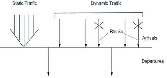
requests may be categorized into static and dynamic.
2.5.1 Static Routing and Wavelength Assignment
With Static RWA, all connection requests known in advance. The traffic demands are
specified regarding source-destination pairs [23]. This pair is chosen for the relatively
long-term requirement and does not change significantly over time. The purpose is to
optimally find the end-to-end routes and assign the wavelength for the traffic demand while
the number of wavelengths is minimized [21].
Figure 2.5: Scenario of Static and Dynamic Traffic in SDM
2.5.2 Dynamic Routing and Wavelength Assignment
For the dynamic RWA, the requests are not known in advance. When a connection
request arrives, a lightpath from the source node to the destination node specified in the
request set up, if possible. This lightpath is torn down after a finite amount of time so that
the resources used by the lightpath are available for future requests for communication. The
objective in dynamic RWA is to set up lightpaths and assign wavelengths in a manner that
minimizes the blocking probability- the ratio of the number of requests for communication
[21].
2.6
Optical Orthogonal Frequency Division Multiplexing
The researchers witnessed a dramatic increase in data traffic which requires more
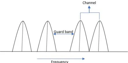
effi-cient and robust data transmission methodology for bandwidth more than 100Gbps. WDM
networks follow fixed bandwidth allocation of each request for communication as shown in
Figure 2.6, thus to address the limitation they introduced Orthogonal Frequency Division
Multiplexing (OFDM) as a modulation technique for optical network [24].
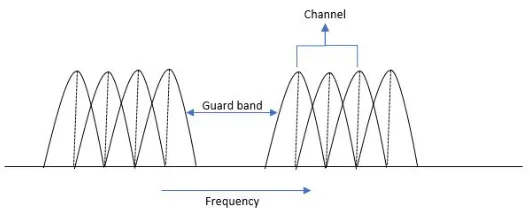
OFDM is a Multi-Carrier Modulation (MCM) scheme that communicates a data stream
dividing it into a number of subcarriers, each carries a comparatively low data rate
sig-nal [24]. The number of subcarriers gets allocated according to the request. More than one
contiguous subcarriers get allocated when a connection demands a capacity more
signifi-cant than a single OFDM subcarrier as shown in Figure 2.7 [24]. The minimum allowed
gap separating two bandwidths using the same fiber in the optical network defines guard
band[24] as shown in Figure 2.6 and 2.7. In this way, only part of available bandwidth on
each fiber is used, as opposed to the WDM technique. OFDM is suitable for
communica-tion which requires more bandwidth due to its nature of elasticity in bandwidth allocacommunica-tion
property which possesses better spectral efficiency and impairment tolerance [24].
Figure 2.7: Spectrum in OFDM
Orthogonality in OFDM: In OFDM technology, subcarriers overlap with each other.
However, the information of one subcarrier does not get overlap with the subcarrier such
that when a subcarrier is at its peak, other subcarriers have zero crossing at that particular
point. Hence, the information is only being read when the subcarrier is at its peak level as
shown in Figure 2.8. It certainly avoids the interference of two signals. Ultimately, the use
of orthogonal subcarriers allows usage of more subcarriers per bandwidth which in turn
increases the spectral efficiency.
2.7
Routing and Spectrum Allocation
In a network, a route and a spectrum have to be allocated to each communication request
which consists of a source for the communication, the destination for the communication
and, on each fiber in the path to accommodate the required number of subcarriers (i.e., equal
to or more than required bandwidth) for the communication. This process of determining
the route and spectrum for the communication request is known as Routing and Spectrum
Allocation (RSA) [2]. The objective of RSA is to efficiently find an appropriate path and
assign a spectrum for the communication request, such that no two requests are allotted
the same bandwidth where one or more edges are being shared. Also, each communication
request should maintain the same bandwidth [25]. The main goal of RSA is to minimize the
number of connections on the network by minimizing the usage of the frequency spectrum.
RSA mainly consists of two constraints:
• Spectrum Continuity Constraint: According to this constraint, the spectrum
assigned to each lightpath must be the same throughout the route. Thus the
starting frequency/bandwidth should be the same for each request from the
source to the destination on all the fibers to be used in the lightpath [26].
• Spectrum Contiguity Constraint: This constraint assures that the subcarriers
allocated are contiguous in the spectrum [26].
2.8
Space Division Multiplexing
The techniques used in optical technology in the telecommunication are Wavelength
Di-vision Multiplexing (WDM), Time DiDi-vision Multiplexing (TDM), Orthogonal Frequency
Division Multiplexing (OFDM) and Polarization Division Multiplexing (PDM). For
approaches with the strategy of exploring the unused dimension, that is space [8].
A rapid increase in popularity and variety of bandwidth-demanding applications resulted
in incremental exhaustion of available spectral resources according to Shannon capacity in
the current networks. Space Division Multiplexing (SDM) approach appears as a promising
solution approach for overcoming the bandwidth limitations. This technology has dragged
attention of researchers due to its superior advantages for optical communication [14]. One
of them being its greater data transmission capacity as it can transfer larger quantity of
information through a single optical fiber making it both cost and time effective.
Space Division Multiplexing uses multi-core fibers or Few-Mode Fibers which increases
capacity and reduces the cost per bit of fiber-optic transmission [27]. The difference from
the other multiplexing schemes and in SDM is, a single fiber is replaced with the multiple
strands and used parallel transmission concept. For instance, consider the following Figure
2.9 where data to be flowing from node 1 to 2, earlier we considered bidirectional edges
for the data flow, whereas for SDM multiple cores (for example, four cores between two
nodes as shown in Figure 2.10) are used to carry data from the source (node 1) to the
destination (node 2). It enables more substantial data transmission using the same resource
simultaneously.
Figure 2.10: One super-channel divided into multiple cores in SDM
2.8.1 Types of Fibers used in SDM
Space Division Multiplexing supports parallel communication of optical channels
trans-mitting through spatial channels in fiber optics medium. Various fiber optic media proposed
for SDM are as follows:
• Single Mode Fiber (SMF): Single fiber optic cable possess a small
diametri-cal core which allows the only single mode of the optidiametri-cal signal to propagate.
Hence, the number of reflections generated as the light passes through the core
decreases, creating the ability and lowering attenuation for the signal to travel
further. Therefore, this cable is appropriate for the long distance and higher
bandwidth [28]. For SDM, a bundle of fibers is achieved with the aggregation
of SMFs. However, it has high deployment cost [14].
Figure 2.11: Cross section of a Single mode fiber
• Multi Core Fiber (MCF):The multi-core fiber involves multiple single mode
comprises of the various structure such as one-ring, dual-ring, linear-array,
two-pitched and hexagonal close-packed structure. This MCF cables, due to
crosstalk between the adjacent cores when the optical signals or lights are
trans-mitted in an overlapping spectrum segment leads to signal impairments [14].
Figure 2.12: Multi core fiber
• Multi mode Fiber or Few-Mode Fiber (MMF/FMF):Multimode fiber optic
cable possess large diametrical core which allows multiple modes of the optical
signal to propagate. Because the number of light reflections created as the light
passes through the core increases, this creates the ability for more data to pass
through at a given time. Due to the high attenuation rate and dispersion with the
fiber, the quality of signal reduces over increasing distance. This fiber cable is
suitable for the short distance, data and audio/video applications in LANs [28].
2.8.2 Ways of realizing SDM Transmission
Space Division Multiplexing allows multi-carrier transmission (i.e., super-channel
trans-mission). The Optical Carriers (OCs) generated or terminated using transceiver devices as
transmitted as a high-capacity super-channel over the network. Each super-channel uses a
modulation format and carries a fraction of aggregated traffic. In SDM, the super channels
are transmitted using Spectral and Spatial Resources (SpRcs). The optical carriers use both
the frequency and spatial domain. There are various models which differ in the grade of
spectral and spatial flexibility used in different scenarios of data transmission. They are as
follows: [14].
• Fixed-grid/Single - This scenario corresponds to the simplest case of a WDM
network with the expansion in the spatial domain as shown in Figure 2.14. The
model has a fixed frequency grid and possesses a single-carrier transmission
where the optical channel cannot be split in the spatial domain.
Figure 2.14: SDM Model: Fixed-grid- Single [14]
• Flex-grid/Single Here in Figure 2.15, the flexibility is introduced in the
spec-tral domain in the Elastic Optical Network (EON) architecture. However, the
super-channels occupy flexibly allocated segment of spectrum, thus only
Figure 2.15: SDM Model: Flex-grid/Single [14]
• Flex-grid/Fixed - In the Figure 2.16, the super-channel uses the spectral and
spatial domain. The optical carriers (OCs) belonging to a super-channel can
be transmitted using the different spatial resources but use the same spectrum
segment. Moreover, the super-channels cannot overlap the spectrum domain.
The model is suitable for MMF/FMF systems. [14].
Figure 2.16: SDM Model: Flex-grid/Fixed [14]
• Flex-grid/Semi-flexible - In this Figure 2.17, the super-channels are further
extended in the spatial domain by the introduction of spatial groups. Here,
SpRcs are divided into some groups and only one super-channel can be carried
through each group within given spectrum window [14].
• Flex-grid/Flexible - In this Figure 2.18, full spectral and spatial flexibility in
forming super-channels is considered. [14]. Although this scenario enables
best resource utilization theoretically, it may lead to fragmentation of spectrum
that is residual of remaining gaps instead of fixed spacing which is generally
not considered for allocation of new requests. Therefore, implementation of
this model is possible but also is challenging from the perspective of efficient
demand allocation.
Figure 2.18: SDM Model: Flex-grid/Flexible [14]
2.9
Optical Reach
When the optical signal travels a long distance through the optical fiber, the quality of the
optical signal starts degrading at a certain distance in the optical fiber. Here, theOptical
Reach is defined as the distance an optical signal can traverse before the signal quality
degenerates to a level that necessitates regeneration [29]. A smaller number of regeneration
required for the longer optical reach of optical signals, and hence less equipment required
thus lower operating costs. To achieve longer optical reach, more expensive equipment such
as amplifiers and transponders are needed. As the optical reach continues to increase, the
cost-benefit provided by reduced regeneration is eventually offset by the more expensive
system equipment [29]. The factors affect the optical reach are the launched power of the
Consider a topology shown in Figure 2.19 the lightpath from node 1 to node 5, the optical
reach of the lightpath is 1400 km.
Figure 2.19: Optical Reach
2.10
Modulation Format
The optical fiber system gives network services at high speed as they have high capacity
transport infrastructure. This system drive for low costs per transmitted bit with high
spec-tral efficiency. The fiber-optic system has the capability to transmitting Tb/s bits over 1000
kilometers. The system can have an attenuation coefficient 0.2db/km for several THz of
bandwidth, exceeding the transmission distance than 10,000 km and having a capacity of
more than 10Tbps. The channel utilization and capacity can be improved using advanced
modulation format. A better performance of Optical fiber can be achieved by using different
modulation formats. In flex-grid networks, the modulation format for every
communica-tion can be chosen independently during the process of the allocacommunica-tion. Distance-adaptive
concepts add new trade-off between optical reach and spectral efficiency [25]. For instance,
of low spectral efficiency. Quadrature Phase Shift Keying (QPSK) provides better spectral
efficiency than BPSK [25]. Moreover, modulation format like 16-Quadrature Amplitude
Modulation (QAM) transmits the same bit rate possessing approximately one-fourth of the
bandwidth of BPSK, however with a significantly shorter optical reach.
For the topology in Figure 2.19 where the length of optical reach is 1400 km, therefore
8-QAM is best suitable modulation format which can be applied to the considered network
topology.
Modulation Format Optical Reach (km) Spectral efficiency (bps/Hz) (Mp)
BPSK 9600 1
QPSK 4800 2
8-QAM 2400 3
16-QAM 1200 4
Table 2.1: Modulation Format
2.11
Literature Review
In [2], the author outlines the Integer Linear Programming (ILP) considering the
possi-bility of disasters in the Data Center (DC) Network. Their work focuses on developing a
path protection scheme to handle communication requests in Data Center (DC) networks
using Elastic Optical Networking (EON) and Space Division Multiplexing (SDM). They
determine a dedicated primary path and backup path for communication as they
concen-trate on fault tolerance, possible allocation of the spectrum using Flex-grid/Fixed SDM
model and measure the cost of the resources required to handle the new request. The
re-search chooses the possible modulation format for data transfer to minimize the number of
subcarriers needed [2]. Their study presents that the blocking probability of the network
subcarriers per core and the number of cores [2].
Krzysztof Walkowiak et al. in [14] presents the Integer Linear Programming (ILP)
streamlining models for SDM flex grid optical systems. The proposed models exhibit
the diverse ways for information transmission through SDM, each described with
differ-ent flexibility in the utilization of Spectral and Spatial Resources (SpRcs). They have
an-alyzed the details of the ILP models depicting the technological aspects of SDM. Their
work focuses on generic ILP formulations that can be utilized to model various versions
of SDM which can lead to the discovery of various methods for using the spatial domain
available in SDM optical network. The paper depicts the types of fiber strands which
can be utilized for SDM optical networks for parallel transmission of optical light
sig-nals and briefly talks about the idea of super-channels. When a high-limit super-channel
is transmitted over the network, it may comprise of some Optical Carriers (OCs), which
get generated or terminated using devices called transceiver, using a modulation format
and transmitting a fraction of the flowing traffic. The OCs in SDM can be transmitted
using both frequency and space domains. Authors have concentrated on channel-based
modeling in this paper and describe a few models through which SDM transmission can
be acknowledged, specifically Fixed-grid/single, grid/single, grid/fixed,
Flex-grid/semi-flexible, Flex-grid/flexible. They additionally formulate three ILP models and
apply it to three SDM situations, the primary being Flex-grid/Flexible. The main aim was
to minimize the overall spectrum usage of the network to provision the demands,
con-sidering all the links and SpRcs. The considered model uses a Flex-grid/Single scenario
when each demand is assigned to at most one SpRc on each connection. Although the
arrangement assessed by explaining this model fulfilled every one of the requirements, it
failed to address one major issue presented by SDM, i.e., Light path-to-Spatial-Resource
(LtoSR) assignment. Their last model examines Flex-grid/Fixed situation when all the
oppor-tunity of exchanging spectral slices freely. They analyzed the optimal solution given by
the thee ILP models and inferred that the initial two did not appear to be scalable when
explained specifically utilizing exact methods so that they might come up with a heuristic
arrangement of it in future.
The paper [25] focuses on a distance-adaptive scenario when a similar connection
de-mand can be transmitted with various modulation formats and is related to multiple
spec-tral efficiencies and optical reach. As spectrum fragmentation degrades the performance
(i.e., blocking probability). In flex-grid networks, the modulation format can be chosen
autonomously for every connection amid the resource allocation process. For instance,
modulations like BPSK, have longer optical reach, however, have low spectral proficiency,
though 16-QAM transmits same information using one-fourth of the bandwidth. The
pa-per describes on the allocation of dynamic connection demands when they are received,
deciding its route, modulation, and the band to be designated through Routing and
Spec-trum Assignment (RSA). Zaragoza et al. review the existing RSA approach in the paper
which apply to heterogeneous flex-grid optical networks, assessing their blocking
probabil-ity averaged among services, their decency in adjusting the blocking probabilities seen by
different functions. The simulation study has been performed to analyze the performance
of two different RSA algorithms namely blocking model and incremental model. In the
paper, the authors compare the network capacity and fairness performances for a set of
previously proposed algorithms, revealing their merits in both dimensions.
In the paper [30] Muhammad et al. examines that for including the capacity limitation
of the networks dependent on Single-Core Fiber (SCF) and for accomplishing far higher
transmission throughput and spectral efficiency. The authors have thought of exploiting
the only available measurement, i.e., space. For allocating of spectrum slices by the traffic
requests in flex-grid networks, the Routing and Wavelength Assignment (RWA) problem is
utilize multi-core fibers for spectrum and core allocation during traffic demands. Because
of the spectrum, non-overlapping constraint in flex-grid different traffic demands with
cur-rent spectrum slices cannot traverse through the same network link. Even though requests
can be routed through a similar connection but different cores if they share some common
spectrum slices [30]. The paper also investigates the Routing, Spectrum and Core
Allo-cation (RSCA) problem for flex-grid optical networks formulates RSCA network planning
problem using ILP. For an RSCA problem, all the traffic requests in the system are known
before, i.e., the requests are static. They give an optimal solution for provisioning the
re-quests through the appropriate allocation of spectrum and core, while effectively using all
the spectrum resources. The optimal solution evaluates the number of spectrum slices
re-quired to serve given traffic demand, and furthermore fulfill all the other constraints, for
ex-ample, inter-core crosstalk (XT) and spectrum overlapping simultaneously [30]. The paper
gives a summary of the crosstalk issue for systems with MCF. For incorporating the
inter-core crosstalk (XT) in the ILP formulation, two different methodologies were proposed.
In the first place, slices with the same spectrum cannot be assigned to different demands
that transmit through neighboring cores unless the crosstalk level at the receiver end is
be-neath a given threshold. The other methodology is to pre-process the crosstalk values for
every path and choose a route with the amount of crosstalk below a given threshold [30].
An adaptable and viable heuristic is proposed for a similar issue. After analysis of the
solutions, they inferred that their proposed ILP demonstrate adaptable for small networks
and low traffic, however, more significant topologies with high traffic requests effective
solutions within the ideal time can be obtained if heuristic approaches are utilized. The
connected heuristic strategy conveys the traffic requests as per the required spectrum and
path. To establish a new request, the spectrum resources are gradually increased after every
iteration until the demands are met in the network. The results conclude that the proposed
time [30].
The paper [13] gives an overview of the most recent advancements and methodologies
concerning flexible optical networking and the observed advantages that spatially
flexi-ble networking approaches can contribute to optical networks. It alludes to the limit of
a network to dynamically modify its resources, such as the modulation format, or optical
bandwidth according to the required bandwidth and transmission characteristics of each
re-quested connection. Klonidis et al. talks regarding the different channel allocation options
over the available fiber dimensions which are its wavelength, bandwidth or space approved
by the latest relevant technology advances and research efforts. Next, the possible
flex-ible networking approaches considering both spectral and spatial network flexibility are
commented on and discussed, identifying their benefits, limitations, and synergies [13].
The author says that the classic SDM approach of placing a spatial demultiplexer is before
a spectral demultiplexer to process and extract the spatially multiplexed data can also be
applied to the spectrally flexible networking systems. The last part focuses on network
de-sign, planning, operation, and control issues, addressing the latest advancements in flexible
optical networking, while also highlighting the primary research directions and required
modifications for the introduction of flexibility in the space dimension [13].
Wang et al. in [31] talk about the Orthogonal Frequency Division Multiplexing (OFDM)
technology empowers the elastic and flexible bandwidth allocation in the SLICE network
[32]. When a user request requires multiple sub-carriers, consecutive sub-carriers in the
spectrum domain are allocated and overlapped without using the spectral gap or the
guard-band frequencies [31]. Similar to RWA in WDM networks, the SLICE network deploys
the routing and spectrum allocation (RSA) process to serve the traffic demands [31]. The
aim of the paper [31] is to consider an optimal solution and propose new methodologies
for the analysis of the number of subcarriers used in a general mesh network. The
optimizations goals. One, minimizing the maximum subcarrier index among all the fibers,
and the second being the minimization of the total allocated sub-carriers over all the fibers,
keeping five constraints in mind, namely, the traffic demand constraint and Sub-carrier
ca-pacity constraint, Spectrum Continuity Constraint, Guard-Carrier Constraint, Sub-carrier
Consecutiveness Constraint [31]. They also analyze the upper and lower bounds for the
maximum subcarrier index in a SLICE network. These methods improve the limits for the
case with predetermined routing knowledge. Also, the simulations presented in [32] review
two other efficient heuristic algorithms, namely the BLSA or the balanced load spectrum
allocation and SPSR or the shortest path with maximum spectrum reuse under different
optimization goals [31].
The problem of optimization and modeling of RSSA has been a subject of several papers.
In [30], [33], [34], ILP formulations of RSSA for SDM network with MCFs are proposed.
Besides, in [30] and [35] some heuristics for XT-aware SDM network planning are
devel-oped. The authors of [36] use a simple k-shortest path and first fit allocation algorithm
to analyze different SDM switching strategies in an off-line network planning scenario.
Similarly, a comparison of SCh allocation schemes in a dynamic SDM network is a
sub-ject of [37]. Moreover, some heuristic algorithms for dynamic lightpath setup are studied
Chapter 3
OPTIMAL RSA FOR SDM OPTICAL NETWORK
UNDER DYNAMIC TRAFFIC
3.1
Introduction to the problem
In recent years, growing demands for the cloud services all over the network, requirement
of the bandwidth is increasing exponentially. To increase the ultra speed for satisfying user
requirements, models of Space Division Multiplexing are in discussion. In a data center
network, a network consists of nodes which comprise of typically computers or data
cen-ter representing either source of data or destination for the data, and edges which represent
fiber links connected to the nodes in the network. A cloud service network contains various
data centers which handle the customer requests regardless of the location of the customer.
Generally, the data centers process a request of a file determined from a user and
commu-nicate the requesting file to the user node. In a robust data communication network, the
data center ensures that the requested file is communicated to the user even if a disaster
occurs. For maintaining the robust DC network, it must ensure that the multiple replicated
data must store in the various data center of the network.
In our problem, we are considering the dynamic traffic scenario where a specific
com-munication scheme is defined in response to each request for comcom-munication. For our
problem, we are not considering the scenario of the disaster of the nodes or links in the
network. Considering a network topology withnnodes in a network,Ebidirectional edges
(fiber links) in a network,Cnumber of cores per fiber, set of data centers in a network S
prede-termined according to requirements of data centers in a topology described in [20]. We
determine a primary communication path using Routing and Wavelength Assignment for
the dynamic traffic. This path is torn down within a finite amount of time. The primary path
allocated is the optimal path amongst the available path for the demanded request. If the
re-quired resources are not available to satisfy the requested bandwidth, then that connection
request is blocked.
3.2
Assumptions
The assumptions made for the resource allocation in a Data Center Network are as
fol-lows:
• The network uses Routing and Wavelength Assignment (RWA) for data
com-munication.
• The network uses flex-grid flexible model for SDM networks.
• The network supports the number of on-going communications on the network
when a new request arrived for transmission. The details of each existing
com-municationQ are known, we have all the information about the available and
used resources to handle the arriving demand.
3.3
The Objective of our Approach
For our algorithm, we consider the set{q1,q2, . . . ,qp}as the set of requests and the set
{S1,S2, . . . ,Sn} as a set of Data centers in a network. Our objective is to determine the optimal path from the data center node to the destination node; the allocation handles the
• The primary communication will be from some node Si, 1≤i≤n, to node Sj, 1≤ j≤n.
• The length of the path used by the primary communication will determine
the optimum path using Routing and Wavelength Assignment, and the path
is recorded for the further arriving requests.
• The detail information regarding path set up during allocation of the
commu-nication is used while tearing down the path in a finite amount of time.
• Allocating the optimal path amongst the available paths which minimize the
number of subcarriers needed to carry out the new communication.
• Measure the cost of the resources used to handle the new request by the sum of
the spectrum bandwidths needed for the new communication.
• Calculating the blocking probability on the basis of the blocked demands in the
network.
3.4
Virtual Node
Considering a data center network, when the data is requested for the communication
the source node is not specified. In other words, only the data is to be retrieved for the
node is specified. Our approach needs to determine which node will act the source node
of the path. This node corresponds to one of the data center nodesSi from the set of the data center nodes{S1,S2, . . . ,Sn}which stores all the information regarding the requested data. To determine which data center will act as a source node, for the primary path, let’s
Figure 3.1. The virtual edges are the unidirectional edges between the virtual node sand
the data center nodesSi, 1≤i≤n.
Figure 3.1: Six node network topology with a virtual node at 0
This virtual nodesdoes not exist as a node in the network. Since all the virtual edges
from this virtual node have length 0, it does not affect the minimum utilization of the
resource (i.e., the subcarrier) constraints. Our approach picks the nearest data center from
the destination and follows the standard network flow algorithm to find a primary path for
the new request from the virtual node sto the destination noden. Generally, ignoring the
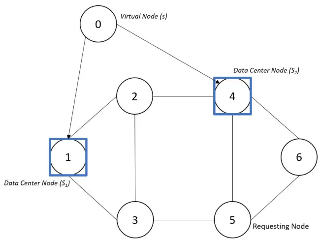
virtual edges, we get the primary path from the data center nodeSito the destination node n.
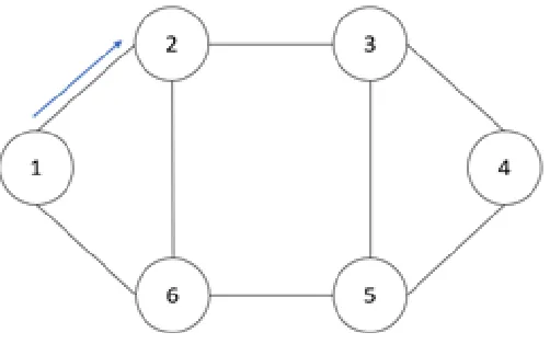
For instance, in Figure 3.1 the topology represents the 6-physical nodes with numbered
1 - 6 and a virtual node assigned number 0. Here, the virtual node is not the part of the
topology but the concept of use of a simple single commodity network flow algorithm. If
the node 1 and 4 are the data center nodes which contain the information regarding all the
requested data to be communicated, the virtual node 0 is connected to the data center node
the Figure 3.1 The ILP choose one source node among node 1 or node 4, to obtain the
optimal path from source node to destination node (i.e., the one which is nearest).
Figure 3.2: Actual path of the communication
Our approach determines the optimal path from the virtual node to the requested node
based on the various factors such as the available spatial and spectrum resources on a fiber
in the path and the distance from the destination node. We get the actual path for
com-munication by ignoring the virtual edges in the path. For example, the requesting node is
5 assuming that it picks the path 0→1→3→5, the actual path for the communication
obtained by ignoring the virtual edges (i.e., 0→1) for the communication is 1→3→5 in
the Figure 3.2.
3.5
Concept of Gaps
Figure 3.2 shows a six-node network with data centers at node 1 and node 4 storing the
requested data, and node 5 is requesting node for the data. The edges 1→3 and 3→5
indicates that the path for primary communication is 1→ 3→ 5. We are using
communication. In SDM networks with multiple core fiber where a single link from the
source node to destination node represents multiple cores. Figure 3.3 shows that the edge
1→3 has divided into multiple cores (4 here) and is now responsible for carrying out the
communication. Similarly, edge 3→5 gets subdivided into four cores for the new request.
Figure 3.3: Available spectrum on cores of Edge 1→3 and Edge 3→5
Figure 3.3 shows the available spectrum on cores of the edge 1→3 and edge 3→5 where
the resource allocation should take place for setting up the new communication request and
where on each core must have an equal number of subcarriers allocation over the spectrum.
The grey rectangular boxes in Figure 3.4 depicts the bandwidth allocation on available
spectrum on edge 1→3 and edge 3→5. The equal bandwidth allocation of spectrum takes
place in all the cores because of the Flex-grid/Flexible model. During resource allocation
process, the Flex-grid/Flexible model chooses the same range of spectrum on both edges
as shown in Figure 3.4. For that, we need to calculate the number of subcarriers available
in each gap of a core on each edge by calculating the difference of ending subcarrier and
starting subcarrier of the gap as shown in the Figure 3.5. For instance in Figure 3.5, the gap
b0013=12 hence the difference will be 12−6+1=7.
Figure 3.4: Bandwidth allocation on available spectrum
Figure 3.5 shows a bundle of fibers, representing an edgei→ j(consider edge 1→3 in
Figure 3.5). The portions with the black boxes of each fiber in this Figure 3.5 are already
assigned to existing ongoing communication. Therefore we cannot use the portions with
the black subcarriers for the new request. Hence we will use unused spectrum (i.e., gaps)
available on edge 1→3 for the new request. Figure 3.5 shows gaps available for allocation
of the spectrum using the Flex-grid/Flexible SDM model.
Figure 3.6: Bandwidth allocation in gaps
If a new communication uses edgei→j, the spectrum allotted to the new communication
must be within the bandwidths shown in Figure 3.6. We call these permissible bandwidths
the gaps on edge(i→ j). The situation described in Figure 3.5, there are 3 gaps available
on core 0, where gap 0 has a starting subcarriera0013=6, ending subcarrierb0013=12 and the
available spectrum is 12−6+1=7. Similarly gap 1 has a starting subcarrier asa1013 =18,
ending subcarrierb1013=21 and available spectrum is 4, and gap 2 has a starting subcarrier
as a2013 =26, ending subcarrier b2013 =30 and available spectrum is 5. Similarly, the gaps
are calculated on all the cores. On the basis of bandwidth required, gaps/spectrum are
been allocated. For example, considering required bandwidth is 15, the most appropriate
spectrum is presented with grey portion in Figure 3.6 because the gaps used in the spectrum
are(4+4+4+4=16). For the other spectrum, the gaps are comparatively bigger which
will decrease the continuous unused subcarriers on cores, may result in blocking the future
communication.
3.6
Notations used in the ILP
In this section we outline the notations used to formulate our proposed algorithm.
N: set of end nodes in the physical network topology.
![Figure 2.3: Wavelength Division Multiplexing [22]](https://thumb-us.123doks.com/thumbv2/123dok_us/1357568.1168587/26.612.153.498.195.475/figure-wavelength-division-multiplexing.webp)
![Figure 2.4: (a) Lightpaths established on physical topology, (b) logical topology corre-sponding to physical topology [23]](https://thumb-us.123doks.com/thumbv2/123dok_us/1357568.1168587/28.612.137.503.151.383/lightpaths-established-physical-topology-topology-sponding-physical-topology.webp)


![Figure 2.16: SDM Model: Flex-grid/Fixed [14]](https://thumb-us.123doks.com/thumbv2/123dok_us/1357568.1168587/37.612.160.487.344.423/figure-sdm-model-flex-grid-fixed.webp)