University of Windsor University of Windsor
Scholarship at UWindsor
Scholarship at UWindsor
Electronic Theses and Dissertations Theses, Dissertations, and Major Papers
10-5-2017
Development of an adaptive cutting device for improved
Development of an adaptive cutting device for improved
crashworthiness performance
crashworthiness performance
Peter SheryUniversity of Windsor
Follow this and additional works at: https://scholar.uwindsor.ca/etd
Recommended Citation Recommended Citation
Shery, Peter, "Development of an adaptive cutting device for improved crashworthiness performance" (2017). Electronic Theses and Dissertations. 7298.
https://scholar.uwindsor.ca/etd/7298
This online database contains the full-text of PhD dissertations and Masters’ theses of University of Windsor students from 1954 forward. These documents are made available for personal study and research purposes only, in accordance with the Canadian Copyright Act and the Creative Commons license—CC BY-NC-ND (Attribution, Non-Commercial, No Derivative Works). Under this license, works must always be attributed to the copyright holder (original author), cannot be used for any commercial purposes, and may not be altered. Any other use would require the permission of the copyright holder. Students may inquire about withdrawing their dissertation and/or thesis from this database. For additional inquiries, please contact the repository administrator via email
Development of an adaptive cutting device for improved crashworthiness performance
By
Peter Shery
A Thesis
Submitted to the Faculty of Graduate Studies
through the Department of Mechanical, Automotive, and Materials Engineering
in Partial Fulfillment of the Requirements for the Degree of Master of Applied Science
at the University of Windsor
Windsor, Ontario, Canada
2017
Development of an adaptive cutting device for improved crashworthiness performance
by
Peter Shery
APPROVED BY:
______________________________________________ V. Stoilov
Department of Mechanical, Automotive, and Materials Engineering
______________________________________________ D. Green
Department of Mechanical, Automotive, and Materials Engineering
______________________________________________ W. Altenhof, Advisor
Department of Mechanical, Automotive, and Materials Engineering
iii
DECLARATION OF CO-AUTHORSHIP / PREVIOUS PUBLICATION
I. Co-Authorship Declaration
I hereby declare that this thesis incorporates material that is result of joint research, as
follows:
Chapter 2 contains material published in an SAE conference paper that I
developed in a collaborative effort. Experiments were performed with Ryan Smith,
Thomas Gruenheid and Professor William Altenhof. Specimens for testing were supplied
by Elmar Beeh and Phillip Strassburger. I certify that I analyzed and interpreted all the
data, and had the role of lead author in preparing and writing the SAE conference paper.
I am aware of the University of Windsor Senate Policy on Authorship and I
certify that I have properly acknowledged the contribution of other researchers to my
thesis, and have obtained written permission from each of the co-author(s) to include the
above material(s) in my thesis.
I certify that, with the above qualification, this thesis, and the research to which it
refers, is the product of my own work.
II. Declaration of Previous Publication
This thesis includes 1 original paper that has been submitted for a conference publication,
as follows:
Thesis Chapter Publication title/full citation Publication status*
Chapter 2
P. Shery, W. Altenhof, R. Smith, E. Beeh, P.
Strassburger, and T. Gruenheid, "Experimental
observations on the mechanical response of
AZ31B magnesium and AA6061-T6 aluminum
extrusions subjected to compression and cutting
modes of deformation," SAE Technical Paper
2017-01-0377, 2017.
Published
I certify that I have obtained a written permission from the copyright owner(s) to
iv
describes work completed during my registration as graduate student at the University of
Windsor.
I declare that, to the best of my knowledge, my thesis does not infringe upon
anyone’s copyright nor violate any proprietary rights and that any ideas, techniques,
quotations, or any other material from the work of other people included in my thesis,
published or otherwise, are fully acknowledged in accordance with the standard
referencing practices. Furthermore, to the extent that I have included copyrighted
material that surpasses the bounds of fair dealing within the meaning of the Canada
Copyright Act, I certify that I have obtained a written permission from the copyright
owner(s) to include such material(s) in my thesis.
I declare that this is a true copy of my thesis, including any final revisions, as
approved by my thesis committee and the Graduate Studies office, and that this thesis has
v
ABSTRACT
A circular cutting device, referred to as the quadrotor, that adaptively changes
configuration to either 4, 6, or 8 equally spaced blades and endures axially cutting
through a 3.175 mm thick AA6061-T6 aluminum extrusion under impact has been
developed to a manufacture-ready stage. The device comprises a pair of uniquely shaped
3-bladed cutters and 4-bladed cutters. Finite element simulations of both cutters during
deployment as well as during dynamic axial cutting were generated to evaluate the device
performance. Virtually, all the parts during the deployment stage of either cutter have
negligible stresses. During cutting, the device was found to endure 36,000 cycles, which
should equate to decades of testing. A simplified apparatus which replicates each cutter
deployment was also constructed to validate the numerical models of each cutter’s
deployment dynamics. As was assumed in the simulations, the neodymium magnet was
necessary to catch the blade upon impact with the end stop. Also, compared to the
simulations, the angular rotation of the 3-bladed cutter and 4-bladed cutter geometries
with respect to time had acceptable validation metrics of 0.78 and 0.70, respectively.
Friction associated with the experimental setup was more significant than expected and
caused both cutters to deploy slightly slower than predicted. Nonetheless, the apparatus
demonstrated a successful deployment of both cutters. The slower cutter had a total
response time of 47 ms, allowing the electronic system that controls the device
configuration to trigger when the impacting entity is still within close range, which is
desirable. Overall, based on the findings of this thesis, the complete quadrotor is worth
vi
DEDICATION
To my parents Robert Shery and Carol Ann Burton, and to my sister Nicole Ann Shery:
vii
ACKNOWLEDGEMENTS
I would first like to thank my advisor Dr. Altenhof for his moral and financial
support throughout my two years at the University of Windsor. At each stage of this
project, he was devoted to guiding me in the best possible direction. His guidance has not
only improved my engineering design skills, but also my redesign skills. Whether
designing a geometric model or a numerical model, I have learned to better recognize the
challenges in every design approach considered, and to devise multiple approaches. I
must also thank him for his excellent tips and teaching of finite element analysis, which I
have discovered through this project to be an interesting and valuable tool that will
greatly benefit my mechanical engineering career.
The technicians at the University of Windsor have also assisted in this project: I
thank Patrick Seguin for constructing the solenoid driver module as well as advising me
on the most economic options for the control system of the adaptive cutting device.
Andrew Jenner, Dean Poublon, and Matt St. Louis also deserve my thanks for machining
the parts for the cutter deployment apparatus as well as providing their insights on the
manufacturing of the device.
Finally, I want to acknowledge the financial support provided by the Natural
Sciences and Engineering Research Council (NSERC), the Ontario Graduate Scholarship
viii
TABLE OF CONTENTS
DECLARATION OF CO-AUTHORSHIP / PREVIOUS PUBLICATION ... iii
ABSTRACT ...v
DEDICATION ... vi
ACKNOWLEDGEMENTS ... vii
NOTE ON UNITS ... xi
LIST OF TABLES ... xii
LIST OF FIGURES ... xiii
LIST OF APPENDICES ... xxi
LIST OF ABBREVIATIONS ... xxii
NOMENCLATURE ... xxiii
1.0 INTRODUCTION ...1
2.0 LITERATURE REVIEW ...4
2.1 Passive Energy Dissipation ...4
2.2 Active Energy Dissipation ...13
2.3 Summary of Literature Review ...17
3.0 RESEARCH OBJECTIVES ...19
4.0 DESIGN ITERATIONS OF THE ADAPTIVE CUTTER ...21
4.1 Preliminary Design Iteration Phase ...21
4.2 Detailed Design Iteration Phase ...25
5.0 FINITE ELEMENT MODELS OF THE QUADROTOR ADAPTIVE CUTTER ...44
5.1 Bolted Connections in the Quadrotor Adaptive Cutter ...44
5.2 Model of the Torsion Spring ...48
5.3 Pre-Cutting Simulations of the Quadrotor Adaptive Cutter ...49
ix
5.3.2 Pre-Cutting in the 6-Blade Configuration ...59
5.3.3 Pre-Cutting in the 8-Blade Configuration ...61
5.4 Axial Cutting Simulations of the Quadrotor Adaptive Cutter...64
6.0 DURABILITY ANALYSIS OF THE QUADROTOR ADAPTIVE CUTTER ...77
6.1 Selected Materials and Fatigue Life of Quadrotor Adaptive Cutter ...78
6.2 Material Sensitivity on Fatigue Life of 4-Bladed Cutter...86
7.0 EXPERIMENTAL TESTING FOR NUMERICAL MODEL VALIDATION ...89
7.1 Experimental Results for the 3-bladed Cutter ...92
7.2 Preface to the Experimental Results for the 4-bladed Cutter ...102
7.3 Experimental Results for the 4-bladed Cutter ...105
7.4 Experimental Kinematics, Dynamics, and Energy Losses For the 3-Bladed Cutter and 4-Bladed Cutter ...115
8.0 TEST PLAN FOR FUTURE CUTTING EXPERIMENTS ...122
9.0 SUMMARY AND CONCLUSIONS ...129
10.0 RECOMMENDATIONS FOR FUTURE WORK ...132
REFERENCES ...135
APPENDIX A: ASSEMBLY DRAWING AND BILL OF MATERIALS FOR QUADROTOR ADAPTIVE CUTTER ...142
APPENDIX B: ENGINEERING PART DRAWINGS FOR QUADROTOR ADAPTIVE CUTTER ...145
APPENDIX C: SOLENOID CONTROL SYSTEM AND ELECTRONIC HARDWARE FOR QUADROTOR ADAPTIVE CUTTER ...160
APPENDIX D: ENGINEERING PART DRAWINGS OF CUTTER DEPLOYMENT APPARATUS ...166
APPENDIX E: FUTURE PROPOSED ADAPTIVE CUTTER DESIGN TO ACHIEVE FASTER RESPONSE TIME ...175
APPENDIX F: FAR-FIELD VIEW OF EXPERIMENTAL SETUP FOR CUTTER DEPLOYMENT APPARATUS ...181
x
APPENDIX H: ADDITIONAL ENGINEERING ANALYSES FOR THE
QUADROTOR ADAPTIVE CUTTER DESIGN ...197
xi
NOTE ON UNITS
Best attempts are made to follow and implement the S.I. system of units. However, in the
minority of cases, U.S. Imperial units are used for appropriate description of bolts and
xii
LIST OF TABLES
Table Page
5.1 Analytical and numerical parameters for each bolted connection of
the quadrotor adaptive cutter. 58
5.2 Critical von Mises stresses in each component of quadrotor
adaptive cutter. 75
6.1 Selected materials for each steel component of quadrotor adaptive
cutter. 86
6.2 Life predictions for different steel grades A, B, C, D, E, and F
assigned to 4-bladed cutter. 88
8.1 Appropriate values of extrusion thickness and velocities (in green)
for each blade number configuration. 124
8.2 Range of impact velocities and distance the dropping impact plate
must be from top of extrusion to activate configuration in time.
Velocities based on 0.75 mm AA6061-T6 extrusion thickness,
59.1 kg crosshead, and approximately 53 mm axial length of cut. 125
8.3 Axial length of cut for each blade configuration and impact
velocity. Velocities based on 0.75 mm AA6061-T6 extrusion
thickness, 59.1 kg crosshead, and approximately 53 mm axial
length of cut. 126
8.4 Range of impact velocities and distance the dropping impact plate
must be from top of extrusion to activate configuration in time.
Velocities based on 3.175 mm AA6061-T6 extrusion thickness,
200 kg crosshead, and approximately 180 mm axial length of cut. 127
8.5 Axial length of cut for each blade configuration and impact
velocity. Velocities based on 3.175 mm AA6061-T6 extrusion
thickness, 200 kg crosshead, and approximately 180 mm axial
xiii
LIST OF FIGURES
Figure Page
2.1 Axial crushing of circular AA6061-T6 aluminum tubes by
progressive folding (left) and global bending (right) [11]. 5
2.2 Typical load/displacement responses of progressive folding and
global bending [11]. 5
2.3 Shards produced by an AZ31B Mg extrusion 3.175 mm thick and
65 mm outer diameter subjected to quasi-static axial crushing [16]. 6
2.4 Load/displacement responses of AZ31B Mg extrusions 3.175 mm
thick and 65 mm outer diameter subjected to quasi-static axial
crushing [16]. 6
2.5 Schematic of axial inversion using conical die [17]. 8
2.6 Load/displacement response of circular tube under compressive
load [18]. 8
2.7 Load/displacement responses of circular aluminum tubes splitting
under compressive load [19]. 9
2.8 Opposing cylindrical indentations (bottom) subjected to axial
crushing [21]. 10
2.9 Load/displacement response of square tubes with bead initiators of
different size vs. no initiator [22]. 10
2.10 Experimental setup of AA6061-T6 extrusion in quasi-static cutting
before test (left) and after test (right) using 5 blades. 11
2.11 Load/displacement responses of quasi-static (left) cutting and
dynamic cutting (right) of AA6061-T6 extrusions using 3, 4, and 5
blades [25]. 12
2.12 Schematic of the deformation modes resulting from the penetration
xiv
2.13 Control of the load/displacement curve by varying thickness of
AA6061-T6 extrusion [31]. 14
2.14 Load/displacement response of frontal crash simulation at 35 km/h.
100 mm lateral offset, with and without release [36]. 16
4.1 Original sketches of the first adaptive cutter design concept. 22
4.2 Original sketches of the second adaptive cutter design concept. 23
4.3 Original sketches of the third adaptive cutter design concept. 24
4.4 (a) CAD model of the first detailed adaptive cutter design.
(b) Section views showing internal mechanics of device in 4-blade
configuration. 26
4.5 CAD model of the rotary cam adaptive cutter with section views of
4-blade configuration along the (a) y-axis. (b) x-axis. 27
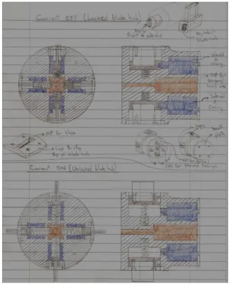
4.6 Original sketches showing the concept of an adaptive cutter with
blades that pivot about bolt shafts like switchblade knives. 29
4.7 CAD model of the rotary switchblade adaptive cutter design. Front
views with cover plate removed showing adaptor position for (b) 4
blades. (c) 6 blades. (d) 8 blades. 31
4.8 Design concept of a switchblade adaptive cutter with blade rotation
from the outside-in and a ring/gear lock. 33
4.9 (a) CAD model of the rotary switchblade cutter design using belt
drive. Front views with cover plate removed showing adaptor
position for (b) 4 blades. (c) 6 blades. (d) 8 blades. 35
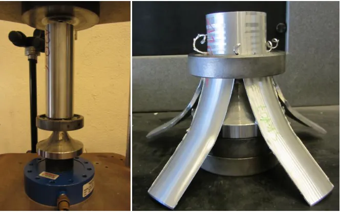
4.10 Comparison between petal flaring of 3.175 mm thick AA6061-T6
extrusions when cutting with (a) 4 blades. (b) 8 blades. 36
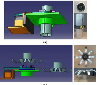
4.11 (a) CAD model of the adaptive cutter using a belt drive and an
elevated support structure. (b) Underside showing petals flaring
xv
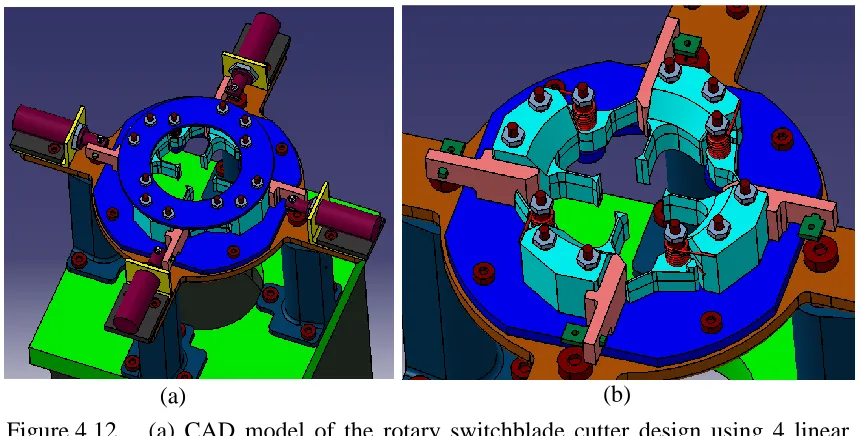
4.12 (a) CAD model of the rotary switchblade cutter design using 4
linear pull-type solenoids. (b) Front cover and solenoids removed
for clarity. 38
4.13 CAD model assembly of the quadrotor adaptive cutter design.
(a) Support legs with Dytran 1210V2 load cells. (b) Elevated
platform. (c) Back cover and solenoid substructure. (d) Full
assembly with front cover removed. (e) Full assembly with front
cover. 40
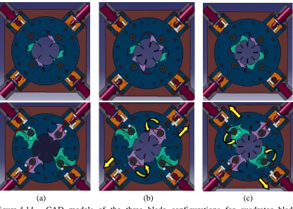
4.14 CAD models of the three blade configurations for quadrotor blade
adaptive cutter design with front cover shown (top) and front cover
removed (bottom): (a) 4 blades. (b) 6 blades. (c) 8 blades. 41
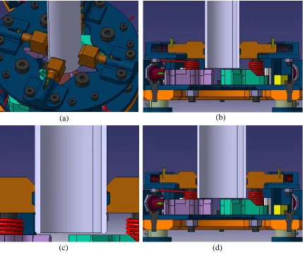
4.15 CAD model of the compression spring loaded 4-jaw chuck.
(a) Isometric view. (b) Section view with 44.45 mm diameter
extrusion. (c) Small positioning groove on outer diameter of
extrusion below bottom jaw teeth. (d) Section view with 63.5 mm
diameter extrusion. 43
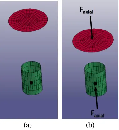
5.1 Rigid shell disk, discrete linear spring, and rigid shell ring for
instantaneous bolt clamping. (a) Spring in tension at time=0.
(b) Spring released after time=0 generating a clamping force on
plates (deformation is exaggerated in image for clarity). 45
5.2 Rigid shell disk, rigid shell ring, and external axial loads for
gradual bolt clamping. (a) No load applied at time=0. (b) Equal and
opposite axial forces applied gradually and held constant after 1 ms
until end of simulation (deformation is exaggerated in image for
clarity). 48
5.3 Mesh of elastic 3-bladed cutter with a rigid loop representing last
coil of torsion spring. (a) Parts used in the model. (b) Bolt hidden to
xvi
5.4 Half model of quadrotor adaptive cutter for the 3 configurations in
the pre-cutting simulations. (a) Isometric view from above.
(b) Top view. 50
5.5 Pre-cutting model of quadrotor in 4-blade configuration (a) von
Mises stresses (kPa). (b) System energies. 53
5.6 M6 bolts through angle plate. (a) von Mises stresses (kPa).
(b) Numerical axial preload at bolt head contact interface. 54
5.7 M10 bolt through elevated platform. (a) von Mises stresses (kPa).
(b) Numerical axial preload at bolt head contact interface. 55
5.8 M8 bolt through back cover. (a) von Mises stresses (kPa).
(b) Numerical axial preload at bolt head contact interface. 55
5.9 ¼ in bolts through L-block. (a) von Mises stresses (kPa).
(b) Numerical axial preload at bolt head contact interface. 56
5.10 M8 bolts through jaw housing. (a) von Mises stresses (kPa).
(b) Numerical axial preload at bolt head contact interface. 56
5.11 ½ in bolts through cutter. (a) von Mises stresses (kPa).
(b) Numerical axial preload at bolt head contact interface. 57
5.12 Pre-cutting model of quadrotor in the 6-blade configuration.
(a) 3-bladed cutter von Mises stresses (kPa). (b) Blade face
contacting magnet von Mises stresses (kPa). (c) System energies. 59
5.13 Impact force between magnet and 3-bladed cutter of quadrotor
(a) Result with a rigid magnet. (b) Result with an elastic magnet. 61
5.14 Pre-cutting model of quadrotor in the 8-blade configuration.
(a) 4-bladed cutter von Mises stresses (kPa). (b) Blade face
contacting magnet von Mises stresses (kPa). (c) System energies. 62
5.15 Impact force between magnet and 4-bladed cutter of quadrotor
xvii
5.16 Cutting models of quadrotor for the 3 configurations. Top views
(left) and up close views of airmesh (right). (a) 4 blades. (b) 6
blades. (c) 8 blades. 66
5.17 Deformation of extrusion during cutting for the 3 configurations of
quadrotor. Front views (left) and top views (right). (a) 4 blades. (b)
6 blades. (c) 8 blades. 69
5.18 Cutting force/time response for the 3 configurations of quadrotor at
blades (left) and at load cell (right). (a) 4 blades. (b) 6 blades. (c) 8
blades. 71
5.19 von Mises stresses (kPa) in quadrotor during cutting in 8-blade
configuration. (a) View from above. (b) View from below. 73
5.20 von Mises stresses (kPa) in cutters and ½ in bolts of quadrotor
during 8 blade cutting (a) bladed cutter. (b) ½ in bolt through
3-bladed cutter. (c) 4-3-bladed cutter. (d) ½ in bolt through 4-3-bladed
cutter. 74
6.1 Sample curves showing fatigue life of steels based on (a)
Amplitude Stress vs. Cycles to Failure [51] (b) Amplitude Strain
vs. Cycles to Failure [52]. 77
6.2 Life contours (cycles to failure) in 3-bladed cutter for 8-blade
cutting condition based on Strain-Life solver from nCode
DesignLife 12.1. 79
6.3 Life contours (cycles to failure) in 4-bladed cutter for 8-blade
cutting condition based on Strain-Life solver from nCode
DesignLife 12.1. 80
6.4 Life contours (cycles to failure) in back cover for 8-blade cutting
condition based on Strain-Life solver from nCode DesignLife 12.1. 80
6.5 Life contours (cycles to failure) in long L-block for 6-blade cutting
xviii
6.6 Life contours (cycles to failure) in short L-block for 6-blade cutting
condition based on Stress-Life solver from nCode DesignLife 12.1. 81
6.7 Life contours (cycles to failure) in support leg for 8-blade cutting
condition based on Stress-Life solver from nCode DesignLife 12.1. 82
6.8 Life contours (cycles to failure) in elevated platform for 8-blade
cutting condition based on Stress-Life solver from nCode
DesignLife 12.1. 82
6.9 Life contours (cycles to failure) in front cover for 8-blade cutting
condition based on Stress-Life solver from nCode DesignLife 12.1. 83
6.10 Life contours (cycles to failure) in jaw housing for 8-blade cutting
condition based on Stress-Life solver from nCode DesignLife 12.1. 83
6.11 Life contours (cycles to failure) in 4-bladed cutter for 6 different
grades of steel A, B, C, D, E, and F subjected to cutting in the
8-blade configuration. Strain-Life solver from nCode Designlife 12.1
used. 87
7.1 CAD model of the cutter deployment apparatus. (a) 3-bladed cutter
assembly (b) 4-bladed cutter assembly. Parts shown in grey are
reused. 90
7.2 Photographs of cutter deployment apparatus. (a) 3-bladed cutter
assembly. (b) 4-bladed cutter assembly. 90
7.3 Distance from face of 12.7 mm laser displacement transducer to
side face of pin for 3-bladed cutter assembly. (a) 8 sample tests. (b)
Envelope for 85 tests. 92
7.4 Distance from face of 25.4 mm laser displacement transducer to
3-bladed cutter. (a) 8 sample tests. (b) Envelope for 70 tests with one
test selected as a representative average. 94
7.5 Distance from face of 101.6 mm laser displacement transducer to
xix
test selected as a representative average. 95
7.6 Impact load from 3-bladed cutter on load cell. (a) 8 sample tests.
(b) Same 8 sample tests zoomed-in between 20 ms and 21.5 ms. 96
7.7 Cumulative error in the load/time response using Test # 1 as the
accepted average for the 3-bladed cutter. 98
7.8 Top view of 3-bladed cutter assembly with selected regions for
image tracking. (a) Start time of deployment. (b) End time of
deployment. 99
7.9 Angular position of the 3-bladed cutter vs. time. (a) ProAnalyst
tracking data. (b) Average experimental response and numerical
simulation. 100
7.10 Cumulative error in the angle/time response using Video # 1 as the
accepted average for the 3-bladed cutter. 101
7.11 Surface condition of aluminum plate. (a) After approximately 100
tests with 3-bladed cutter and 100 tests with 4-bladed cutter. (b)
After manual sanding and polishing. 103
7.12 Distance from face of 12.7 mm laser displacement transducer to
side face of pin for 4-bladed cutter assembly. (a) 8 sample tests. (b)
Envelope for 70 tests. 105
7.13 Distance from face of 101.6 mm laser displacement transducer to
4-bladed cutter. (a) 8 sample tests. (b) Envelope for 70 tests with
one test selected as a representative average. 107
7.14 Impact load from 4-bladed cutter on load cell. (a) 8 sample tests.
(b) Same 8 sample tests zoomed-in to first peak load. (c) Same 8
sample tests zoomed-in to second peak load. 109
7.15 Cumulative error in the load/time response using Test # 1 as the
xx
7.16 Top view of 4-bladed cutter assembly with selected regions for
image tracking. (a) Start time of deployment. (b) End time of
deployment. 112
7.17 Angular position of the 4-bladed cutter vs. time (a) ProAnalyst
tracking data. (b) Average experimental response and numerical
simulation. 113
7.18 Cumulative error in the angle/time response using Video # 1 as the
accepted average for the 4-bladed cutter. 114
7.19 Cubic spline curve fit of angle/time response and its derivatives for
the 3-bladed cutter (a and b) and the 4-bladed cutter (c and d). 116
7.20 Energy and torque vs. angular displacement for both cutters.
xxi
LIST OF APPENDICES
Appendix Page
APPENDIX A: ASSEMBLY DRAWING AND BILL OF MATERIALS FOR
QUADROTOR ADAPTIVE CUTTER 142
APPENDIX B: ENGINEERING PART DRAWINGS OF QUADROTOR
ADAPTIVE CUTTER 145
APPENDIX C: SOLENOID CONTROL SYSTEM AND ELECTRONIC
HARDWARE FOR QUADROTOR ADAPTIVE CUTTER 160
APPENDIX D: ENGINEERING PART DRAWINGS OF CUTTER
DEPLOYMENT APPRATUS 166
APPENDIX E: FUTURE PROPOSED ADAPTIVE CUTTER DESIGN TO
ACHIEVE FASTER RESPONSE TIME 175
APPENDIX F: FAR-FIELD VIEW OF EXPERIMENTAL SETUP FOR
CUTTER DEPLOYMENT APPARATUS 181
APPENDIX G: FINITE ELEMENT SIMULATIONS OF AXIAL CUTTING
FOR THE FIRST ADAPTIVE CUTTER DESIGN 182
APPENDIX H: ADDITIONAL ENGINEERING ANALYSES FOR THE
xxii
LIST OF ABBREVIATIONS
AC Alternating Current
AISI American Iron and Steel Institute
ALE Arbitrary Lagrangian Eulerian
CAD Computer Aided Design
CFE Crush Force Efficiency
CNC Computer Numeric Controlled
CPU Central Processing Unit
DC Direct Current
EDM Electric Discharge Machining
FBD Free Body Diagram
FE Finite Element
GDP Gross Domestic Product
HCF High Cycle Fatigue
IEPE Integrated Electronic Piezoelectric
IHSA Infrastructure Health and Safety Association
LCF Low Cycle Fatigue
MRD Magnetorheological Damper
SAE Society of Automotive Engineers
SEA Specific Energy Absorption
TTL Transistor-Transistor Logic
xxiii
NOMENCLATURE
A Cross-sectional area of bolt shaft
d Diameter of thread portion on bolt
E Modulus of elasticity
Eloss i Instantaneous experimental energy loss in cutter rotation
F Axial force representing tensile preload in bolt
Fc Axial cutting force
Ibolt axis Mass moment of inertia of cutter about axis passing through bolt
K Torque coefficient
KErot i Experimental instantaneous rotational kinetic energy of cutter
k Stiffness of discrete linear spring
kt Torsional stiffness of torsion spring
L Axial length of bolt below head
l Axial length of cut in AA6061-T6 aluminum extrusion
mc Mass of droptower crosshead (carriage)
n Number of tests performed constituting the sample size
Tcutter i Experimental instantaneous inertia torque of cutter
Tfrict i Experimental instantaneous frictional torque
t Wall thickness of the AA6061-T6 aluminum extrusion
Mean response time
V Validation metric
v Velocity of crosshead immediately before impact with extrusion
Zα/2 Z-score for a normally distributed population
αi Experimental instantaneous angular acceleration of cutter
θi Experimental instantaneous angular position of cutter
θpreload Angle of torsion spring at the initial, preloaded position
σ Standard deviation
1
1.0 INTRODUCTION
Unintentional injuries resulting from impact, namely automobile crashes, falling,
and blunt trauma, among other examples, place not only an emotional burden on the lives
of the victims and their families, but an economic burden associated with medical care.
In 2004, injuries classified as unintentional accounted for 81% of all injury costs in
Canada at 16 billion dollars, whereas intentional injuries only accounted for 17% [1].
Two leading causes of unintentional injuries are transport, followed by falling, both of
which are impact-related injuries. Vehicle accidents are the leading cause of death
worldwide in people aged between 15 and 29 and cost governments approximately 3% of
the Gross Domestic Product GDP [2]. In 2014, motor vehicle accidents in the United
States claimed 32,675 lives (i.e. about 1 in every 10,000 people living in the United
States) and 2.34 million injuries [3]. In the same year in Canada, 1,834 deaths and
149,900 injuries resulted from motor vehicle accidents [4], which are also high compared
to the nation’s total population of 36 million. Unintentional injuries from falls are a
frequent occurrence in people aged 65 and over [5]. Among this age group in the United
States, the rate of falls resulting in death has been steadily increasing from 41 to 57
people per 100,000 between 2003 and 2013, with direct medical costs of 34 billion
dollars annually [6]. The top three unintentional injury types are impact-related, namely
motor accidents, falling from scaffolding or ladders, and struck-bys from machinery or
other objects [7]. Struck-bys are also a significant cause of impact injury in the military;
traumatic brain injuries being one of them. Between 2000 and 2015, a total of 327,299
traumatic brain injuries in the U.S. military have been reported, 8,287 of which were
classified as severe or penetrating [8]. The staggering number of deaths and injuries
associated with impacts each year are a harsh reminder that society is in need of energy
dissipating devices that can allow victims to walk away alive and unharmed from
impact-related accidents.
Impacts involving high kinetic energy of the nature mentioned previously often
result in a significant energy transfer to the occupant. For enhanced safety, the devices
that dissipate that energy may need to be sacrificial. For example, automobiles are
designed with sacrificial structures such as crash boxes so that as little energy as possible
2
equipped with restraint devices to prevent from falling. However, the cable itself does not
absorb much of the kinetic energy in the event of a fall, which results in high forces to the
wearer. Audysho [9] had studied a novel material combination, namely stainless steel
braided tubing wrapped around pucks of aluminum foam, which could serve as an
effective sacrificial energy dissipater at the end of a harness cable by significantly
reducing the forces as a falling worker loads the cable axially. To mitigate head and
body strikes, military personnel and athletes in some sports wear padding, which is
typically made of a non-sacrificial material for reusable purposes, but as a result has
limited protection. A material reaches its highest energy dissipating potential when
deformation is beyond its elastic limit and enters the regime of plastic deformation.
The effectiveness of a structure designed to deform plastically under impact is
defined by its crashworthiness. Two important metrics that quantify the crashworthiness
are the specific energy absorption (SEA) and crush force efficiency (CFE). The SEA is
the energy absorption capability of a material per unit mass, and the CFE is the ratio of
the average load to the peak load throughout the entire crushing distance. An ideal
energy dissipating device should not only possess a high SEA and CFE, but also be
stable, repeatable, and have a constant load/displacement curve.
A novel energy dissipating device developed by Altenhof, Jin, and Majumder [10]
involving axial cutting of tubular extrusions has the characteristics of stability,
repeatability, constant load/displacement, and high CFE. However, because the cutting
tools have a fixed number of blades, each tool is optimized for a pre-defined impact
situation. There are two extreme cases that render cutting an ineffective deformation
mechanism: (1) In a high energy impact, if a cutter with few blades was selected, the
SEA of the sacrificial tube may be significantly lower than can be achieved by a
conventional deformation mechanism known as progressive folding. (2) In a low energy
impact, if a cutter with many blades was selected, the kinetic energy is converted into
deformation with a high cutting force and limited cutting distance.
The objective of this thesis is to redesign the cutting tool such that immediately
preceding an impact, the tool can adaptively change for a desired load/displacement
3
the studies by Jin [11], and aims to demonstrate the benefit of controlling the
load/displacement curve. Such a tool would optimize the SEA and still produce a
deformation that is stable and repeatable, with a constant load/displacement response and
4
2.0 LITERATURE REVIEW
The literature review for the purpose of this thesis is divided into two major
categories, namely passive energy dissipation, in section 2.1, and adaptive energy
dissipation, in section 2.2. Within passive energy dissipation, conventional deformation
mechanisms for a ductile metal and brittle metal are first introduced. Deformation
mechanisms that produce constant load/deflection responses, namely axial inversion,
axial splitting, and axial cutting will follow. This last topic will provide a transition to
section 2.2, which reviews literature examining adaptive energy dissipation. Although
this area of research is limited, adaptive energy dissipation was found to be applied in
two broad ways: (1) modifying the geometry of the sacrificial structure, and (2)
incorporating dampers into the structure.
2.1 Passive Energy Dissipation
Structures that must be sacrificed in the event of an impact are often designed
with axially loaded members. A desired mode of deformation under axial loading is
progressive folding [12] because it results in a high specific energy absorption and a high
crush force efficiency. Another possible mode of deformation is global bending, which is
much less effective at absorbing energy as it essentially produces a single fold. After the
initial kink in the member, the load supported by the tube drops steeply and results in a
low SEA and a low CFE, which is an ineffective use of material. The appearance of these
two deformation types are shown in Figure 2.1 [11] and the corresponding
load/displacement responses are shown in Figure 2.2 [11]. Although one may try to
design a structure to fail by progressive folding, a slight off-axis disturbance in the load
can cause the mode of deformation to switch to global bending [13]. Changes in velocity
can also produce the same transition from one mode to the other [14], resulting in
inefficient energy dissipation. Even if progressive folding could be designed to be stable
and repeatable, a disadvantage of this deformation mode is that the load magnitude
oscillates throughout the tube’s crushing distance. An on-board occupant would sense
these oscillations as accelerations acting on their body and may lead to serious injury or
5
Figure 2.1 Axial crushing of circular AA6061-T6 aluminum tubes by
progressive folding (left) and global bending (right) [11].
Figure 2.2 Typical load/displacement responses of progressive folding and
global bending [11].
If one considers a brittle metal rather than a ductile metal subjected to axial
loading, these oscillations would actually amplify because brittle metals can undergo
significant fracturing. For example, AZ31B magnesium extrusions under axial load
revealed sharding [15], which is the formation of sharp mulch-shaped fragments. Shown
in Figure 2.3 [16] is the segmented fracturing mechanism of AZ31B and resulting shards.
In addition to the general oscillatory response, rapid fluctuations of the load/displacement
response were observed as presented in Figure 2.4 [16]. Therefore, an occupant would
sense more violent changes in acceleration with axial loading of a brittle metal than a
6
Figure 2.3 Shards produced by an AZ31B Mg extrusion 3.175 mm thick and 65
mm outer diameter subjected to quasi-static axial crushing [16].
Figure 2.4 Load/displacement responses of AZ31B Mg extrusions 3.175 mm
thick and 65 mm outer diameter subjected to quasi-static axial
crushing [16].
An ideal mode of deformation of the tube should produce no oscillations in force.
A damped response could be achieved if the curve, instead of fluctuating, proceeds
7
exist that can produce such a steady response. Three examples that will be discussed in
this section are axial inversion, axial splitting, and axial cutting.
Referring to the load/displacement responses for progressive folding of
aluminum, presented in Figure 2.2, and axial crushing of magnesium, presented in
Figure 2.4, note that for the same extrusion geometry, the average load for aluminum is
significantly higher than for magnesium. These figures illustrate that different materials
have different energy-absorbing capability. Similarly, one must bear in mind that not all
crashes have the same kinetic energy level. Based only on energy requirement and for a
given extrusion geometry (diameter, thickness, length), aluminum would be a more
suitable material for high energy impacts, whereas magnesium would be a more suitable
material for low energy impacts. However, since the energy from a crash cannot be
anticipated, one cannot select the best energy absorbing material beforehand. Therefore,
an ideal energy absorber should possess two qualities, which are to: (1) damp the load to
a constant level over the entire displacement, and (2) be capable of adaptively adjusting
this load level such that the energy is dissipated over as much of the total extrusion length
as possible.
Axial inversion is a deformation process made possible by axially pushing a
hollow, sacrificial tube which fits over a die having a radius of curvature. As the tube is
pushed through the die, the tube wall flares outward, as depicted in Figure 2.5 [17]. The
load/displacement response is nearly constant, and the average load differs slightly
depending on the die’s radius of curvature according to Figure 2.6 [18]. This adjustability
in the load with changing die radius suggests that axial inversion could potentially be
used as an adaptive energy dissipating mechanism. If one developed a die that could
adaptively adjust its radius prior to impact, the average load could be controlled, and thus
the SEA could be controlled. However, despite having a smooth response, the SEA is far
from that achievable in progressive folding because axial inversion has limited modes of
energy dissipation. The dominant modes are friction between the die and extrusion, and
curling or bending of the tube wall. Additionally, axial inversion is sensitive to the die’s
radius of curvature: a small radius may cause the extrusion to fail by progressive folding,
8
Figure 2.5 Schematic of axial inversion using conical die [17].
Figure 2.6 Load/displacement response of circular tube under compressive load
[18].
Axial splitting is another energy dissipating technique similar to axial inversion in
that a sacrificial extrusion is pushed through a die to force the outer wall to flare outward.
However, in splitting, the extrusion is forced through a cone rather than a die with a
curved radius. If the cone angle is sufficiently large, the wall of the axially pushed
extrusion can divide into separate petals and peel the extrusion like a banana. In addition
to friction and bending, as seen in axial inversion, near-tip tearing of the walls in axial
splitting contributes to the total energy dissipation, making axial splitting a more
9
curling of the petals: a wider cone angle induces more curling than a shallow cone angle,
therefore increasing the total energy absorption. As depicted in Figure 2.7 [19], wider
cone angles produce higher average axial loads, indicating that axial splitting could be
made into an active energy dissipating technique. One could design a cone that adaptively
adjusts its angle prior to impact. However, given the minute increase in axial force using
a cone angle of 75 degrees rather than 45 degrees, splitting appears to have limited
potential for adjusting the SEA. Additionally, the initial tear introduces an undesired peak
load in the force/deflection response.
Figure 2.7 Load/displacement responses of circular aluminum tubes splitting
under compressive load [19].
The initial peak load in splitting can be mitigated by modifying the extrusion
geometry with an intentional stress concentration. Marshal and Nurick [20] provide an in
depth literature review of various crush initiator geometries in tubular structures. In one
example, as shown in Figure 2.8 [21], a cylindrical indentation is made on either side of
the tube which serves to initiate collapse at those locations, stabilize the collapse process,
and reduce the initial load. Tubes with beads of different size were subjected to axial
compression tests, and shown to significantly reduce the initial peak load as depicted in
10
Figure 2.8 Opposing cylindrical indentations (bottom) subjected to axial crushing
[21].
Figure 2.9 Load/displacement response of square tubes with bead initiators of
different size vs. no initiator [22].
A novel energy-dissipating system, patented by Altenhof et al. [10], comprises a
hollow round AA6061-T6 aluminum tube compressed axially against a number of fixed
blades on a specialized tool, effectively cutting through the tube and producing “petalled sidewalls” [23], as shown in Figure 2.10. In addition to other energy dissipation modes,
axial cutting demonstrates the same modes as seen in axial splitting, but with a reduction
in the initial peak load. Under compressive load, the hard AISI 4140 steel cutting tool
subjects the extrusion to stress concentrations in the vicinity of the blades. This localized
11
Figure 2.10 Experimental setup of AA6061-T6 extrusion in quasi-static cutting
before test (left) and after test (right) using 5 blades.
cutting, the force is sustained at a nearly constant level for the length of the cutting
distance, yielding a crush force efficiency (CFE) as high as 96 percent [24]. Numerous
experimental and numerical investigations [11,23-32] have demonstrated that the
force/displacement response is highly predictable and repeatable.
As shown in Figure 2.11 [25], one can see not only the stable load/deflection
response, but the range of average loads achievable when using a different number of
cutting blades. Given a 1.5 mm wall thickness and 44.45 mm outer diameter extrusion, a
range of approximately 13 kN to 19 kN can be achieved when varying the number of
blades from 3 to 5. In addition, the strain-rate insensitivity of AA6061-T6 has
demonstrated that regardless of the strain rate, the average cutting force is nearly identical
if the same number of blades is used. AA6061-T6 is therefore a practical material of
choice for adaptive crash devices: since any crash situation will have an unpredictable
loading rate, an ideal energy absorbing material should not only possess high yield
strength and high ductility, but also little to no strain hardening such that its flow stress
12
Figure 2.11 Load/displacement responses of quasi-static (left) cutting and dynamic
cutting (right) of AA6061-T6 extrusions using 3, 4, and 5 blades [25].
An analytical cutting model developed by Jin and Altenhof [27] predicts the
cutting force for AA6061-T6 extrusions to within 10 % error. The closed form solution of
the steady state cutting force in axial cutting is written as:
Eq. 2.1
The complete nomenclature is described in [27], but in general, the force depends on the
geometry of the extrusion (i.e. Rr, ro, rm, t), material properties (i.e. σ0, μ), geometry of
the blade (i.e. B, T, θ), and the number of blades used (n). Worth noting as well is that the
steady-state cutting force is independent of the extrusion length. This characteristic is
useful for adaptability because it means any arbitrary total length of cut through the
extrusion will only affect the energy absorbed and not the average cutting force.
The energy dissipation modes in axial cutting are well described through Eq. 2.1
as it constitutes a summation of the various energy rates (normalized with velocity to
obtain a unit of force). Embedded in the first term in brackets is a dependence on the
frictional energy. The force would be underestimated by a factor of 3 if friction was not
taken into account. Five terms, each representing a different energy rate, are contained
13
which accounts for approximately 35% of the total energy. The second term is the chip
formation ahead of the cutter blade, which accounts for approximately 25% of the total
energy. The third term is the energy rate of far-field bending also indicated by the stable
flap zone in Figure 2.12 [27]. The fourth term is transient zone flap bending, indicated in
Figure 2.13 by the region on the extrusion located near the tapered face of the blade. The
fifth term is the energy rate by circumferential membrane stretching. The latter three
modes account for approximately 12 to 15 % each of the total energy. Clearly, the
effectiveness of axial cutting is indicated by the additional energy dissipation modes that
are nonexistent in axial splitting or in axial inversion.
Figure 2.12 Schematic of the deformation modes resulting from the penetration of a
single cutter blade through the sidewall of a circular tube [27].
2.2 Active Energy Dissipation
Energy dissipation mechanisms classified as active are a limited area of research
and few publications can be found on this topic in the open literature. In addition, active
energy dissipation does not refer to the electronic systems designed to prevent a vehicle
from frontal or rear collisions, known as crash avoidance systems. These systems have
certainly improved the safety of vehicles [33]. However, many crash events occur too
suddenly to have any foreseeable warning for a crash avoidance system to detect in time
and maneuver the vehicle out of harm’s way. In the event of an unavoidable crash,
vehicles must still be designed to absorb the energy effectively. On one hand, a passive
energy absorber has no control over the load/deflection response once it is mounted in a
14
capable of adjusting the expected load/deflection response either during the process of
deformation or prior to deformation.
The predictability of cutting deformation allows one to adjust the load/deflection
response during deformation by varying the extrusion geometry. For example,
Figure 2.13 [31] shows that a step or even linear profile can be prescribed in the
load/deflection response simply by varying the extrusion thickness along the axial
direction. If a structure required a higher level of energy dissipation at the later stage of
the deformation process, then cutting using an AA6061-T6 extrusion with the geometry
of Figure 2.13(a) demonstrates how that can be achieved. Also note that both of the
load/deflection responses in Figure 2.13(b) nearly overlap, yet were subjected to different
loading rates. Therefore, in one way, this technique of deformation is adaptive because
any speed of impact will result in the same profile. However, in another way, this
technique is not adaptive because the geometry of the extrusion is predefined, which also
predefines the cutting force levels. True adaptability would be to somehow add or remove
material in order to adjust the extrusion thickness while axial cutting deformation is
occurring simultaneously, but such a concept sounds farfetched.
Figure 2.13 Control of the load/displacement curve by varying thickness of
AA6061-T6 extrusion [31].
Bielecki [34] explains that a complete adaptive crashworthiness system must
comprise a sensor to detect the collision in advance, a controller to apply the adaptive
dissipation strategy, and the actively controlled energy dissipaters. A more detailed
15
explanation to adaptive crashworthiness as a concept is described by Holnicki-Szulc and
Knap [35]. The idea is applied to a truss (e.g. the subframe of a train rail car) in which a
damper is mounted in line between each member. The energy absorption of the truss
would be optimized if the deformation is shared over the entire structure rather than
localized in one zone. The authors’ suggest that such a deformation could be achieved in
theory through adaptive crashworthiness. Their approach is to control the yield strength
of each truss member while the structure is plastically deforming simultaneously. The
ideal internal pressure in each cylinder is determined by a complex algorithm and
adjusted continuously: in principle, zones of the truss subjected to higher loads are made
stronger (higher internal pressures), and zones of the truss subjected to lower loads are
made weaker (lower internal pressures) such that the overall deformation is more
uniformly distributed. From a conceptual point of view, the idea is attractive especially
since the load/deflection response of a damper is nearly constant. Unfortunately, one
cannot validate the effectiveness of the concept because it has never been studied
experimentally. Additionally, using dampers to adjust the yield strength of the structure
while it is deforming seems implausible: allowing the truss to deform plastically while
the dampers themselves remain intact and functional is hard to believe. Each member
would need to be controlled to deform purely in the axial direction for the dampers to
function properly. If any member buckles, then surely a damper will also deform or at
least leak fluid and fail to work. Moreover, even if pure axial deformation is achieved, a
large amount of axial space is required to mount the damper. So, the plastic deformation
of the member itself contributes less to the total energy dissipation because less material
is available when a damper is present.
Wagstrom et al. [36] designed an adaptive energy absorbing mechanism in a
vehicle that has a more practical approach. They developed a vehicle chassis where a
portion of the sub-frame could be detached through some deployment mechanism.
Although this work was entirely numerical, the concept seems feasible because the
mechanical system need not be overly complex. They simulated a frontal offset crash,
where the detachable sub-frame is deployed in one case, and not deployed in the other
case. The corresponding numerical force/displacement responses are depicted in
16
response by reducing the peak deceleration level and extending the deformation over a
longer displacement. This work demonstrates a plausible adaptive energy absorbing
system, but unfortunately does not produce the constant load/displacement response that
is desirable.
Figure 2.14 Load/displacement response of frontal crash simulation at 35 km/h,
100 mm lateral offset, with and without release [36].
An adaptive energy absorbing device that does exist in practice is the
magnetorheological damper (MRD) [37]. An MRD is an adaptive energy absorber
because it can actively adjust its damping resistance, which depends on the viscosity of
the fluid inside the cylinder. The fluid contains particles of iron which agglomerate when
subjected to a magnetic field. Thus, the fluid viscosity, and ultimately the damping
resistance, is a function of the strength of the applied magnetic field which controls the
density of iron particle clusters. MRD’s are found mainly in engineering applications
subjected to vibration: examples include vehicle suspension systems [38], rotating
machinery such as washing machines [39], and buildings and bridges for earthquake
mitigation [40]. In all of these cases, the load application is periodic, which is not the
nature of the load application in crashes. MRD’s used in impact situations are not as
common, but they have been investigated. For example, Wereley et al. [41] performed a
theoretical analysis of a dropping payload on an MRD, with the purpose of determining
17
stroke length. The Bingham number (the ratio of the magnetorheological yield force to
the passive damping force) is a measure of the magnetic field strength required to achieve
the optimal damping resistance, where a Bingham number of zero signifies that no
magnetic field is applied. The authors developed a theoretical model that gives the
optimal Bingham number in various drop cases that ensures as much of the available
stroke length is used and the peak force transmitted to the mass is below a threshold
considered a “soft landing”. In a second example, Milecki and Hauke [42] developed a
model of the sudden braking process on an industrial assembly line using an MRD. They
also built an experimental setup consisting of a wagon mass at the top of an inclined ramp
and a shock absorber at the bottom of the ramp. Experimental tests were completed using
a passive shock absorber in one case and a custom MRD with control hardware and
software in another case. The model of the MRD braking force was validated by the
similar force/displacement and force/time responses seen in the experimental tests. The
major finding was that the controlled damper eliminated the sudden peaks in the force
seen in the uncontrolled damper tests, which were the result of the piston bouncing in the
cylinder at the end of the stroke.
2.2 Summary of Literature Review
An ideal load/displacement response with regards to crashworthiness is one that is
steady and predictable. Although progressive folding deformation does have a high
energy absorption capability and some degree of predictability in the force/displacement
response, its high-amplitude oscillations in the force are undesirable. Therefore,
progressive folding is not favourable for adaptive crashworthiness. Energy absorbing
mechanisms that achieve a desirable, constant load/displacement response are axial
inversion, axial splitting, and axial cutting. Inversion was found to be less effective than
splitting or cutting since it has the fewest modes of energy dissipation. Splitting has an
undesired spike in the load/displacement response during initial tearing. Cutting not only
has the largest number of energy dissipation modes of the three mechanisms, but also has
no initial peak load in the response. However, these three mechanisms were only ever
investigated as passive energy absorbers. Papers that discussed adaptive energy
18
predefined structure or used a system of dampers. Predefined structures may produce the
desired profile of the force/displacement response given a set energy level, but cannot
allow for adjustability if energy requirements change. Trusses incorporating dampers
with adjustable internal pressure to adaptively control each member’s yield strength has
been studied at the conceptual level, but lacks credibility as a practical solution. MRD’s
are a practical approach to adaptive energy absorption, but are more suited for vibration
isolation or emergency braking. Under the severe energy dissipation requirements of a
crash, MRD’s would likely deform and be rendered dysfunctional. What would be
necessary for an adaptive crash absorber is that its own plastic deformation possesses the
force/displacement response and adjustability of an MRD.
Considering the three passive energy absorbing mechanisms, cutting seems to
have the most potential for adaptability. Referring back to Figure 2.11, note that the
cutting force in each test is a function of the number of blades used: a higher number of
blades results in a higher cutting force. Since the total cutting displacement is the same in
all tests, then the SEA is controlled by changing the number of blades. Therefore, the
SEA could be adjusted without requiring the geometry of the sacrificial extrusion to
change. Cutting could be made as an adaptive crash absorber because only the tool would
19
3.0 RESEARCH OBJECTIVES
Currently, the cutting tools developed by Altenhof, Jin, and Majumder [10] have a
fixed number of blades. A cutter with a minimum of four blades is required for a stable
cutting failure. From experience, a cutter with more than eight blades has been shown to
circumferentially stretch so significantly that the extrusion binds with the cutting tool.
Therefore, the practical number of blades ranges from four to eight. The scope of this
thesis will involve the design of a single cutting tool that can adjust the number of blades
from four to eight. The tool design will not be one in which the number blades can be
manually configured on a universal hub. Instead, the tool will automatically adjust the
blade number immediately prior to an impact event. Therefore, the design will require a
sensor to detect the impact event sufficiently ahead of time, a controller to trigger the
optimal blade number configuration, and a mechanical deployment system. The tool
should be relatively simple to ensure an economical design. Too complex a design raises
manufacturing costs and reduces the probability that the electromechanical system
deploys reliably, which would render the device impractical. The design must be durable,
meaning that it has to remain functional after being subjected to many tests. In practice,
the tool only needs to work a single time because the crash would likely destroy the
whole device. However, for research purposes, a large number of tests must be performed
to assess the performance of the tool under different loading conditions. In practice, the
tool may be designed for a particular diameter, but in this research, the tool should
accommodate AA6061-T6 extrusions having a range of diameters. The scalability may be
important to assess because different diameters may not result in similar performance.
This thesis will be limited to the design and numerical modeling of this device. However,
the data acquisition hardware and test stand will be integrated into the design so that the
device will be ready for experimental testing by the completion of this thesis, which aims
to achieve the following goals:
1. Conceptualize several design approaches of a tool having cutter configurations
between 4 and 8 blades, before converging on a single best design based on
20
2. Build a finite element (FE) model of each component and virtually assemble the
device.
3. Perform a static stress analysis of the blades to assess whether they can handle the
worst load condition.
4. Develop a rigid body model of the mechanical deployment dynamics to assess the
response time, vibration, and settling time.
5. Develop models of the bolt preloads and the mechanical deployment dynamics
using elastic materials for the entire assembly.
6. Develop numerical models of the cutting process to evaluate the stress on the tool
components, the force/displacement response of the extrusion, and petal
deformation.
7. Compare the axial cutting force obtained numerically with the analytical
steady-state cutting force model developed in [27].
8. Validate the numerical models of the mechanical deployment dynamics by
designing a simplified experimental version of the device and measuring critical
data about its response time and impact load.
9. Design the electronic system used to control the blade deployment mechanism.
10.Prepare the drawings and select all materials and stock parts to have the device
21
4.0 DESIGN ITERATIONS OF THE ADAPTIVE CUTTER
This chapter provides the detailed process behind all of the design iterations.
Section 4.1 is an overview of the preliminary sketches leading to the first detailed design
approach, which possessed elements that would remain throughout nearly all of the
design iterations, namely the use of springs, electro-mechanical actuators, and cutter
configurations with 4, 6, or 8 blades. Section 4.2 dissects all of the detailed computer
aided design (CAD) models considered, including the pros and cons behind each
approach.
4.1 Preliminary Design Iteration Phase
The first design approach considered blades that could displace from a concealed
position to the active cutting position by sliding linearly over rods. The original sketches
of the first cutter design are shown in Figure 4.1. A cross made of cylindrical rods is
welded from the axle (the rod along the centerline axis) to the outer rim, forming a web.
Four holes through which the four blades could deploy to the activated position are
machined in the outer rim. Each custom shaped blade has a cylindrical cavity, which fits
over the rod and presses against a linear compression spring. Coils of copper wire, wound
around the blade hub, has a current flowing through to produce a magnetomotive force to
push the blade against the compression spring and maintain its concealed position. When
the current is shut off, the magnetomotive force is removed and the compression spring
pushes the blade radially outward to its activated position. Four additional fixed blades
(not shown in the drawing) would be integrated on the outside of the ring. Three cutting
configurations are theoretically possible: (1) 4 blades (4 fixed blades on outer rim with
the 4 spring loaded blades concealed), (2) 6 blades (4 fixed blades and 2 opposing spring
loaded blades deployed), and (3) 8 blades (4 fixed blades and the 4 spring loaded blades
deployed). The inner wall of the circular AA6061-T6 extrusion would fit over the outer
ring with some amount of clearance.
A blade protrusion height of at least 10 mm beyond the outer rim would be
needed to accommodate an AA6061-T6 extrusion diameter size of 100 mm (or typically
22
Figure 4.1 Original sketches of the first adaptive cutter design concept.
but achieving this response time requires a spring with very high spring stiffness and long
displacement range, and given the geometry of the frame, a spring this small in coil
diameter and wire diameter would overstress the wire. This cutter frame is therefore not a
practical design and so the copper coil geometry is not even necessary to calculate. A
larger spring contained in a cavity rather than constrained over a rod would render the
spring design more feasible.
The original sketches of the second design conceived are shown in Figure 4.2.
Noting from the front view, an integral cross and rim are formed from a single solid disk
of steel by machining four slices out of the front face. Four cavities are machined on the
outer periphery to fit the linear compression springs and blades/blade hubs. Four
23
sketch). Since more room is available to increase the mean diameter of the spring, it can
achieve the required stiffness and range of displacement without stressing the wire to
failure under static loading. Note the only purpose for the cross shape in the frame is to
provide a shaft over which the copper wire can be wound. The magnetomotive force
necessary to hold the blades in their concealed positions dictate the required copper wire
geometry and current. A simple model of a magnetic circuit can be developed (for one
blade) to determine the viability of the copper windings. Given the geometry of the cutter
design in Figure 4.2, one will find that approximately 200 amp-turns are required, which
24
poses a problem: no practical combination of turns and current level could achieve
200 amp-turns within the confinement of the cutter frame. Due to lack of space, only a
few turns of the copper wire would be possible, and consequently, the supplied current
would need to be very high. These results indicate that using copper windings to provide
the external compressive force against such a stiff spring is not feasible because the
required high current is both dangerous and wasteful of electrical energy.
A more efficient approach to the electrical system would be to have one that is
always off (rather than always on as is the case in Figure 4.2) and only turn on when the