P a g e | 514
Fault Detection and Correction in Using Shortest Path in Wireless Sensor Networks Mamta & Sajjan Singh
Abstract—
Wireless sensor network is a self-organized network that consists of a large number of low-cost and low-powered sensor devices, called sensor nodes. Recent advances in wireless sensor networks have resulted in a unique capability to remotely sense the environment. These systems are often deployed in remote or hard-to reach areas. Hence, it is critical that such networks operate unattended for long durations. Unlike the cellular networks and ad hoc networks where energy has no limits in base stations or batteries can be replaced as needed, nodes in sensor networks have very limited energy and their batteries cannot usually be recharged or replaced due to hostile environments. Therefore, extending network lifetime through the efficient use of energy has been a key issue in the development of wireless sensor networks. In distributed fault detection (DFD) scheme for wireless sensor networks the status of each sensor node to be either good or faulty is based on the neighboring nodes, but in the DFD algorithm [1], when the sensor fault probability increases the fault detection accuracy decreases and the false alarm rate increases rapidly. In this paper an improved DFD scheme is proposed to detect intermittently faulty sensor nodes and to stringent power budget during fault diagnosis process on sensor nodes in wireless sensor network. Simulation results
demonstrates that the improved DFD scheme reduce energy consumption in comparison with previous algorithm. The proposed mechanism is implemented with MATLAB.
Index Terms—
Distributed Fault Detection, Fault Diagnosis,
Self-Managing Fault Management
Mechanism, Wireless Sensor Networks
INTRODUCTION
Wireless sensor network (WSN) is widely considered as one of the most important technologies for the twenty-first century [1]. In the past decades, it has received tremendous attention from both academia and industry all over the world. A WSN typically consists of a large number of
low-cost, low-power, and multifunctional
wireless sensor nodes, with sensing, wireless
communications and computation
capabilities. Many researchers have been working towards fault detection in WSNs. However, the limited ability of individual sensor nodes and the tremendous scale of a sensor network make detecting failures and
ensuring network availability more
difficultly. One reason behind the growing popularity of wireless sensors is that they can work in remote areas without manual intervention. All the user needs to do is to gather the data sent by the sensors, and with
Fault Detection and Correction in Using
Shortest Path in Wireless Sensor Networks
Mamta1 & Sajjan Singh2
1 M.tech, Department of ECE, BRCM-CET,Bahal,Haryana, India.
2 Assistant Professor, Department of ECE, BRCM-CET,Bahal,Haryana, India.
certain analysis extract meaningful
information from them. Usually sensor applications involve many sensors deployed together. These sensors form a network and collaborate with each other to gather data and send it to the base station. The base station acts as the control center where the data from the sensors are gathered for further analysis and processing. In a nutshell, a wireless sensor network (WSN) is a wireless network consisting of spatially distributed nodes which use sensors to monitor physical or environmental conditions. These nodes combine with routers and gateways to create a WSN system. The WSN is made of nodes from a few to several hundred, where each node is connected to one or several sensors. The basic components of a node are:
Sensor and actuator - an interface to the physical world designed to sense the environmental parameters like pressure and temperature.
Controller - is to control different modes of operation for processing of data
Memory - storage for programming data. Communication - a device like antenna for sending and receiving data over a wireless channel.
Power Supply- supply of energy for smooth operation of a node like battery.
Fig. 1: A Wireless Sensor Node
In this approach, the message of updating the node residual battery is applied to track the existence of sensor nodes. A cell manager employs the self-detection approach and regularly monitors its residual energy status. All sensor nodes start with the same residual
energy. After going through various
transmissions, the node energy decreases. If the node energy becomes less than or equal to 20% of battery life, the node is ranked as low energy node and becomes liable to put to sleep. If the node energy is greater or equal to 50% of the battery life, it is ranked as high and becomes the promising candidate for the cell manager. Thus, if a cell manager residual energy becomes less than or equal to 20% of battery life, it then triggers the alarm and notifies its cell members and the group manager of its low energy status and appoints a new cell manager to replace it
II. FAULT DIAGNOSIS
P a g e | 516
Fault Detection and Correction in Using Shortest Path in Wireless Sensor Networks Mamta & Sajjan Singh towards the potential failure of sensor nodes.
To efficiently detect the node sudden death, our fault management system employed an active detection mode. In this approach, the message of updating the node residual battery is applied to track the existence of sensor nodes[7]. In active detection, cell manager asks its cell members on regular basis to send their updates. Such as the cell manager sends “get” messages to the associated common nodes on regular basis and in return nodes send their updates. This is called in-cell update cycle. The update_msg consists of node ID, energy and location information. As shown in figure, exchange of update messages takes place between cell manager and its cell members. If the cell manager does not receive an update from any node then it sends an instant message to the node acquiring about its status .If cell manager does not receive the acknowledgement in a given time, it then declares the node faulty and passes this information to the remaining nodes in the cell. Cell managers only concentrate on its cell members and only inform the group manager for further assistant if the network performance of its small region has been in a critical level. Every cell manager sends health status information to its group manager. This is called out-cell update cycle and are less frequent than in-cell update cycle. If a group manager does not hear from a particular cell manager during out-cell update cycle, it then sends a quick reminder to the cell manager and enquires about its status. If the group manager does not hear from the same cell manager again during second update cycle, it then declares the cell manager faulty and informs its cell members. This approach is used to detect the suddenly death of the cell manager. Group manager also monitor its health status regularly and respond when its residual energy drops below the threshold value. It notifies its cell members and neighboring group managers of
its low energy status and an indication to appoint a new group manager. Sudden death of a group manager can be detected by the base station. If the bases station does not receive any traffic from a particular group manager, it then consults the group manager and asks for its current status. If the base
station does not receive any
acknowledgement, it then considers the group manager faulty (sudden death) and propagates this information to its cell managers. The base station primarily focuses on the existence of the group managers from their sudden death. Meanwhile, the group managers and cell managers take most parts in passive and active detection in the network.
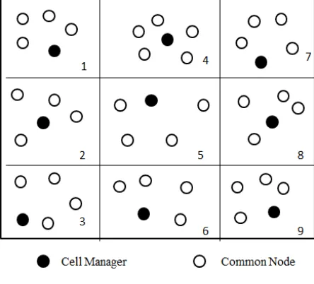
Fig. 2: Virtual Grid of Nodes
of battery life), it then sends a message to its
cell members including secondary cell manager. It also informs its group manager of its residual energy status and about the candidate secondary cell manager. This is an indication for secondary cell manager to stand up as a new cell manager and the existing cell manager becomes common node and goes to a low computational mode. Common nodes will automatically start treating the secondary cell manager as their new cell manager and the new cell manager upon receiving updates from its cell members; choose a new secondary cell
manager [5]. The failure recovery
mechanisms are performed locally by each cell. In Figure let us assume that cell 1 cell manager is failing due to energy depletion and node 3 is chosen as secondary cell manager. Cell manager will send a message to node 1, 2, 3 and 4 and this will initiate the recovery mechanism by invoking node 3 to stand up as a new cell manager.
III. SELF-MANAGING FAULT MANAGEMENT MECHANISM FOR
WSN
We will assume a scenario on sensor nodes. Our aim is to transfer information from one node to another. But this path should overcome all the faults in between. A new technique is introduced for detecting faulty nodes and rerouting the path to get the shortest possible path from sender to receiver which is fault free. In this approach a new fault management mechanism was proposed to deal with fault detection. It proposes a hierarchical structure to properly distribute fault management tasks among sensor nodes by heavily introducing more self-managing functions. The proposed failure detection algorithms have been compared with some existing related algorithm and proven to be more energy efficient. Short-path algorithms generally have polynomial complexity and
generally only produce a single path between a source and destination. In shortest path routing, the topology network is represented using a directed weighted graph. The nodes in the graph represent switching elements and the directed arcs in the graph represent communication links between switching elements. Each arc has a weight that represents the cost of sending a packet between two nodes in a particular direction. This cost is generally a positive value that can inculcates such factors as delay, throughput, and error rate, monetary cost etc [7]. A path between two nodes may go through several intermediary nodes and arc. The objective in shortest path routing is to find a path between two nodes that has the smallest total cost, where the total cost of a path is the sum of the arc costs in that path. Shortest-path algorithms can be divided into two classes: distance vector and link state. Distance vector
algorithms are based on dynamic
programming models and can be
implemented in a distributed, asynchronous framework using local cost estimates. The basic link state method is Dijkstra’s algorithm.[10] The Dijkstra’s algorithm builds the local positions and routings of the estimated sensors for applications that require absolute coordinates of nodes, waiting until large number sensor nodes has formed before transforming to absolute coordinates may be a poor choice. Using the method described here, Position estimation using the shortest path method between source node and destination node with low cost in wireless sensor networks that compute absolute coordinates of individual nodes or
sub networks independently can be
P a g e | 518
Fault Detection and Correction in Using Shortest Path in Wireless Sensor Networks Mamta & Sajjan Singh In addition, it also reduces the response delay
of the management system towards the potential failure of sensor nodes. To efficiently detect the node sudden death, our fault management system employed an active detection mode. In this approach, the message of updating the node residual battery is applied to track the existence of sensor nodes. Here we consider three scenarios- First scenario is scenario without errors second is scenario with errors and last in which path hopping is to be done. These nodes are deployed over area randomly. A new technique is introduced for detecting faulty nodes and rerouting the path to get the shortest possible path from sender to receiver .We also consider energy consumption and delay cases in further simulation part. These nodes are capable of sending, receiving and processing to detect the faulty nodes. So there is methodology for this complete process involved in this. Because a large amount of sensors are deployed into the interested area to form a wireless network, this condition can be easily obtained. We assume that sensors are randomly deployed in the interested area which is very dense and all the sensors have a common transmission range [12]. Each sensor node is able to locate its neighbors within its transmission range via a broadcast acknowledge protocol. To obtain this, some steps are involved which are following as:
Fig. 3: Self-Managing Fault Management Mechanism
The dark circles in the figure represent faulty sensors and the gray circles are good sensors. There might be a failure occurring in a certain area as illustrated in the figure. All sensors in this area go out of service.
As we are depending on majority voting
among the sensors, we assume that each sensor node has at least 3 neighboring nodes. Because a large amount of sensors are deployed into the interested area to form a wireless network, this condition can be easily obtained. Faults can occur at different levels of the sensor network,[6] such as system software, hardware, physical layer, and middleware. In this mechanism, we focus on hardware level faults by assuming the power supply infrastructure. Sensor nodes are still capable of receiving, sending, and processing when they are faulty in the algorithm.
IV. SIMULATION AND RESULTS
o In this approach a total of 3 scenarios
will be implemented the one with no faulty nodes (ideal situation)
o the one where information will stop
when a faulty nodes occur (faulty situation),and
o the one where faults will be detected
and accordingly shortest path will be made(Proposed work)
The proposed mechanism was implemented with MATLAB. The evaluation results should demonstrate the ability of the mechanism to identify faulty nodes anciently and with limited overheads an example simulation scenario composed of total 100 sensor nodes which are randomly deployed.
Fig. 5: Ideal Placement Of The 100 Sensor Nodes
In this we have taken number of nodes deployed in area represented as in above figure.
Fig. 6: Faults Detected In the Scenario In above figure faulty nodes are represented by dark colour
P a g e | 520
Fault Detection and Correction in Using Shortest Path in Wireless Sensor Networks Mamta & Sajjan Singh Fig. 7: Scenario 1: No Errors
This is the ideal scenario. Here, we assume that there are no faulty nodes. All the nodes are authentic and fault free. Information is securely transferred from sender to the receiver. We have selected the shortest path from sender to receiver.
Fig. 8: Scenario 2: With Errors This is scenario in which errors are also considered.
Fig.9: Scenario 3: Path Hopping This is the scenario when the sender finds more than 1 route to the receiver. And even after occurrence of a faulty node, the information loss does not intervenes in the route formation. The route is still completed even after a faulty node occurs. This scenario is meant to show the path hopping between sender and receiver. Information can be transferred from more than 1 route also[9].
This is the final scenario. Here, the faults are
detected and the route will change accordingly. The system will find the shortest path between sender and receiver despite of fault occurrence.
Fig. 11: Comparison between No. Of Nodes And Energy Distribution
In this nodes showing various energy distributions are shown. In path hopping there are multiple path involved , the paths having different nodes energy distribution. The figure shows the delivery of packets at nodes. There are different packet delivery ratios.
Fig. 12 : Packet delivery ratio
P a g e | 522
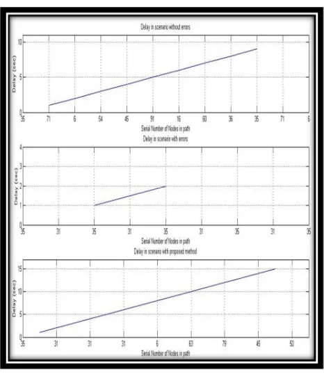
Fault Detection and Correction in Using Shortest Path in Wireless Sensor Networks Mamta & Sajjan Singh In this various delay are considered at
various nodes. These are three scenarios.
V. CONCLUSION AND FUTURE SCOPE
In the Distributed Fault Detection (DFD), there are various algorithm to determine the faulty nodes. We assume the case of power failure as there is no recovery techniques in those area. Therefore we have to change the direction of information when transmitted from a Sender Node to the Receiver Node. This paper has presented a new strategy for power control in WSNs where operational longevity is an issue. As the deployment of Thousand Numbers of Sensor Nodes in Area needs Energy Performance. The new approach provides a methodology for the Retracing of Optimal Path with an Energy Efficiency and Accuracy[1]. This assessment becomes the power performance booster
among the previous workout as it
automatically determines the shortest path after path hopping is traced A self Management approach links the sensor nodes from the source node to the destination node with in a shortest path and shows distributed accuracy. It is estimated that by the year 2020 more than 100 billion wireless sensors will be deployed for applications as diverse as
environmental monitoring, agricultural
monitoring, machine health monitoring, surveillance, and medical monitoring.[11-13] These networks, which connect the physical world with the digital world, provide us with a richer understanding of our environment and with the ability to more accurately control our surroundings. However, there are many challenges thatmust be addressed before the full potential of these networks are realized. Wireless sensor networks must be reliable and scalable to support large numbers of unattended wireless sensors; they must last for extended periods of time using limited
battery power; they must be secure against outside attacks on the network and on data fidelity; they must be accurate in providing required information while performing in-network processing to reduce data load; and they must interface with existing networks.
REFERENCES
[1] Jinran Chen, Shubha Kher And Arun Somani. Distributed Fault
Detection Of Wireless Sensor
Networks, Dependable Computing And Networking Labiowa State
University ames,Iowa
.Pages75-84,Computer Network,2006.
[2] A.A. Abbasi, M. Younis, “A Survey
On Clustering Algorithms For
Wireless Sensor Networks”,
Computer Communications, Vol. 30, Issue 14, Vol. 15, Pp. 2826-2841, October 2007.
[3] N. Vlajic, D. Xia, “Wireless Sensor Networks: To Cluster Or Not To Cluster”, International Symposium On A World Of Wireless, Mobile
And Multimea
Networks(Wowmom06), Pp. 258-268, July 2006.
[4] Benahmed Khelifa1, H. Haffaf ,
Merabti Madjid, And David
Llewellyn-Jones,” Monitoring
Connectivity In Wireless Sensor Networks”, Vol. 2, No. 2, June, 2009 [5] B. Krishnamachari And S. Iyengar. Distributed Bayesian Algorithms For
Fault-Tolerant Event Region
Detection In Wireless Sensor Networks. Ieee Transactions On Computers, 53(3):241–250, March 2004.
[6] M. Yu, H. Mokhtar, And M. Merabti, "A Survey On Fault Management In
Wireless Sensor Network,"
Postgraduate Symposium On The
Convergence Of
Telecommunications,Networking And Broadcasting Liverpool, Uk, 2007.
[7] S. Marti, T. J. Giuli, K.Lai, And M.
Baker, "Mitigating Routing
Misbehaviour In Mobile Ad Hoc Networks," In Acm Mobicom, 2000, Pp. 255-265.
[8] F. Koushanfar, M. Potkonjak, And A. Sangiovannivincentelli, "Fault Tolerance Techniques In Wireless Ad-Hoc Sensor Networks," Uc Berkeley Technical Reports 2002. [9] W. L. Lee, A. Datta, And R.
Cardell-Oliver, "Winms: Wireless Sensor Network-Management System, An Adaptive Policy-Based Management For Wireless Sensor Networks," School Of International Journal Of
Wireless & Mobile Networks
(Ijwmn) Vol.2, No.4, November 2010.
[10] Http://En.Wikipedia.Org
[11] Chee-Yee Chong, Member,
Ieee And Srikanta P. Kumar, Senior Member, Ieee “Sensor Networks:
Evolution, Opportunities,And
Challenges”, Proceedings Of The Ieee, Vol. 91, No. 8, August 2003.
[12] A.Nippun Kumaar, Kiran.G,
Sudarshan Tsb,” Intelligent Lighting
System Using Wireless Sensor
Networks” Vol.1, No.4, December 2010
[13] Zahra Rezaei , Shima
![Fig. 4: Sensor nodes randomly deployed over an area[10]](https://thumb-us.123doks.com/thumbv2/123dok_us/7834393.1298229/5.595.321.543.118.382/fig-sensor-nodes-randomly-deployed-area.webp)