A Solution to Harmonics Generation in Multi-
Level Inverters using Carrier Based Phase
Shift Pulse Width Modulation
Max Savio1, K. Jayavelu2, Dr. C. Rajesh Kumar3
Assistant Professor, Dept. of EEE, Jeppiaar Institute of Technology, Tamilnadu, India1.2
Associate Professor, Dept. of EEE, Jeppiaar Institute of Technology, Tamilnadu, India3
ABSTRACT: Multilevel inverters are suitable for high voltage & high power application due to their ability to synthesize desired output voltage with reduced total harmonic distortion (THD). This paper is focused on cascaded MLI using two unequal dc sources in order to produce a nine-level output. The proposed topology reduces the number of dc sources, switches and losses. Carrier based phase shifted PWM technique is implemented to generate switching signals and to improve the performance of output voltage in cascaded multilevel inverter (CMLI). A nine-level cascaded MLI system for 3ϕ induction motor drive is also presented in this paper. A detailed study of the technique was carried out through MATLAB/SIMULINK for THD.
KEYWORDS: Asymmetric Cascaded Multilevel Inverter (ACMLI); Switching Loss; Total Harmonic Distortion (THD).
I.INTRODUCTION
Function of a multilevel inverter is to synthesize a desired staircase output waveform from several levels of dc input voltages that can be batteries, fuel cells, etc [1].The topologies of multilevel inverter have several advantages such as lower total harmonic distortion (THD), good electromagnetic compatibility, low switching losses, high capability to operate at high voltage and lower voltage stress on semiconductor device [2]. There are three topologies for multilevel inverters: Diode- clamped, flying capacitor and cascaded H-bridge [1]. The proposed topology is the cascaded H-bridge inverter which significantly reduces the switches and the harmonic content as the number of voltage levels increases. It requires two unequal dc sources for producing a nine-level output [2]. Normally, each phase of a cascaded multilevel inverter requires “n” dc sources for 2n+1 level. The cascaded MLI is favorable for high power applications due to its modular structure, because it does not require extra clamping diodes and/or voltage balancing capacitors, and the problem of voltage unbalance is eliminated by reducing the number of dc sources [17].
Multilevel inverters are commonly modulated by using carrier based pulse width modulation techniques such as carrier based phase-shifted modulation and carrier based level-shifted modulation. Among them Carrier based Phase shift PWM (PS-PWM) have been proposed in order to reduce the harmonics at the output and to enhance the performance of the inverter. Carrier based Pulse Width Modulation (CPWM) works with a constant carrier frequency not synchronized with fundamental stator frequency which gives an optimal utilization of switching frequency. However, carrier based level-shifted modulation technique produces the best harmonic performance than the carrier based phase-shifted modulation technique [10,13]. But it is having apparent disadvantages of unequal device switching frequency and unequal device conduction periods. This is undesirable for high power applications. So the proposed method has the following advantages of equal device switching frequency and even power distribution, which is suitable for high power application [11].
the inverter were evaluated by observing the characteristics of stator current, rotor speed, torque and stator flux from the simulated Induction motor model.
II.NINE - LEVEL ASYMMETRIC CASCADED MULTILEVEL INVERTER
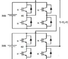
The nine-level cascaded multilevel inverter consists of two H-Bridges. The first H-Bridge H1 consists of dc source 3Vdc ,
whereas the second H-Bridge H2 consists of dc source 1Vdc as shown in Fig.1. Each dc source is connected to a three phase inverter.
Each inverter level can generate three different voltage outputs, +Vdc, 0, and –Vdc by different combinations of the four switches S1,
S2 , S3and S4. When S1 and S4 are on, the output is Vdc, when S2 and S3are on, the output is –Vdc, when either pair S1 and S2 or S3and
S4 are on, the output is 0 [5]. The output voltage H1 can be made equal to −3Vdc, 0, or 3Vdc, while similarly the output voltage of H2
can be made equal to −Vdc, 0, or Vdc by opening and closing its switches appropriately. Therefore, the output voltage of the inverter
can have the values −4Vdc, −3Vdc, −2Vdc, −Vdc, 0, 4Vdc, 3Vdc, 2Vdc, Vdc, can be designed, as shown in Fig. 4. The output voltage of the first H-bridge is denoted byV1 and the second H-bridge is denoted by V2. The output voltage is V=V1+V2 [1]. Figs. 2–
4 show the individual bridge outputs and final nine-level output. Table-I shows the conduction sequence of each switch in asymmetric nine-level inverter. Fig.1 shows the Cascaded MLI with unequal dc sources.
Fig.1. Cascaded MLI with unequal dc sources
Fig.2 shows the Output voltage for First bridge of MLI and fig 3 shows the output voltage of the Second bridge of MLI. Fig.4 shows the Output voltage of Nine-level Asymmetric MLI.
TABLE I. Switching States Of Cascaded MLI
Voltage S1 S2 S3 S4 S5 S6 S7 S8
4Vdc On Off Off On On Off Off On
3Vdc On Off Off On On On Off Off 2Vdc On Off Off On Off On On Off
1Vdc On On Off Off On Off Off On -1Vdc Off Off On On Off On On Off -2Vdc Off On On Off On Off Off On -3Vdc Off On On Off Off Off On On -4Vdc Off On On Off Off On On Off
III. CARRIER BASED PHASE SHIFT PWM TECHNIQUE
Reduction of harmonics strongly depends on the inverter performance with any modulation strategy. The multicarrier sinusoidal pulse width modulation employs N-1 carriers for producing N level output. The modulation control strategies that are proposed under Multicarrier sinusoidal pulse width modulations are carrier phase disposition method and carrier phase shift modulation. The carrier phase shift modulation technique is preferred because the stresses on the switches are equally distributed compared to carrier phase disposition method particularly in producing the upper and lower levels [6-8].
The width of each pulse is varied in proportion to the amplitude of a sine wave evaluated at the centre of the same pulse. The gating signals are generated by comparing a sinusoidal reference signal with a triangular carrier wave of frequency fc. The frequency of reference signals fr, determines the inverter output frequency and its peak amplitude Ar, controls the modulation index M, and rms output voltage Vo. The number of pulses per half cycle depends on carrier frequency [10]. The phase-shift PWM modulation technique have been used to generate a phase-voltage with m levels, this strategy uses (m–1) carriers with the same amplitude, but sinusoidal reference signal is phase shifted with 120º among themselves [13]. Therefore, for a nine-level inverter, this strategy uses eight carriers. The reference and carrier waveforms for phase shift PWM technique is shown in Fig.5.Fig.5 shows the Phase shifted carrier pulse width modulation.
Fig. 5. Phase shifted carrier pulse width modulation
IV. SIMULATION RESULTS
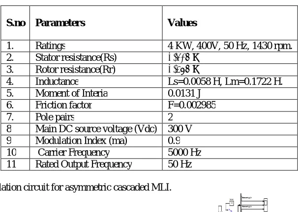
TABLE II. MOTOR SPECIFICATIONS
S.no Parameters Values
1. Ratings 4 KW, 400V, 50 Hz, 1430 rpm. 2. Stator resistance(Rs) 1.405 Ω
3. Rotor resistance(Rr) 1.395 Ω
4. Inductance Ls=0.0058 H, Lm=0.1722 H. 5. Moment of Interia 0.0131 J
6. Friction factor F=0.002985
7. Pole pairs 2
8 Main DC source voltage (Vdc) 300 V 9 Modulation Index (ma) 0.9 10 Carrier Frequency 5000 Hz 11 Rated Output Frequency 50 Hz
Fig.6 shows the Simulation circuit for asymmetric cascaded MLI.
Fig 6. Carrier based Phase shifted three phase nine level Cascaded MLI
Fig.7 shows the phase voltage of asymmetric cascaded MLI and Fig.8 show the line-line voltage for asymmetric cascaded MLI.
Fig.9 shows the Stator current for 3ϕ Induction motor.
Fig. 9. Stator current of 3ϕ Induction motor.
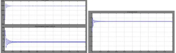
Fig.10 shows the Rotor speed & Electromagnetic Torque for 3ϕ Induction motor. The rotor speed is always less than synchronous speed. Therefore this machines is called as Asynchronous machine. The starting torque of aninduction motor can be increased by increasing the resistance of the rotor circuit [9].Fig.11 shows the Stator flux for 3ϕ Induction motor.
Fig.10. Rotor speed & Torque of 3ϕ Induction motor.Fig.11. Stator flux of 3ϕ Induction motor
V. TOTAL HARMONICS DISTORTION (THD) ANALYSIS
Fig.12. FFT analysis of Phase voltageFig.13. FFT analysis of Line-Line voltage
Fig.14 shows the FFT analysis of stator current.
Fig.14. FFT analysis of Stator current
VI. CONCLUSION
This paper has investigated a three-phase asymmetric nine-level cascaded multilevel inverter with minimum number of switching devices thus decreasing the complexity and the cost of the circuit. By increasing the number of steps, waveform approaches the desired sinusoidal shape and THD is reduced so that less stress on the motor windings. A phase shift PWM technique has been employed and the performance of the inverter with induction motor load has been studied. From the simulation results, it is observed that the proposed technique reduces THD and balances the switching action among the switches in MLI. Particularly, FFT spectrum shows the lower order harmonics are reduced with PSPWM technique, thereby contributing to lesser torque ripples. The proposed MLI with reduced number of switches can be employed for electric vehicle applications.
REFERENCES
[1] J. S. Lai and F. Z. Peng, “Multilevel converters—A new breed ofpower converters,” IEEE Trans. Ind. Appl., vol. 32, no. 3, pp. 509– 517,May/Jun.1996.
[2] J. Rodrıguez, J. Lai, and F. Peng, “Multilevel inverters:Asurvey oftopologies, controls and applications,” IEEE Trans. Ind. Electron., vol. 49, no. 4, pp. 724–738, Aug. 2002.
[3] J. Rodriguez, S. Bernet, B. Wu, J. O. Pontt, and S. Kouro, “Multilevelvoltage-source-converter topologies for industrial medium-voltage drives,” IEEE Trans. Ind. Electron., vol. 54, no. 6, pp. 2930–2945,Dec.2007.
[4] J. N. Chiasson , L. M. Tolbert , K. J. McKenzie , and Z. Du , “Anew approach to solving the harmonic elimination equations for a multilevel converter,” in Proc. IEEE Ind. Appl. Soc. Annu .Meeting Salt Lake City, UT, Oct.12–16, 2003, pp. 640–645.
[5] E. Babaei, “A cascade multilevel converter topology with reducednumber of switches,” IEEE Trans. Power Electron., vol. 23, no. 6, pp. 2657–2664, Nov. 2008.
[8] J. R. Wells , X. Geng , P. L. Chapman , P. T. Krein , and B. M. Nee,“Modulation - based harmonic elimination ,” IEEE Trans. Power Electron., vol. 22, no. 1, pp. 336–340, Jan. 2007.
[9] J. Song - Manguelle , “ Asymmetrical multilevel inverter for large induction machine drive,” in Electrical Drives and Power Electronics International Conference, The High, Tatras, Slovakia, 2001.
[10] R. Naderi and A. Rahmati, “Phase-shifted carrier PWM technique forgeneral cascaded inverters ,” IEEE Trans. Power Electron., vol. 23, no. 3, pp. 1257–1268, May 2008.
[11] Zh. Du, L. M. Tolbert, B. Ozpineci, and J. N. Chiasson, “Fundamental frequency switching strategies of a seven-level hybrid cascaded H- Bridge multilevel inverter,” IEEE Trans. Power Electron., vol. 24, no.1, pp. 25–33, Jan. 2009.
[12] M.G. H . Aghdam , S.H. Fathi , .B. Gharehpetian ,“ Analysis ofmulti-carrier PWM methods for asymmetric multilevel inverter” in Proc. 3rd IEEE Conference on Industrial Electronics and Applications, ICIEA’08, June 2008, pp.2057 -2062.
[13] Holmes , D.G , McGrath , B. P. “ Multicarrier PWM strategies formultilevel inverters” Industrial Electronics, IEEE Transactions, Vol. 49, issue:4, pp.858-867, Aug 2002.
[14] M.Calais, L. J. Borle and V.G. Agelidis,“Analysis of MulticarrierPWM Methods for a Single-phase Five Level Inverter”, in Proc. 32nd IEEE Power Electronics Specialists Conference ,PESC’01,July
2001,pp 1351-1356.
[15] H. Keivani , M .R. Askari, F. Kavahnia, Aghdam,A.Mohammadi ,"Novel multicarrier PWM method for a three- phase cascaded Htilevel inverter", in Proc. 41st International Universities Power Engineering Conference, UPEC 2006, 6- 8 September 2006, vol .2, pp-593 - 597.
[16] Radan, A.H., Shahirinia , M .Falahi, “ Evaluation of Carrier-Based PWM Methods for Multi-level Inverters” in Proc. IEEE International Symposium on Industrial Electronics,ISIE07, June 2007,pp.389-394.