Area-Efficient Hardware Implementation of
the Optimal Ate Pairing over BN curves.
∗
Anissa Sghaier
1, Ghammam Loubna
1.2, Medien Zeghid
1.3Sylvain Duquesne
2and Mohsen Machhout
11
Faculty of Sciences, University of Monastir ,
EµE
Lab
Monastir 5019, Tunisia, [email protected]
2Rennes I University, IRMAR lab, UMR CNRS 6625, Beaulieu
Campus 35042 Rennes Cedex France, [email protected]
3Higher Institute of Applied Sciences and Technology,
Taffala city 4003 Sousse, Tunisia
January 25, 2016
Abstract
To have an efficient asymmetric key encryption scheme such as elliptic curves, hyperelliptic curves, pairing etc., we have to go through an arithmetic optimization then a hardware one. Taking into consideration restricted environments’ compro-mises, we should strike a balance between efficiency and memory resources. For this reason, we studied the mathematical aspect of pairing computation and gave new development of the methods that compute the hard part of the final exponen-tiation in [2]. They prove that these new methods save an important number of temporary variables, and they are certainly faster than the existing one. In this pa-per, we will also present a new way of computing Miller loop, more precisely in the doubling algorithm. So we will use this result and the arithmetic optimization presented in [2]. Then, we will apply hardware optimization to find a satisfactory design which give the best compromise between area occupation and execution time. Our hardware implementation on a Virtex-6 FPGA(XC6VHX250T) used only 5976 Slices, 30 DSP, which is less resources used compared with state-of-the-art hardware implementations, so we can say that our approach cope with the limited resources of restricted environment. keywords: BN curves, Optimal Ate Pairing, Arithmetic optimization, memory resources, hardware implementations.
1
Introduction
The performance of pairing based protocols depends on the efficiency of pairing com-putation. The computation of these pairings consists of two parts: the Miller loop and then the final exponentiation. The Miller loop consists of the computation of the function fu,P and then evaluate this function on the point Q, where P and Q
are two points of an elliptic curve E. The functionfu,P is defined by its divisor
∗This work was supported in part by Laboratory of electronic and microelectronic of Monastir
Div(fu,P) = u(P)−([u]P)−(u−1)(P∞)whereuis an integer andP∞denotes
the point at infinity. The computation of this function is done thanks to the equality of Miller:
f[i+j],P =f[i],Pf[j],P
l[i]P,[j]P
v[i+j]P
where
• l[i]P,[j]P is the line passing through[i]Pand[j]P,
• v[i+j]Pis the vertical toEat[i+j]P.
The efficiency of the Miller step depends certainly on the bit length ofuand also on its hamming. After computing the Miller loopf1 = fu,P(Q), we have to raise the
resultf1to the power p
k−1
r . Thanks to the cyclotomic polynomial, this exponent can
be simplified using the following decomposition (letk0=k/2):
pk−1
r =
pk0−1 "
(pk0 + 1)
φk(p)
#
φk(p)
r
withris a large prime divisor of the order of the group of rational points ofE, and
kis the embedding degree which is defined as the smallest integer such thatrdivides
pk−1.
In our case the embedding degreekis equal to12. Then we compute the final expo-nentiation
p12−1
r = p
6−1
p2+ 1p
4−p2+ 1
r
on two steps: at first we computef = f(p
6−1)(p2+1)
1 which is the easy part, then we
have to evaluatefto the power p4−pr2+1 which is the hard part of the final exponenti-ation.
New hardware approaches are needed in order to implement some computational heavy and power consuming functions in order to meet the current restricted environ-ment requireenviron-ments. In general, hardware impleenviron-mentations have been proved better approaches compared with the software developments, in the terms of throughput, area and operating frequency, but every algorithm should be demonstrated in software be-fore coming to hardware. In this paper we will be interested by the FPGA implementa-tion of Optimal Ate Pairing. During the last years, several hardware implementaimplementa-tions of bilinear pairings, targeting the 128-bit security level, have been presented. In 2011, Ray C.C.Cheung et al. [4] give two designs using the Residue Number System which is suitable for parallel architectures and lazy reduction to speed up optimal ate pairing at 126-bit security. In 2012, J.Fan and al. [5] present a hardware implementation of
Fp-arithmetic for pairing, and they introduce a new reduction algorithm for
polyno-mial form modulo which is Hybrid Modular Multiplication composed of four phases, polynomial multiplication, a partial coefficient reduction, polynomial reduction and co-efficient reduction.Then in 2013, S.Ghosh and al. [8] speed up optimal ate pairing com-putation having 126-bit security by exploiting IP cores available in modern FPGAs and they present a pipe-lined data-paths forFp-operations. Until now, many hardware and
results: First, optimized algorithms presented by Duquesne et al. in [2]. Second, new way of computing Miller loop detailed in section 2.2. Our approach touch resource con-strained embedded systems, which can benefit greatly from employing cryptographic algorithms that are tuned to consume as little system resources as possible, while at the same time providing reasonable performance. The latest years, pairing implemen-tations have been very attractive for the hardware designers, and retrained environment which have limited computing power and minimized storage capacity. Therefore, to provide good level of security for these applications, we should define a flexible archi-tecture.
In this paper, we are interested, first, by the arithmetic optimization concerning the first part optimal ate pairing algorithm, which is the Miller Loop computation, so we present a new way of computing it, more precisely in the doubling algorithm. In addition we will apply our results given in [2] and our hardware optimization to find an efficient architecture computing the optimal ate pairing, where we found a compro-mise between efficiency and memory resources. The proposed architecture design is based on an hybrid methodology. This paper deals with three issues, namely, propos-ing architecture for hardware implementation on FPGA, optimizpropos-ing the architecture and comparing the performance metrics of different FPGA, that implement a pairing. Our implementation proved the results given by Duquesne et al. in [2] and verified that is more efficient than others implementations presented in the literature and that our design is the most performing in term of area and cycle number which let it more suitable for restricted environments.
The remaining paper is organized as follow, the second section is a presentation of BN curves, Optimal ate pairing and also we detailed the computation of doubling step where we present a new variant of the original work and we detailed also addition step. In section 3, the proposed system presented and the internal components of this architecture are described in detail. Hardware optimization are given in section 4. The synthesis results of the FPGA implementation and a comparison with other related works are presented in section 5. Finally, conclusions and observations are given in section 6.
Notations and Assumptions:
In the rest of this paper we use the following notations.
• Mkis a multiplication inFpk.
• Skis a squaring inFpk.
• Fkis a Frobenius map application inFpk.
• Ikis an inversion inFpk.
• Akis an addition inFpk.
• weis the Hamming weight of an integer|e|.
• leis the length of|e|in base2.
For simplicity, we useM, A, SandIinstead ofM1, A1, S1andI1.
field extensions. Anyway, our results would be similar if such operations were not possible.
2
Background of pairings
In this section, we will give a brief background of pairings: BN-Curves, Miller Loop, and Final exponentiation.
2.1
BN curves presentation
Barreto and Naherig presented in [31] a method to generate pairing friendly elliptic curves over a prime field Fp with embedding degreek = 12and a prime order n.
These curves are called BN curves and are defined overFpby the following equation
E: y2=x3+b,
whereb6= 0is nor a square neither a cube and by a parameterusuch that
t= 6u2+ 1
n= 36u4+ 36u3+ 18u2+ 6u+ 1
p= 36u4+ 36u3+ 24u2+ 6u+ 1
wheretis the trace of Frobenius map on the curve. The parameteruis chosen such that
Ehas prime order. We assume this is the case in this paper, and more precisely in our implementations we will choose a special value forugiven in the following example.
Example 1 Nogami et al. [29] have suggested the following choice of
u=−(4080000000000001)16.
The Hamming weight of−uiswu= 3and the length of−uin base 2 islu= 63.
Barreto-Naherig (BN) curves are the ideal solution for computing pairing for a 128 bits security level, specially for computing Optimal Ate pairing which is the following map:
eopt:G2×G1 → G3
(Q, P) 7−→ (fs,Q(P)l[s]Q,φp(Q)(P)l[s]Q+φp(Q),−φ2p(Q)(P)) pk−1
r
with:
• s= 6u+ 2,
• φpthe Frobenius map,
• G1=E(Fp)[r]
• G2=E0(Fp2)[r]
• G3=F×p12
2.2
Miller loop
In the case of Optimal Ate pairing, the Miller function consists in the computation of the following expression:
f =fs,Q(P)l[s]Q,φp(Q)(P)l[s]Q+φp(Q),−φ2p(Q)(P)
The Miller loop is computed thanks to Algorithm 1 [32]. Points doubling and corre-sponding their line evaluations dominate the cost of Miller loop. Also, the additions points with their corresponding line evaluations depend to the Hamming weight of the Miller variable u. Pairing can be computed over elliptic curves represented in any coordinates system such affine coordinates, Jacobien coordinates and projective coor-dinates. The choice of projective coordinates has proven especially advantageous at the 128-bit security level for single pairing computation [32] and it is our case in this paper.
Algorithm 1: Miller loop of Optimal Ate pairing
Input:P ∈G1,Q∈G2,s=|6u+ 2|=P log2(s)
i=0 si2i Output:eopt(Q, P)
1:d←lQ,Q(P), S←2Q, e←1
2:ifsblog2(s)c−1= 1thene←lS,Q(P),S←T +Q
3:f ←d.e
4:fori=blog2(s)c −2down to0do
5:f ←f2.l
S,S(P),S←2S
6:ifsi= 1thenf ←f.lS,Q(P),S←S+Q
7:end for
8: Ifu <0S← −S,f ←fp6
9:Q1←φp(Q),Q2←φp2(Q)
10:d←lS,Q1(P),S←S+Q1,e←lS,Q2(P),S←S−Q2,f ←f.(d.e)
11:returnf
Now, we present at first the projective coordinates. Then to perform step 5 in Miller algorithm, we present the way of the computation oflQ,Q(P)which is the tangent to
Eat the pointQand the doubling step. Also to compute step 6 in algorithm 1 we have to computelS,Q(P)the line jointSandQevaluated atPand the addition step.
The elliptic curve Ewhich we consider in our implementation is defined overFp in
affine coordinates by:
y2=x3+ 2
As we said, we will compute the pairing in the projective coordinates. So we have to make the following change of variables:
(x, y) =
X
Z, Y Z
So the elliptic curve equation in the projective coordinatesEis given by:
E:y2z=x3+ 2z3.
The twist curve is so presented by:
Computation oflQ,Q(P)and the doubling step The slope of the tangent atSis
λS,S=
3x2 S
2yS
= 3x
02 S0 2y0
S0
γ= N1
D1
γ
whereN1= 3x2S0 andD1= 2yS0zS0 inFp2. Then,
lS,S(P) =yP−yS−λS,S(xP−xS) =yP−
yS0
zS0
γ3− 3x
2 S0 2yS0zS0
γ(xP−
xS0
zS0
γ2) = N2
D2
whereD2= 2yS0zS20and
N2=yPD2−3xPx2S0zS0γ+ (3x3S0−2yS20zS0)γ3.
BecauseD1is inFp2it suffices to compute in the doubling step in Miller loopf ←f2
then updatingfby computingf ←f N2.
These operations cost in projective coordinateS12+ 15M2+ 21A2+ 4A02.
Algorithm 2:
Input:x0
P =−3xP, yP Complexity Complexity
X1, Y1, Z3
Output:X3, Y3, Z3,
t0, t1, t2
1.T1←X12 S2 16.t3←t0+Y3 A2
2.T2←Y12 S2 17.Z3←T2−t3 A2
3.T3←Z12 S2 18.X3←X3Z3 M2
4.X3←X1+Y1 A2 19.t3←T2+t3 A2
5.X3←X32 S2 20.t3←t23 S2
6.X3←X3−T1 A2 21.Y3←Y32 S2
7.X3←X3−T2 A2 22.t3←t3−Y3 A2
8.t1←Y1+Z1 A2 23.Y3←2Y3 A2
9.t1←t21 S2 24.Y3←t3−Y3 A2
10.t1←t1−T2 A2 25.Z3←T2t1 M2
11.t1←t1−T3 A2 26.Z3←2Z3 A2
12.t0←(1−i)T3 A2 27.Z3←2Z3 A2
13.t3←2t0 A2 28.t3←T2−t0 A2
14.t0←t0+t3 A2 29.t0←yPt1 2M
15.Y3←2t0 A2 30.t1←x0PT1 2M
LetS = (X1, Y1, Z1) ∈ E0(Fp2)a point in projective coordinates, we compute the
doubling ofSso2Swith the following formula presented in [1]:
• X3= 2xTyTzT(9x3T −8y 2 TzT)
• Y3= 9x3T(4y2TzT −3x3T)−8yT4z2T
• Z3= (2yTzT)3
To simplify these expressions, we can use the equation of the curve where we have
y2
S0zS0−(1−i)z2S0=x3S0. Then we got:
• Y3=z2T (y2T+ 9(1−i)zT2)2−108(1−i)2zT4
• Z3= (2yTzT)3
So that:
N2=yP(2yTz2T)−3xPx2TzTγ+ y2TzT −3(1i)zT3
γ3
The advantage of these expressions that they are a multiple ofz2
T which is an element
ofFp2. So we can simplifyxT,yT andzT and get the following formulae:
• X3= 2xS0yS0(yS20−9(1−i)zS20
• Y3= (y2S0+ 9(1−i)zS20)2−108(1−i)2z4S0
• Z3= 8yT3zT
Then;
N2= 2yS0zS0yP−3xPx2S0γ+ yS20−3(1i)z2S0
γ3
LetX1, Y1, Z3the projective coordinates ofS0inE0(Fp2)andX3, Y3, Z3the
projec-tive coordinates of2S0. We consider that the tangent toEatSevaluated onPislS,S=
t0+t1γ+t3γ3. So, we present Algorithm 2, withT1,T2, andT3are the used temporary
variables. This algorithm requires2M2+7S2+4M+18A2+A02for computing the line
N0which isl
S,S(P)and updatingS0 ←2S0instead of2M2+ 7S2+ 4M+ 23A2+A02
if we use the Jacobien coordinates. In this algorithm also for computing2XY, we use the fact that2XY = (X+Y)2−X2−Y2. In our case it is better to compute directly
2XY by a multiplication and an addition.
Computation oflS,Q(P)and the addition step We assume that S must be different
to{Q,−Q}, The slope of the linelS,Qis
λS,Q=
yS−yQ
xS−xQ
= y
0
S0−yQ0 0
x0S0−x0Q0
γ= N
0
1
D10γ
WhereN10 =yS0−yQ0zS0 andD10 =xS0−xQ0zS0,D01∈Fp2.
The linelS,Qevaluated on the pointPis:
lS,Q(P) =yP−yQ−λS,Q(xP−xQ)
=yP−
xP(yS0−yQ0zS0)
xS0−xQ0zS0
γ+
xQ0(yS0−yQ0zS0)
xS0−xQ0zS0
−yQ0
γ3
=yP−
xPN10
xS0−xQ0zS0
γ+
xQ0yS0−yQ0xS0
xS0 −xQ0zS0
γ3
= N
0
2
D02
BecauseD20 ∈Fp2 then we will evaluatelS,Qas
lS,Q=yPD02−xP(N10)γ+ (xQ0yS0−yQ0xS0)γ3.
Finally, to compute the addition of the two pointsS0andQ0, we need to the following expressions:
• C= (N10)2z
• X3=D01.C
• Y3=N10((D01)2xS0−C)−(D10)3yS0
• Z3= (D01)3zS0
So, to evaluate this equation and also to updateS0 ←S0+Q0, we implemented Algo-rithm 3 withA,D, andNare the used temporary variables..
LetX1, Y1, Z3the projective coordinates ofS0inE0(Fp2),X2, Y2, Z2the projective
coordinates ofQ0inE0(Fp2)andX3, Y3, Z3the projective coordinates ofS0+Q0.
We consider that the line jointSandQevaluated onPislS,Q(P) =t0+t1γ+t3γ3.
Algorithm 3:
Input:x”P =−xP, yP Complexity Complexity
X1, Y1, Z3,X2, Y2, Z2
Output:X3, Y3, Z3
t0, t1, t2
1.t0←X2Y1 M2 13.A←A+t1 A2
2.t1←X1Y2 M2 14.A←A−t0 A2
3.t3←t0−t1 A2 15.A←A−t0 A2
4.A←X2Z2 M2 16.X3←DA M2
5.D←X1−A A2 17.Y3←t1Y1 M2
6.A←Y2Z2 M2 18.t0←t0−A A2
7.N ←Y1−A A2 19.t0←N t0 M2
8.t0←D2 S2 20.Y3←t0−Y3 A2
9.t1←Dt0 M2 21.Z3←t1Z1 M2
10.t0←t0X1 M2 22.t0←yPD 2M
11.A←N2 S
2 23.t1←xP”N 2M
12.A←AZ1 M2
The global cost of this algorithm which allows as to compute the line lS,Q and the
addition of T andP is11M2+ 2S2+ 4M + 8A2. We need also to add the cost
of the updatef ← f lS,Qwhich is15M2+ 21A2+ 4A02for computing the addition
step in Miller loop. So, the total cost of the addition step in Miller’s algorithm is
26M2+ 2S2+ 4m+ 29A2+ 4A02.
2.3
Final Exponentiation
The final exponentiation has become the most significant parameter of the overall cost of the pairing. This step consists on the fact that a Miller loop result must be raised to the powerpkr−1. Our paper is based on the implementation of a new variants of the final exponentiation presented by Duquesne et al. in [2]. Recall that the final exponentiation can be broken down into three components as follow.
In our casek= 12, so the final exponent becomes
p12−1
r = p
6−1
p2+ 1p
4−p2+ 1
r
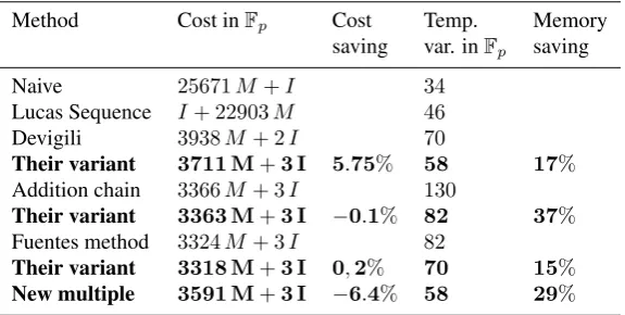
Table 1: Important result of computing the hard part of the final exponentiation.
Method Cost inFp Cost Temp. Memory
saving var. inFp saving
Naive 25671M +I 34
Lucas Sequence I+ 22903M 46
Devigili 3938M+ 2I 70
Their variant 3711 M+3 I 5.75% 58 17%
Addition chain 3366M+ 3I 130
Their variant 3363 M+3 I −0.1% 82 37%
Fuentes method 3324M+ 3I 82
Their variant 3318 M+3 I 0,2% 70 15%
New multiple 3591 M+3 I −6.4% 58 29%
of the pairing, but in our implementation we are interested by reducing memory usage. For this reason, we will present our implementation results of new variants presented by Duquesne et al in [2]. We will not present their studied methods, but we will just present its final results in the table 1; which give a comparison between Duquesne et al. [2] results and results given in the literature.
After studying mathematical aspect and finding the appropriate arithmetic opti-mization, we will apply the resulting algorithm and the hardware techniques to present an efficient hardware design, in the following section where we will detail all compo-nents used to compute Optimal Ate Pairing.
3
Pairing Processor Design
In this section, we will present our proposal optimal ate pairing hardware design. It is based on two steps: Miller Loop and Final Exponentiation. Based on Algorithm 1, the major operations to compute optimal ate pairing are divided into two categories:
1. Dependent operations which are:
• The point addition, point doubling, line computationl(Q)(in step 1, 2, and 10), andφ(Q)(in step 9): are performed inFp2,
• f2×l(Q),f×l(Q)(in step 5 and 6 respectively) are performed inFp12.
2. Independent operations which areFpoperations (multiplication, inversion, and
square).
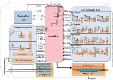
The data-path shown in Figure 1 uses serial/parallel approaches. According toFpk
sub-algorithm, it executes some of the independent operations in parallel, and disabled the others in order to save resources in pairing computations. For this reason, only one
Fpk arithmetic unit (Fpk AU) is used. It included independent operations to perform
Fpk sub-algorithms. The inputs data to theFpkAU come firstly from RDU, then from
multiplex every block in order to be used or disabled. In addition, it treat their requests and manipulate register access.
Figure 1: Pairing Computation Processor Design
Reducing the overall hardware costs of pairing computation is our first objective for designing the proposal architecture. It consists of several independent and dependent blocks which operate in serial or parallel according to the algorithm steps dependency. The whole architecture is based on five principal blocks which are:
1. The Random Data Unit (RDU): generated random values are need in the pair-ing first step, Random Number Generator (RNG), in other high level languages, is a function of a special library. But in VHDL, RNG is achieved by designing a pseudo-random sequence generator (PRSG) of suitable length. The RDU values will be the inputs of allFpkArithmetic Unit(FpkAU) and Pairing Functions Unit
(PFU).
2. The Storage Unit (SU): to calculate Frobenius, we have some precalculations to do, this values will be calculated once time and they will be constants during optimal ate computation. Precalculations stored in RAMs, will increase the area occupation and decrease execution time. In our design we need three different precalculations, so we will use three 256-bits-RAM. In every one we will store ten 256-bits-values.
3. The Control Unit (CU): is designed to control the flow of data in the design, as well as the movement of data between registers and the execution units (FpkAU
all the system blocks by sending control lines. After everyFpk operations, it
stores results in different registers to be used in the next step.
4. TheFpkArithmetic Unit (FpkAU): is the first block of the execution unit. It is
responsible for computing all arithmetic operations inFp,Fp2,Fp6andFp12. All
sub-algorithms are performed byFpkAU. Firstly, it uses random values to
exe-cute first arithmetic operations, and then stores results in the different registers as it is shown in Figure 1. Stored values will be the inputs of differentFpkAU
models.
5. The Pairing Function Unit (PFU): it’s the second block of the execution unit. It executes firstly the Miller Loop (Point Addition Step (PAS), Point Doubling Step (PDS) andφcalculus), then the Final Exponentiation . It uses results generated byFpkAU models to compute base algorithms.
In the next section, we will present the hardware optimizations used in our design to find the efficient way to compute optimal ate pairing.
4
Hardware Optimization
After algorithmic optimization presented in [2], we concentrated our optimization ef-forts on hardware design. The problem of hardware implementation is a function of two different factors: cryptographic algorithms architectures and the efficient integra-tion of them. The algorithms used to compute our optimal ate processor are partiintegra-tioned into a sequence of hardware implementable models. Every model represents the serial behavior of the algorithm and can be executed sequentially. In this section, we will present different optimizations done to perform our architecture.
4.1
Precalculation and RAM use
Precalculation is needed to compute Frobenius calculus. Its hardware implementation occupies an important memory and increases execution time. In order to face this problem, time and memory usage can be reduced by using a storage unit capable of storing all precalculation values and constants needed in our implementation using FPGA Block RAM features. In Xilinx FPGA, we find a distributed RAM’s used for implementing large and wide memory functions and it’s ideal for small sized memories. Xilinx can automatically connect several distributed RAM’s in parallel done by its synthesizer.
4.2
Arithmetic operation optimization
In most of the cryptosystems, there is a need of big number calculation. Operations complexities inFp6 andFp12 can be expressed in term ofFp arithmetic. So, it
the Karatsuba-Ofman, Toom-Cook, and FFT. Every algorithm has a certain complex-ity, which is essentially a measure for how long it takes to run the algorithm and the difficulty of computational problems against many different computational resources such as time, area etc. Thus, to design an efficient cryptosystem, computational com-plexity is a primordial step to choose algorithms that are easy to implement but hard to break. Karatsuba [30], Toom [33] and Cook [34] found polynomial multiplica-tion methods which have lower asymptotic complexity, fromO(n2)toO(ne), where
1< e≤log23. Many efforts have been done to find optimized implementations.
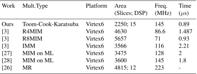
Table 2: Performance Comparison of different 256-bits Multiplier
Work Mult.Type Platform Area Freq. Time (Slices; DSP) (MHz) (µs)
Ours Toom-Cook-Karatsuba Virtex6 2250; 15 145 0.89
[3] R4MIM Virtex6 4630 86.6 1.487
[3] R8MIM Virtex6 5657 71 0.93
[3] IMM Virtex6 3566 116 2.21
[27] MIM on ML Virtex6 3475 128 2
[28] MIM on ML Virtex6 3600 145 1.8
[26] MR Virtex6 4815; 12 223
-Area occupation and running time are the most important constraints in hardware implementation. They depend on the algorithm steps. To find an efficient way to mul-tiply two number we can apply ”Divide and conquer algorithm” which is a method for solving a problem by dividing it into different sub-problems, each one is recur-sively solved, and the sub-problems solutions are then combined to find the solution to the main problem. One of the good approaches is to use Toom-Cook and Karatsuba methods. Karatsuba method was used to split the input numbers into limbs of smaller size and equal width, and then expresses the larger input product in terms of calcula-tions made on the smaller parts. Then, for the Toom-Cook multiplier, we could choose
B = 231 orB = 1090, and stored each digit as a separate 32-bit binary word. So,
to maximize FPGA’s resources exploitation, we used DSP features devices comput-ing 32-bits multiplication. After performcomput-ing multiplication, result should be reduced. The most used method is Montgomery reduction, specially by cryptosystems which are based on arithmetic operations modulo a large number. It is easier to be implemented in hardware, because the modulus reduction is done by shift operations avoiding the division operations (which are costly in execution time).
Table 2 compares the performance of our proposed 256-bits multiplier with different bits modular multiplication implementations in the literature. Our proposed 256-bits multiplier computes one multiplication using 2250 Slices and 15 DSP in only 0.89
µs achieving a maximum frequency of 145 MHz which is less area occupation com-paring to the others, and it presents the best compromise between area, frequency and execution time.
4.3
Miller Loop and Final Exponentiation optimization
Optimal ate pairing is based on Miller Loop and Final Exponentiation which needFpk
First, it can be implemented using one processor performing Miller Loop then final ex-ponentiation. Second, two separate processors can be implemented on which these two operations are pipe-lined. We should remark that two separate processors in pipeline help to reduce the computation time, but at the same time they need larger area.This paper attempts to optimize the area of the optimal ate pairing cryptoprocessor respect-ing a reasonable computation time. Our architecture is based on a common data-path for computing both the Miller algorithm and the Final Exponentiation one. The most famous methods to compute the hard part of the Final Exponentiation are listed and compared in Table 1. These new variant require less memory resources than the pre-vious ones, and offer a gain of complexity with a negligible losses in execution time which makes these method very interesting for hardware implementations.
Pairing
Miller Loop Final Exponentiation
φCalculus
Addition Step
Doubling Step
FpArithmetic
Fp2Arithmetic
Fp6Arithmetic
Fp12 Arithmetic
Multiplication
Square
Inversion
Figure 2: Pairing Computation Arithmetic
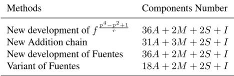
As it is mentioned in Table 3, the reuse ofFpkcomponents can limit the number of
components needed to compute every method of the hard part of the final exponentia-tion.
Table 3: Components Number Need for final exponentiation computation
Methods Components Number
New development offp 4−p2 +1
r 36A+ 2M + 2S+I
New Addition chain 31A+ 3M + 2S+I
New development of Fuentes 36A+ 2M + 2S+I
Variant of Fuentes 18A+ 2M + 2S+I
4.4
Component Use Optimization
Our approach, to implement our architecture, is based on reuse blocks as possible as we can, because every algorithm need a defined number of arithmetic operations which can be computed in parallel or serial. Let’s take the example ofFp6 multiplication in
Table 4: Clock distribution ofFp6Multiplication Module
Steps MFp2 Add1 Add2 Add3 Add4 Sub1 Sub2
1 X X X X X -
-2 X X X X X -
-3 X - - - - X X
4 - - - X X
5 X X - - - X
-6 X X X - - -
-7 - - - X X
8 - - - X X
9 - X X - - -
-10 - X X X - X
-11 - X X X X -
-12 X - - - - X X
13 - - - X X
Algorithm 4 (Appendix A). In every step, parallel operations can be executed in the same time, and in the next steps we can reuse the same components used before. So, here we apply the parallel approach first then the serial one and we dress Table 4. We can note that Fp6 multiplication algorithm need 6Fp2 multiplication blocks, 14
subtraction blocks (Subi) and 18 addition blocks (Addi). But, considering operation
independence, we will use only 2Fp2 multiplication blocks, 4 addition blocks and
2 subtraction blocks. The idea of activated and disabled components, can be more clear in Figure 3 (Appendix A). In every step, the component computing independent calculus was activated (with their special control lines: Go=1 and Reset=1) and the other components were disabled (Go=0 and Reset=0). We apply this approach toFp12
operations.
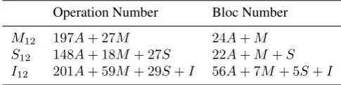
Table 5: Block Number Optimization for computing calculus inFp12
Operation Number Bloc Number
M12 197A+ 27M 24A+M
S12 148A+ 18M + 27S 22A+M +S
I12 201A+ 59M + 29S+I 56A+ 7M+ 5S+I
Our aim is to gain as much as possible on the number of used components, as it is mentioned in Table 5. We note that, concerningFp12 operations, arithmetic block
there was a 88%decrease in Addition blocks number , multiplication block’s number was 96%lower then before. In this way, the needs of the system resources are reduced and the system performance are increased . Another point is that our architecture design is composed of several independent synchronous components which operate with their own local synchronous clocks, we have a CLK Generator in the ACU, which generate a clock to every block in the entire architecture.
5
Implementation results
We have to highlight first, that every algorithm should be demonstrated in software, such as in our case, Optimal Ate Pairing Algorithms was verified using Sage Software in [35], then being implemented in hardware. The entire architecture of the optimal ate pairing processor is coded in VHDL language. Then, the code is simulated using the Modelsim 13.1 software, synthesized using Xilinx ISE 14.7 Design Suite, and im-plemented on a Virtex-6 FPGA(XC6VHX250T). Our hardware design compute, first the Miller Loop then the final exponentiation. Mathematical optimization of the hard part of the Final Exponentiation has a powerful effect on the performance of the en-tire architecture. So, by applying: mathematical optimizations cited in [2], hardware optimizations cited in section 4, then by the use of FPGA features (Block RAMs and DSP), the architecture cost, in terms of area and memory saving, was decreased.
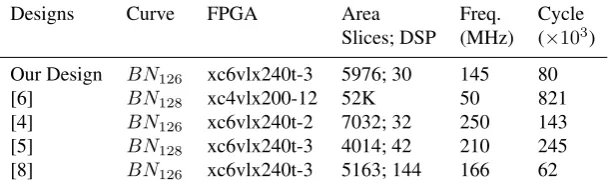
Table 6: Pairing Implementation results comparison
Designs Curve FPGA Area Freq. Cycle Slices; DSP (MHz) (×103) Our Design BN126 xc6vlx240t-3 5976; 30 145 80
[6] BN128 xc4vlx200-12 52K 50 821
[4] BN126 xc6vlx240t-2 7032; 32 250 143
[5] BN128 xc6vlx240t-3 4014; 42 210 245
[8] BN126 xc6vlx240t-3 5163; 144 166 62
Fp-Arithmetic operations, 74Kbit data memory and an instruction ROM implemented with FPGA Block RAMs, their design uses 4,014 Slices, 42 DSP48E1s and 5 Block RAMs (RAMB36E1s). In comparison with our results, we note that we use only 3 Block RAMs (RAMB36E1s) and 30 DSP48E1s, so our design is less costly, but de-sign in [5] presents a gain in frequency because it achieves a maximum frequency of 210 MHz. Analyzing a result given by S. Ghosh et all. [8], we note that they use in their design a higher number of DSP blocks comparing to other designs, due to the parallelism, we used 79% less DSP in our design, but the clock cycle count of [8] is slightly reduced comparing to our results.
As a conclusion, the results of the proposal design prove that it provides significant saving of area over the existing designs.
6
Conclusion and Future Work
Efficient hardware implementation is based on optimized and demonstrated algorithms. In this paper, we implemented optimal ate pairing algorithm exploring FPGA features devices. Our architecture is based on optimized algorithms which was demonstrated in software [35]. We evaluated our design performances, we found that our imple-mentation is less costly. These practical results prove that our optimized cryptographic architecture turned to consume as little system resources as possible, but it provided reasonable performance in the same time. For this reason, pairing implementations become more and more attractive for the hardware designers.
Nowadays a flexible encryption system, which would calculate arithmetic operations, can be implemented with hardware and software cooperation; hardware/software code-sign.
References
[1] Adjej.M, Boxall.j, Duquesne.S, Greuet.A, Haloui.S, Ionica.S ElMrabet.N, Rober.D, Rondepierre.F, Sanders.O “Examples of curves, pairings and algo-rithms for testing on SIM cards”; http : //simpatic.orange−labs.f r/wp−
content/uploads/2013/09/AN RIN S2012SIM P AT ICTask2D2−2.pdf.
[2] Duquesne, S., Ghammam, L.: “Memory-saving computation of the pairing final exponentiation on BN curves”; Groups Complexity Cryptology, to appear in 2016.
[3] Javeed, K., Wang, X.: “Radix-4 and Radix-8 Booth Encoded Interleaved Modular Multipliers over General Fp”; Field Programmable Logic and Applications (FPL), 24th International Conference on, 1-6 (Sep 2014).
[4] Cheung, R. C., Duquesne, S., Fan, J., Guillermin, N., Verbauwhede, I., Yao, G. X.: “FPGA implementation of pairings using residue number system and lazy re-duction”; pp. 421-441, in Proc. 13th Int. Workshop CHES, Springer, Heidelberg 2011.
[6] Ghosh, S., Mukhopadhyay, D., Chowdhury, D.R.: “High Speed Flexible Pairing Cryptoprocessor on FPGA Platform”; of Lecture Notes in Computer Science, pp. 450-466, 2010.
[7] Han, J., Li, Y., Yu, Z., Zeng, X.: “A 65 nm Cryptographic Processor for High Speed Pairing Computation”; IEEE Transactions on Very Large Scale Integration (VLSI) Sstems, Vol.23, NO.4, (Avril 2015).
[8] Ghosh, S., Verbauwhede, I., Roychowdhury, D.: “Core Based Architecture to Speed Up Optimal Ate Pairing on FPGA Platform”; Springer-Verlag Berlin Hei-delberg, 2013.
[9] Fan, J., Vercauteren, F., Verbauwhede, I.: “Faster Fp-arithmetic for cryptographic pairings on Barreto-Naehrig curves”; Int. Workshop CHES,in Proc. 11th , LNCS 5747, pp. 240-253. Lausanne, Switzerland 2009.
[10] Kammler, D.,Zhang, D., Schwabe, P., Scharwaechter, H., Langenberg M., Auras D., Ascheid G., Mathar, R.: “Designing an ASIP for Cryptographic Pairings over Barreto-Naehrig Curves”; Cryptographic Hardware and Embedded Systems-CHES 2009 (11th International Workshop Lausanne, Switzerland, September 6-9, 2009. Proceedings). Springer, 2009.(Lecture Notes in Computer Science; 5747).p. 254-271.
[11] Beuchat, J.L., Gonzalez-Diaz, J. E., Mitsunari, S., Okamoto, E., Rodriguez-Henriquez, F., Teruya, T.: “High-speed software implementation of the optimal ate pairing over Barreto-Naehrig curves”; Proc. 4th Int. Conf. Pairing-Based Cryp-tography 2010, LNCS 6487,pp. 21-39,Palo Alto, CA, USA.
[12] Vercauteren, F.: “Optimal pairings”; IEEE Trans. Inf. Theory, vol. 56, no. 1, pp. 455-461, (January 2010).
[13] Devegili, A. J., Scott, M., Dahab, R.:“Implementing cryptographic pairings over Barreto-Naehrig curves”; Pairing ’07, LNCS 4575, pp.197-207, 2007.
[14] Mitusunari, S.:“A Fast Implementation of the Optimal Ate Pairing over BN curve on Intel Haswell Processor”; Cryptology ePrint Archive, (June 2013).
[15] Ghosh, S., Mukhopadhyay, D., Roychowdhury, D.:“Secure Dual-Core Crypto-processor for Pairings Over Barreto-Naehrig Curves on FPGA Platform”; IEEE Transaction on Very Large Scale Integration Systems, vol.21, no.3, (March 2013).
[16] Shyam, V., Sujatha, D.:“FPGA Implementation of an Efficient and Highly Secure Cryptoprocessor over Barreto-Naehrig Curves”; Green Computing Communica-tion and Electrical Engineering (ICGCCEE), 2014 InternaCommunica-tional Conference on, pp.1-5, 2014.
[17] Sakiyama, K., Preneel, B., Verbauwhede, I.:“A fast dual-field modular arithmetic logic unit and its hardware implementation”; Circuits and Systems, 2006 IEEE International Symposium on. IEEE. pp. 4-pp, 2006.
[19] Al-Khaleel, O., Papachristou, C., Wolff, F., Pekmestzi K.:“Fpga based design of a large moduli multiplier for public-key cryptographic systems”; Computer Design ICCD . International Conference on. IEEE, pp. 314-319, 2006.
[20] Mondal, A., Ghosh, S., Das, A., Chowdhury D. R.:“Efficient fpga implementation of montgomery multiplier using dsp blocks”; Progress in VLSI Design and Test, pp. 370-372, Berlin, Heidelberg, Springer-Verlag, 2012.
[21] Huang, M., Gaj, K., El-Ghazawi, T.:“New hardware architectures for mont-gomery modular multiplication algorithm”; IEEE Transactions on computers, vol. 60, no. 7, pp. 923-936, 2011.
[22] Bunimov, V., Schimmler, M.:“Area and time efficient modular multiplication of large integers”; Application-Specific Systems, Architectures, and Processors, Pro-ceedings. IEEE International Conference on. IEEE, 2003.
[23] Unterluggauer, T., Wenger, E.:“Efficient Pairings and ECC for Embedded Sys-tems”; IACR and to Springer-Verlag, 2014.
[24] Xiaoxu Yao, G., Fan, J., Cheung, R. C. C., Verbauwhede, I.:“Faster Pairing Co-processor Architecture”; Pairing 2012, Springer-Verlag Berlin Heidelberg, LNCS 7708, pp. 160-176, 2013.
[25] Xilinx:“Logicore ip block gnenrator”; p. htt://www.xilinx.com., 2010.
[26] Aranha, D. F., Karabina, K., Longa, P., Gebotys, C. H., Lopez, J.:“Faster ex-plicit formulas for computing pairings over ordinary curves”; in Proc. 30th Annu. Int. Conf. Theory Appl. Cryptographic Eurocrypt, LNCS 6632, pp. 48-68, Tallinn, Estonia 2011.
[27] Chavez Corona, C., Moreno, E. F., Henriquez, F. R.:“Hardware design of a 256-bit prime field multiplier suitable for computing bilinear pairings”; in Reconfig-urable Computing and FPGAs (ReConFig), 2011 International Conference on. IEEE, pp. 229-234, 2011.
[28] Ghosh, S., Mukhopadhyay, D., Roychowdhury, D.:“Petrel: Power and timing attack resistant elliptic curve scalar multiplier based on programmable gf(p) arith-metic unit”; Circuits and Systems I: Regular Papers, IEEE Transactions on, vol. 58, no. 8,pp. 1798-1812, (Aug 2011).
[29] Nogami, Y., Akane, M., Sakemi, Y., Katou, H., Morikawa, Y.:“Integer variable chi-based ate pairing”; In Pairing- Based Cryptography - Pairing 2008, Second International Conference, Egham, UK, September 1-3, 2008. Proceedings, pages 178-191, 2008.
[30] Cook, S. A.:“On the minimum computation time of functions”; PhD thesis, De-partment of Mathematics, Harvard University, 1966.
[32] Aranha, D. F., Barreto, P. S. L. M.,Longa, P., Ricardini, J. E.:“The realm of the pairings”; In Selected Areas in Cryptography - SAC 2013 - 20th International Conference, Burnaby, BC, Canada, August 14-16, 2013, Revised Selected Papers, pages 3-25, 2013.
[33] Aranha, D. F., Karabina, K., Longa, P., Gebotys, C. H., L`opez, J.:“Faster Ex-plicit Formulas for Computing Pairings over Ordinary Curves”; Cryptology ePrint Archive, Report 2010/526, 2010,http://eprint.iacr.org/.
[34] Toom, A. L.:“The complexity of a scheme of functional elements realizing the multiplication of integers”; Soviet Mathematics Doklady, 3:714-716, 1963.
[35] Duquesne, S., Ghammam, L. https://cloud.sagemath.com/projects/332de229-174f-4d90-ae79-ca9d3b0fc1f7/files/Algorithms.sagews.
Appendix A:
Algorithm 4:
Input:a00, a01, a10, a11, a20, a21, c00, c01, c10, c11, c20, c21,p
Output :t8,t9,t6,t7,t0,t1
Step1:
t2,t3=M2(a10,c10,a11,c11)
V1, V2, V3, V4= (a10+a20,c10+c20,a11+a21,c11+c21)
Step2:
t6,t7=M2(V1,V2,V3,V4)
V1, V2, V3, V4= (a00+a10,c00+c10,a01+a11,c01+c11)
Step3:
t4,t5=M2(a20,c20,a21,c21)
t6, t7= (t6-t2, t7-t3)
Step4:
t6, t7= (t6-t4, t7-t5)
Step5:
t8,t9=(t6-t7, t6+t7)
t0,t1=M2(a00,c00,a01,c01)
Step6:
t8,t9=(t8+t0, t9+t1)
t6,t7=M2(V1,V2,V3,V4)
Step7:
t6,t7=(t6-t0,t7-t1)
Step8:
t6,t7=(t6-t2,t7-t3)
Step9:
t6, t7= (t6+t4, t7+t5)
Step10:
t6, t7=(t6-t5, t7+t4)
V1, V2= (a00+a20,c00+c20)
Step11:
t0,t1=(t0+t4, t1+t5)
V3, V4= (a01+a21,c01+c21)
Step12:
t0,t1=(t0-t2, t1-t3)
t2,t3=M2(V1,V2,V3,V4)
Step13:
clock
Reset
Start
ResetM2 GoM2
DataM2 z 1 2 3 4 5 6 7 8
Reset A1
Go A1
Data A1 z 1 2 3 4 5 6 7 8 z
Reset A2
Go A2
Data A2 z 1 2 3 4 5 6 7 8 z
Reset A3
Go A3
Data A3 z 1 2 3 4 5 6 7 8 z
Reset A4
Go A4
Data A4 z 1 2 3 4 5 6 7 8 z
Reset S1
Go S1
Data S1 z z
Reset S2
Go S2
Data S2 z z