TECHNICAL UNIVERSITY OF CLUJ-NAPOCA
ACTA TECHNICA NAPOCENSIS
Series: Applied Mathematics, Mechanics, and Engineering Vol. 62, Issue I, March, 2019
EXPERIMENTAL AND NUMERICAL STUDY ON JET ABRASIVE
MACHINING OF ALUMINUM 2024 – T3
Abderraouf GHERISSI, Ibrahim ElNASRI
Abstract: Abrasive jet machining is not very effective on soft materials, therefore for a highly efficient process, it is necessary to optimize the process parameters to increase the material removal rate and obtain a good surface quality on soft material. In the present work a new experimental and numerical investigation was carried out to optimize the abrasive jet drilling operation on aluminum 2024-T3. A high-velocity jet of air carrying fine abrasive particles of silica sand SiO2 was used to perform the
experiments. The abrasive jet machine used in this work can perform CNC drilling. The abrasive jet of SiO2 is given by the x- and z -axes while the specimen is motorized by the y-axis. The impact angle was
chosen as 90°. Through this work an experimental study of the material’s removal rate (MRR) at two different mass flow rates of abrasive particles (MP) was carried out. The numerical study was approximated to the impact of a single particle at MP=1.2 g/s with a particle jet velocity of around 200 m/s and for MP=2.2 g/s with a particle jet velocity of around 300 m/s. The numerical results for the eroded mass compared with the experimental results are close. The high precision, rapidity and efficiency of the present optimized process make it an alternative to traditional drilling processes.
Key words: abrasive jet drilling; material removal rate (MRR); mass flow rate of abrasive particles (MP); Aluminum 2024-T3.
1. INTRODUCTION
Abrasive jet machining (AJM) is a metal removing process that involves the application of a jet of gas carrying very fine abrasive particles on the top surface of a work piece. At high gas pressure and with the nozzle at a small standoff distance, the particles strike the work piece at high velocity, resulting in material removal through erosive action.
This erosive action has been employed mostly for cutting and drilling [1-4]. These two processes are quite effective on hard and brittle materials (glass, silicon, tungsten, ceramics, etc.) but not so effective on soft materials like aluminum, rubber, etc. AJM can produce fine and complicated details on parts made of very brittle materials.
For a highly efficient AJM process, it is necessary to optimize the process parameters to increase the material removal rate (MRR) while
obtaining a generated surface of good quality [5]. Several parameters have been discussed by many authors [6-23], such as the carrier gas, the size of abrasive grain, the velocity of the abrasive jet, the type and thickness of work material, the shape of the cut and tolerance, the life of the nozzle and the abrasive’s grain size effects.
The ongoing experimental tests on AJM demonstrate that the material removal rate (MRR) changes according to the material hardness properties [17-19]. The surface roughness of the process of AJM increases when the angle of blast is adjusted [20]. Besides, the surface roughness first increases with the impact duration, then reduces with further extension of the impact duration [21,22].
size [6], the air type and velocity [7], the shanking amplitude and level [8]. The erosion behavior in abrasive jet machining has been investigated based on the explicit finite element analysis (FEA) model by several authors, such as S. Dhar et al. [8].
2. DESIGN OF THE AJM AND
EXPERIMENTAL STUDY
AJM was designed to ensure that a high air flow at high pressure from an air compressor passes through filters and control valves into a shaking mixing chamber in which abrasive particles and the carrier gas are thoroughly mixed. The abrasive mixed gas passes through a nozzle onto the work piece, causing indentation on the work piece.
The indentation ultimately results in the capture of particles from the work surface [6]. The operation part in AJM is the CNC table, which is assembled and protected by a safety guard to prevent contact of the operator with the machine during the manufacturing process (Fig. 1).
Fig. 1: The CNC x-y-z table with safety guard
All axes are equipped by stepper motors to ensure the precision of displacement (Fig. 2). The nozzle is fixed in the z-axis to permit the cutting, engraving, drilling and polishing of work pieces (Fig. 2).
(a) The nozzle (b) The stepper motor
Fig. 2: The nozzle and stepper motor of the CNC AJM
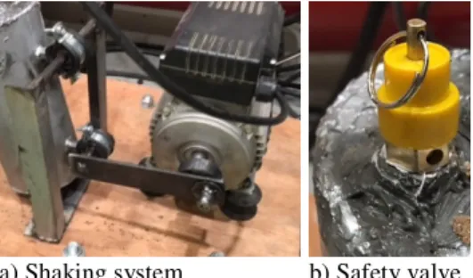
The shaking unit was manufactured and assembled as shown in Fig. 3. A safety valve is mounted in the abrasive container to prevent any air pressure risk. A concrete base was constructed to prevent any external movement of the shaking unit (Fig. 3).
The pressure relief valve (PRV) (Fig. 3) is a pressure safety valve (PSV) that meets the standards 1910 Occupational Safety and Health standards, and the ASTM E1575-12 Standard Practice for Pressure Water Cleaning and Cutting.
a) Shaking system b) Safety valve
Fig. 3: The shaking unit
To inspect and control the pressure and the flow rate, a control valve and pressure gauge are mounted just before the nozzle tip. In order to connect the CNC three-axis table with the software and the PC, it was necessary to provide a command unit (Fig. 4). The electronic assembly of the CNC controller and the electrical safety condition meet the standards ISO 10303-210 Application protocol: electronic assembly, interconnection, and packaging design.
The CNC system is composed of six major elements: input device, machine control unit, machine table, driving systems, feedback devices, and display unit. Fig. 4 shows a schematic diagram of the working principle of the NC axis of a CNC AJM and the interface with the CNC control.
material affect the efficiency of the AJM process.
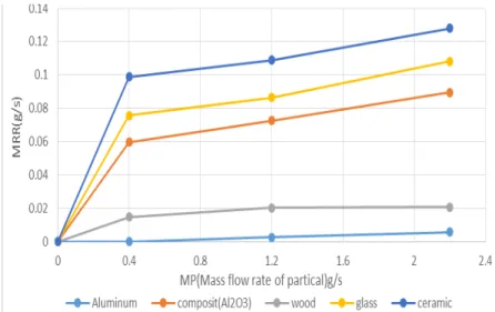
The abrasive flow rate and type of abrasive also affect the production and especially the MRR. The efficiency of the AJM process depends on nozzle wear, which in turn depends on many process parameters and geometrical parameters. In this study just, the effect of the mass flow rate (MP) of abrasive particles on the MRR is analyzed. The MP is switched from 0.4 to 2.2 g/s for a period of 30 s. The grain size is considered as constant during jet operation.
Figure 5 shows the experimental results of the impact of abrasive particles of SiO2 on different material specimens. The results show evidence that the best MRR will be for hard and brittle material and low MRR will be obtained for ductile material.
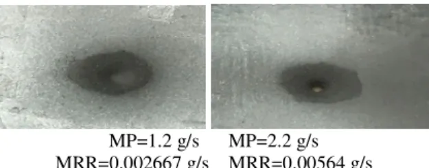
In the experimental study, the results from two different mass flow rates, MP=1.2 and MP=2.2 g/s, used to conduct the experiments were analyzed, calculating the MRR for aluminum 2024-T3 (Fig. 6).
Fig. 4: Diagram of the working principle of the NC axis of a CNC AJM
MP=1.2 g/s MP=2.2 g/s MRR=0.002667 g/s MRR=0.00564 g/s Fig. 6: Experimental results on abrasive machining of
aluminum 2024-T3 at MP=1.2 g/s and MP=2.2 g/s
A numerical study was performed to reproduce the experimental setup for the abrasive jet machine to give insight on the processes of material removal.
3. NUMERICAL STUDY
3.1 Finite element model
An explicit LS-DYNA code was used to reproduce the experimental setup for the abrasive jet machine [25]. Figure 7 shows the numerical model of the experimental setup, which is assumed as an impact ball on the aluminium sheet. The ball is modelled as a rigid body using the material type 20* (MATERIAL_RIGID, density = 2650 kg/m3, Young’s modulus = 75 GPa, Poisson’s ratio = 0.17). The aluminium is modelled as a brick element. The aluminium sheet used in the test has a square shape with a length of about 40 mm and thickness of 0.5 mm.
The impact ball is spherical with a 1.5 mm radius. The material of the ball is defined as
SiO2. The model consists of 44331 nodes, with 38673 3D elements (36000 for the aluminium sheet and 2673 for the rigid part). No refined meshing privilege zone is used in the computational model.
The element size of 0.66*0.66*0.05 mm3 in the central contact region was chosen based on a trade-off between the calculation cost and the accuracy, it was adjusted using several preliminary simulations with various mesh sizes (no significant mesh dependence was observed).
Eroding surface-to-surface contact was established between the ball and the aluminium sheet. All simulations assume that there is no friction contact.
Single integrated point meshes are used in the model, since the use of reduced integration
elements is robust in terms of overcoming negative volumes in nonlinear analysis, which are prone to occur in full integration elements. Despite these benefits, however, reduced integration elements suffer from nonphysical spurious/hourglass modes.
An hourglass control card based on Flanagan–Belytschko integration with a default hourglass coefficient is used to remove the hourglass modes. The aluminium sheet is clamped at the edge ends. The velocity of the ball is set as the initial velocity node.
Fig. 7 : Numerical model of the impact of jet abrasive machining of aluminum 2024-T3.
3.2 Constitutive model for the aluminum skin sheet
It has been reported by many authors that the aluminum 2024-T3 alloy is complex to analyze due to the care needed during the modelling of its anisotropic response and/or pressure and Lode angle parameter [26]. Meanwhile others [27-28] have claimed that the stress–strain behavior of aluminum 2024-T3 alloy is isotropic and insensitive to mean stress. It was thus decided to use the material model (MAT-DAMAGE_1) of LS-DYNA [25]. This choice was motivated by the relative simplicity of the model and the possibility of neglecting the material strain-rate effect. A model was chosen with the damageable isotropic hardening elastic-plastic constitutive law proposed by Lemaitre [29]. Such an isotropic damage model proposes a relationship between the effective stress and the damage accumulated plastic strain r, moderated by the isotropic damage variable D. The parameters used for aluminum 2024-T3 sheet as identified from normalized tension tests are given in Table 1.
Aluminu m sheet (40*40*0 .5 mm3)
Table 1: Parameters of isotropic damage model (MAT_DAMAGE_1) for aluminum 2024-T3
Parameters Value
ρ 2700 kg/m3
E 70 GPa
v 0.3
Q1 34.5 MPa
Q2 0 MPa
C1 47.32
C2 0
rD 0.18
S 0.5 MPa
Dc 0.1
4. RESULTS AND DISCUSSION
One of the important parts of successful utilization of the AJM process is the analysis of the different process criteria, especially the material removal rate. The abrasive particles are considered as spherical in shape and rigid. The complete kinetic energy of the particle is used to cut the material.
The material is considered to fail due to brittle fracture, and fracture of the volume is hemispherical with a diameter equal to the
chordal length of a particle of SiO2. For ductile material, the volume of material removal is assumed to be equal to the particle volume due to particulate impact [24].
The abrasive particles are directed at the work surface at high velocity through nozzles: 150, 200 and 300 m/s according to the position of the control valve.
The rate of material removal and the size of the machined area are influenced by the velocity because in this work the distance of the nozzle from the workpiece is considered as fixed.
The abrasive particles from the nozzle follow a parallel path. It is observed that the material removal rate initially increases with increase in the velocity of particles.
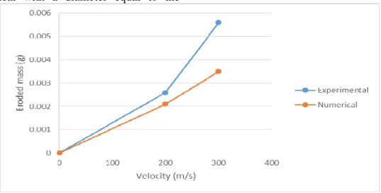
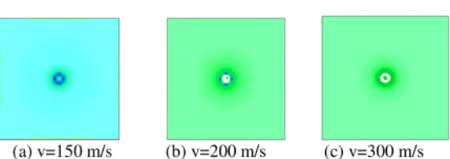
A comparison between the experimental material removal rate (MRR) and those from the simulation at 200 m/s and 300 m/s shows that the MRR for the simulation at 200 m/s is in relative agreement with the experimental value whereas there is a significant discrepancy at 300 m/s (Fig. 8). It can also be noted that there is no perforation of the aluminum sheet at the impact velocity of 150 m/s (Fig. 9a) but a full perforation of the plate at impact velocities of 200 m/s and 300 m/s (Fig. 9 b, c).
(a) v=150 m/s (b) v=200 m/s (c) v=300 m/s Fig. 9: Simulation results of impact of the abrasive particles on Al 2024-T3 at different impact velocities
(150 m/s, 200 m/s, 300 m/s).
Figure 10 shows the analysis of the aluminum sheet after impact erosion and illustrates a good agreement with the simulations results. As a result of the above numerical observation, the drilling of the aluminum 2024-T3 by abrasive SiO2 particles at the particle velocity of 200 m/s gives a result close to the experimental one, but the error in results becomes more remarkable at the velocity 300 m/s. Therefore, the model needs to be refined at the high velocity level to match the experimental results.
Fig. 10: Impact results on specimen of Al 2024-T3: experimental vs numerical at velocity v=200 m/s
5. CONCLUSION
The work shown in this paper was divided into experimental and numerical investigation of the drilling of aluminum 2024-T3. A high velocity jet of air carrying fine abrasive particles of silica sand SiO2 was used to perform the experiments.
An experimental study of the material removal rate (MRR) at different mass flow rates of abrasive particles (MP) was carried out. The numerical study was approximated to the impact of a single particle at MP=1.2 g/s relative to a particle velocity of around 200 m/s and for MP=2.2 g/s relative to a particle velocity of 300 m/s.
The eroded mass in both the experimental and numerical studies gives a contiguous result, where the maximum MRR for the drilling of the Al 2024-T3 was for the MP=2.2 g/s.
6. REFERENCES
[1] D. A. Axinte, D. S. Srinivasu, M. C. Kong, P. Butler-Smith, Abrasive waterjet cutting of polycrystalline diamond: A preliminary investigation, International Journal of Machine Tools and Manufacture, 2009,
49(10):797-803, DOI
10.1016/j.ijmachtools.2009.04.003
[2] H. Nakamura, M. Nakamura, N. Osuga, H. Miyazawa, Application of an air-abrasive cutting apparatus in the pediatric dental field: Cutting using chitin-chitosan grains, Pediatric Dental Journal , 2006, 16(1):57-66, DOI https://doi.org/10.11411/pdj.16.57 [3] K. Rajasekhara Reddy, D.V. Srikanth,
Investigation of drilling time vs depth of cut & kerf using abrasive jet machining, IOSR Journal of Mechanical and Civil Engineering (IOSR-JMCE), 2015, 12(6): 54-61.
[4] S. Manikyam Reddy, S. Hussain, D. V. Srikanth, M. Sreenivasa Rao, Experimental analysis and optimization of process parameters in machining of RCFRP by AJM, International Journal of Innovative Research in Science, Engineering and
Technology, 2015, 4(8),
DOI:10.15680/IJIRSET.2015.0408053 [5] F.-C. Tsai, B.-H. Yan, C.-Y. Kuan, R.-T. Hsu,
J.-C. Hung, An investigation into superficial embedment in mirror-like machining using abrasive jet polishing, Int. J. Adv. Manuf. Technol., 2009, 43:500–512, DOI 10.1007/s00170-008-1734-8
[6] B. Chandra, A study of effect of process parameters of abrasive jet machining,
International Journal of Engineering Science and Technology, 2011, 3(1):504– 513.
and analytical model, Wear, 2013, 303:138–145.
[8] F. Chen, X. Miao, Y. Tang, S. Yin, A review on recent advances in machining methods based on abrasive jet polishing (AJP), Int. J. Adv. Manuf. Technol., 2017, 90:785– 799.
[9] D. Venturini, M. S. Cenci, F. F. Demarco, G. B. Camacho, J. M. Powers, Effect of polishing techniques and time on surface roughness, hardness and microleakage of resin composite restorations, Operative Dentistry, 2006, 31(1):11-17.
[10] K. Guará Brusaca Almeida Scheibe, K. Guará Brusaca Almeida, I. Studart Medeiros, J. Ferreira Costa, C. Maria Coêlho Alves,
Effect of different polishing systems on the
surface roughness of microhybrid
composites, J. Appl. Oral Sci., 2009,17 (1). [11] M. A. Chinelatti, D. T. Chimello, R. P.
Ramos, R. G. Palma-Dibb, Evaluation of the surface hardness of composite resins before and after polishing at different times, J. Appl. Oral Sci., 2006, 14(3):188-192 . [12] G. S. Aswal, C. K. Nair, Effects of various
parameters of alumina air abrasion on the mechanical properties of low-fusing feldspathic porcelain laminate material, SADJ, 2015, 70(4):150-155.
[13] T. Kulunk, M. Kurt, Ç. Ural, Ş. Kulunk, S. Baba, Effect of different air-abrasion particles on metal-ceramic bond strength, Journal of Dental Sciences, 2011, 6:140-1460.
[14] D. Arola, A. E. Alade, W. Weber, Improving fatigue strength of metals using abrasive waterjet polishing, Machining Science and Technology, 2006, 10:197-218.
[15] A. Azhari, S. Sulaiman, A. K. Prasada Rao, A review on the application of polishing processes for surface treatment, IOP Conf. Series: Materials Science and Engineering, 2006, 114:012002.
[16] F. Boud, L. F. Loo, P. K. Kinnell, The impact of plain waterjet machining on the surface integrity of aluminium 7475, Procedia CIRP, 2014, 13:382- 386.
[17] K. T. Choa, K. Song, S. H. Oh, Y.-K. Lee, K. M. Lim and W. B. Lee, Surface hardening
of aluminum alloy by shot polishing treatment with Zn based ball, Materials Science and Engineering A, 2012, 543:44– 49.
[18] E. S. Abdel Nasser, A. Elkaseer, A. Nassef,
Abrasive jet machining of glass:
Experimental investigation with artificial neural network modelling and genetic
algorithm optimization, Cogent
Engineering, 2016, 3:1276513.
[19] D. Alman, J. Tylczak, J. Hawk, M. Hebsur,
Solid particle erosion behavior of a Si3N4– MoSi2, Mater. Sci. Eng. A, 1999, 261:245-251.
[20] M. W. Chastagner, A. J. Shih, Abrasive jet
machining for edge generation,
Transactions of NAMRI/SME, 2007, 3. [21] A. A. Khan, N. B. Munajat, H. B. Tajudin, A
study on abrasive water jet machining of aluminum with garnet abrasives, Journal of Applied Science, 2005, 5(9):1650‐1654. [22] S. Dhar, T. Krajac, D. Ciampini, M. Papini,
Erosion mechanisms due to impact of single angular particles, Wear, 2005, 258:567-579.
[23] V. C. Venkatesh, Parametric studies on abrasive jet machining, Annals of the CIRP, 1984, 33(1):109.
[24] R.B. Shukla, Abrasive jet machining, Proc. Abra. Eng. Soc. Conf., 1985, 23:91-100. [25] LS-DYNA, Keyword user’s manual,
Livermore Software Technology Corporation. Version 971, 2007.
[26] J. O. Hallquist, Theoretical manual. Livermore Software Technology Corporation, 1998.
[27] J. D. Seidt, A. Gilet, Plastic deformation of 2024-T351 aluminum under a wide range of loading conditions, Int. J. Solid Structs., 2013, 50(10):1781-1790.
[28] D. R. Lesuer, Experimental investigations of material model for Ti-6Al-4V titanium and 2024-T3 aluminum, Technical Report DOT/FAA/AR-00/25. Lawrence Livermore National Laboratory, Livermore, 2002. [29] J. Lemaitre, A course on damage mechanics.
STUDIU EXPERIMENTAL ȘI NUMERIC PE JET ABRAZIVE DE PRELUCRARE DIN ALUMINIU 2024-T3
Rezumat: Prelucrarea cu jet abraziv nu este foarte eficientă pe materiale moi, prin urmare, pentru un proces extrem de eficient, este necesar să se optimizeze parametrii procesului pentru a crește rata de îndepărtare a materialului și de a obține o calitate bună a suprafeței pe material moale. În lucrarea de față a fost efectuată o nouă investigație experimentală și numerică pentru optimizarea operațiunii de foraj cu jet abraziv pe aluminiu 2024-T3. Un jet de mare viteză de aer care transportă particule fine abrazive de nisip de siliciu SiO2 a fost folosit pentru a efectua experimente. Mașina cu jet abrazivă utilizată în această lucrare are capacitatea de a efectua forarea CNC. Jet abraziv de SiO2 este motorizat de x-și z-axe în timp ce specimenul este motorizat de axa y. Unghiul de impact a fost ales ca 90 °. Prin intermediul acestei lucrări a fost efectuat un studiu experimental al ratei de îndepărtare a materialului (MRR) la două rate diferite ale fluxului de masă ale particulelor abrazive (MP). Studiul numeric a fost aproximat la impactul unei singure particule la MP = 1.2 g/s cu o viteză cu jet de particule de aproximativ 200 m/s și pentru MP = 2.2 g/s cu o viteză cu jet de particule de aproximativ 300 m/s. Rezultatele numerice pentru masa erodate în comparație cu rezultatele experimentale sunt apropiate. Precizia ridicată, rapiditatea și eficiența procesului optimizat actual fac din aceasta o alternativă la procesele tradiționale de foraj.
Abderraouf GHERISSI, Assistant Professor, University of Tabuk, College of Engineering Mechanical Engineering Department. Email: [email protected], Address: Mechanical Engineering Department, College of Engineering, University of Tabuk, P.O. Box: 741, Tabuk 71491, Saudi Arabia. Tel: +966543440530