PERFORMANCE COMPARISON OF BOOST CONVERTER
BY USING FUZZY LOGIC CONTROLLER
Deepa.T
VIT University, Vandalur Kelambakkam Road,Chennai.
India.
ABSTRACT
This paper determines the performance of boost converter using PI controller and fuzzy controller. Normally, boost converter has non-linear properties, because of its properties, fuzzy controllers have been applied. When fuzzy controllers are applied practically in individual, it has so many disadvantages despite of its suitable characteristics. For controlling a boost converter, fuzzy controller was proposed. Although, it has disadvantages but it has also its own advantages that are suited for the control design. For designing and verifying the results of a fuzzy controller, PI controller should also use. The experimental results of the proposed boost converter using fuzzy control are evaluated in comparison with results using PI controller. The comparison of both the results indicates that the fuzzy controller is able to obtain better settling response than PI controller.
Keywords
Fuzzy Controller; PI Controller; Boost Converter; Control design.
1.
INTRODUCTION
Basically two different control techniques are applied to dc-dc converters, they are PI-controller and fuzzy controller. Fuzzy control technique is a non-linear control technique, while PI- control technique is a linear technique used for various industrial applications.
Frequency response techniques are used to design the PI controller for dc-dc converters [1]. Generally, to determine the loop gain, cross-over frequency, gain margin and the phase margin, bode plot is used. Phase margin is used to determine the stability of the proposed system. But PI controllers can only designed for one nominal operating point of the system. As the small signal model of the boost converter varies, the operating point varies. Both the poles and a right-half plane are zero and also the magnitude of the frequency response, are all dependent on the duty cycle. Therefore, for PI controller it is very difficult to respond the changes in operating point.
radiations and temperature. In this paper we analyze the equations of a boost converter and propose a design components and simulation of DC/DC boost converter. This work is applied to photovoltaic system for tracking the point of maximum power.
Mattavelli et al, discussed based on a qualitative description of the system to be controlled, fuzzy controllers are capable of good performances, even for those systems where linear control techniques fail, e.g., when a mathematical description is not available or is in the presence of wide parameter variations. The presented approach is general and can be applied to any DC-DC converter topologies. Controller implementation is relatively simple and can guarantee a small-signal response as fast and stable as other standard regulators and an improved large-signal response. Simulation results of buck-boost and Sepic converters show control potentialities.
The PID compensator generates the corresponding duty cycle based on the error signal [5]. Luo et al, presented the control strategy for the static synchronous compensator (STATCOM) used in utility distribution systems is investigated, and a novel fuzzy-PI-based direct-output-voltage (DOV) control strategy is presented. Based on power balancing principle and feed forward decoupling control, this novel DOV control strategy cannot only reduce the active and reactive current control loops of a conventional double-loop control strategy but also achieve the decoupling control to regulate dc-link voltage and maintain the voltages at the point of common coupling (PCC). In order to effectively improve the immunity capability of this novel DOV control strategy to the uncertainties in system parameters, two fuzzy PI controllers are separately employed to maintain the voltages at the PCC and to simultaneously regulate dc-link voltage.
So et al designed a fuzzy logic controller for dc/dc converters is described in this paper. A brief review of fuzzy logic and its application to control is first given. Then, the derivation of a fuzzy control algorithm for regulating dc/dc converters is described in detail. The propo11pe101-sosed fuzzy control is evaluated by computer simulations as well as experimental measurements of the closed-loop performance of simple dc/dc converters in respect of load regulation and line regulation.
Kamyar Mehran et al. applied a novel Takagi-Sugeno (TS) fuzzy-model-based approach to prohibit the onset of subharmonic instabilities in dc-dc power electronic converters. The use of a model-based fuzzy approach derived from an average mathematical model to control the nonlinearities in power electronic converters has been reported in the literature, but this is known to act as a low-pass filter, thus ignoring all nonlinear phenomena occurring at converter clock frequency.
A fuzzy bilinear state feedback controller based on Tagaki–Sugeno (TS) fuzzy bilinear model for DC–DC converters is presented [9] . The DC–DC converters can be approximated to bilinear model via Taylor series expansion. For achieving the output voltage regulation, to formulate the extended system of bilinear DC–DC converter model, one of whose state variables is the error between the output voltage and the reference output voltage. The extended system can be described to TS fuzzy bilinear model. We design a fuzzy bilinear state feedback controller to track the reference output voltage. The closed loop system is globally asymptotically stable via the proposed controller. Lyapunov theory is employed to guarantee the stability of the closed loop system. Numerical examples are given to demonstrate the validity of our proposed control approach with comparative results.
The design of fuzzy controllers is mainly based on the knowledge of system instead of a particular mathematical model. The Fuzzy controllers are designed to adapt to the non-linear properties of boost converters under varying operating points. Based on the issues of design and implementation, PI controller and fuzzy controller are compared. Finally, the experimental results of the boost converter using PI-controller and fuzzy controller methods are evaluated and compared.
2.
DESIGN OF BOOST CONVERTER
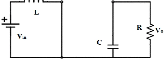
Four components are needed to design a boost converter. They are: Inductor (L), capacitor (C), switch (S) and Diode (D). The boost converter operates in two different modes depending on its switching period storage capacity and its relative length.
Fig. 1. Step-up dc-dc converter
1.1
Mode-1:
When MOSFET switch (S) is switched ON at the interval t=0 and terminates at the interval t=𝐭𝐨𝐧, then the mode-1
operation begins. The equivalent circuit for the mode-1 operation model is shown in the fig.1. The inductor current 𝐢𝐋(t)
is greater than zero and it ramps up linearly. The inductor voltage is 𝐕𝐢𝐧.
Fig.2. Mode-1 operation of Boost converter
1.2
Mode-2
When MOSFET switch (S) is switched off at the interval t=𝑡𝑜𝑛 and terminates at the interval t=𝑡𝑠, then the mode-2
Fig.3. Mode-2 operation of Boost Converter
𝑉𝑖𝑛 ∗ 𝑡𝑜𝑛+ 𝑉𝑖𝑛 − 𝑉𝑜𝑢𝑡 ∗ 𝑡𝑜𝑓𝑓 = 0 (1)
Where,
𝑉𝑖𝑛 = The input voltage, Volts.
𝑉𝑜𝑢𝑡 = The average output voltage, Volts.
𝑡𝑜𝑛 = The turn- ON time of MOSFET switch, sec. 𝑡𝑜𝑓𝑓 = The turn- OFF time of MOSFET switch, sec.
Dividing equation-1 with 𝑇𝑠 on both the sides and by rearranging [2], we get
𝑉𝑜𝑢𝑡
𝑉𝑖𝑛 = 𝑇𝑠 𝑡𝑜𝑓𝑓 =
1
1−𝐷 (2)
Where,
𝑇𝑠= The total switching period, sec.
D= Duty Cycle.
Fig.4. Simulink model of Boost Converter.
For finding the inductor and capacitor‟s critical values,
Capacitance C = (
Io fs*
D
∆Vo
)
(3)
Inductance L = (
Vin fs*
D
∆Iin
)
(4)
3.
BOOST CONVERTER WITH PI CONTROLLER
For boost converter operation, a PI controller is designed during steady state and it can reduce the oscillations in the duty cycle.
1.3
Closed loop of Boost Converter
The following four parameters are required to do the closed loop of boost converter.
Input voltage=18-30v Output voltage=210v
Maximum output current=1.2A
Integrated circuit to build up the converter
1.4
Transfer function of Boost Converter
For any system to control the control parameters are very essential, as we all know that the PI controller parameters can be obtained from the closed loop transfer function of the boost converter.
Vout
Vin
=
R L ∗s
[1+ L ∗sR ∗ Kp+K is ∗ 1−D1 ]
(5)
In closed loop, PI control is a program to control the pulse width modulator like the function generator and added by the feedback control. This will helps in getting the constant output from the boost converter.
PI controller controls the input to give the constant output.
Table- I. Design Specifications of Proposed Boost Converter
PARAMETER RATING
Input voltage range 18-30 V
Output voltage 210V
Power 240W
Duty cycle 85.7%
Inductance, capacitance 643µH, 1µF.
Switching frequency 50kHz
Load resistance 200Ω
KP, Ki 2.85*10^-4 , 0.1
Fig.6. Input Current and Voltage Waveforms of Boost Converter
Fig.7. Output Voltage and Output Current responses of open loop converter
4.
FUZZY CONTROLLER FOR A BOOST CONVERTER
Boost converter‟s small signal model is having a non-linear function across the duty cycle, a non-linear control method i.e. fuzzy control technique is applied to control the boost converters. For fuzzy controllers, there is no need of a particular mathematical model. Instead of using exact mathematical model, they are designed totally on the basis of general knowledge of the plant. Fuzzy controllers has been designed to adapt the operating points from where it is varying.
Fig.9. Boost Converter with Fuzzy Control
For building a fuzzy block, four main components are needed:
1. Fuzzification: It can convert the input into information that which the inference mechanism use to activate and apply the rules.
2. Rule Base: It contains the description that how to get the good control.
3. Inference Mechanism: It evaluates that which rules of control are relevant to use in this scenario, and
4. De-Fuzzification: It can interface that converts the inference mechanism‟s conclusion into the control input to the system [3].
Two inputs should be given to the fuzzy controller of the boost converter. First input is the error in output voltage e[i]=Ref-ADC[i], where ADC[i] is the converted digital value of the 𝑖𝑡ℎ sample of output voltage and „Ref‟ is the digital
Table-II. Fuzzy Controller Rules
MN NB N Z P PB MP
MN MN MN MN MN NB N Z
NB MN NB NB NB N Z P
N MN NB N N Z P PB
Z MN NB N Z P PB MP
P NB N Z P P PB MP
PB N Z P PB PB PB MP
MP Z P PB MP MP MP MP
4.1
Comparison of the design of PI controller with the design of the Fuzzy controller
PI controller design procedure is different from the fuzzy controller procedure. Frequency response is considered for the PI controller based boost converter and the required frequency will get at one particular operating point of the output response. As the duty cycle varies, the magnitude response and the response of the obtained frequency varies.
When considering the fuzzy controller, a particular mathematical model analysis is not needed. Mainly, it depends on the general knowledge.
Response obtained in the PI controller is linear and it mainly depends on the particular factors like bandwidth, gain margin, phase margin….etc. For knowing these factors, there are more tools available in PI controller. For Fuzzy controllers, there are few tools available because it is based on the human‟s knowledge and analysis is also difficult. It also need extensive tuning to get the required response.
5.
SIMULATION RESULTS
In this section, experimental results of both the controllers are discussed.
Fig.10. Output Response of the PI Controller based
Boost Converter Fig.11. Output Response of the Fuzzy Controller based
6.
CONCLUSION
For better performance of the boost converter, several controlling techniques are used. In this paper, PI controller and fuzzy controller are used. For obtaining the steady response of the converter, PI controller is used and this response is mainly depends on the frequency response of the boost converter. The design of fuzzy controller depends on the expert knowledge of the boost converter and it is tuned using trial and error method. We apply two different models of the fuzzy controller i.e. one is to get faster response and the other is to reduce the steady state error.
After implementing the design and parameters in the boost converter, the results of the both PI controller and fuzzy controller are compared. For designing the PI controller, it has different procedures but it doesn‟t require particular mathematical model. Fuzzy controllers requires more tuning than PI controller because for designing, it demands more computation power. Despite of the issues mentioned above, it has its own advantages over the linear controllers. After comparison, the settling response of the fuzzy controller is faster than the PI controller with lesser disturbances The heading of a section should be in Times New Roman 12-point bold in all-capitals flush left with an additional 6-points of white space above the section head. Sections and subsequent sub- sections should be numbered and flush left. For a section head and a subsection head together (such as Section 3 and subsection 3.1), use no additional space above the subsection head.
7.
REFERENCES
[1] R. P. Severns, G. Bloom. 1985, Modern DC-To-DC Switchmode Power Converter Circuits. Van Nostrand Reinhold.
[2] Mohammed, B. M Hasaneen, and Adel A. Elbaset. "Design and Simulation of DC-DC Boost Converter," 2008.
[3] K. M. Passino, S. Yurkovich, Fuzzy Control. Addison-Wesley 1997.
[4] P. Mattavelli, L. Rossetto, G. Spiazzi, P. Tenti, General-purpose fuzzy controller for dc–dc converters, IEEE Transactions on Power Electronics 12 (1997) 79–86..
[5] A. Prodic, D. Maksimovic, Design of a digital PID regulator based on look-up tables for control of high-frequency dc–dc converters, in: Proceedings of IEEE Workshop on Computers in Power Electronics, 2002, pp. 18–22.
[6] A. Luo, C. Tang, Z. Shuai, J. Tang, X.Y. Xu, D. Chen, Fuzzy-PI-based direct-output voltage control strategy for the STATCOM used in utility distribution systems, IEEE Transactions on Industrial Electronics 56 (2009) 2401–2411M.
[7] W.-C. So, C.K. Tse, Y.-S. Lee, Development of a fuzzy logic controller for dc–dc converters: design, computer simulation, and experimental evaluation, IEEE Transactions on Power Electronics 11 (1) (1996) 24–32.
[8] Kamyar Mehran, Damian Giaouris, and Bashar Zahawi, “Stability Analysis and Control of Nonlinear Phenomena in Boost Converters Using Model-Based Takagi–Sugeno Fuzzy Approach”, IEEE Trans. Circuits Syst. I, Reg. Papers, vol. 57, no. 1, pp. 200–212, Jan. 2010.
[9] Jaeho Baek, Mignon Park, “Fuzzy bilinear state feedback control design based on TS fuzzy bilinear model for DC–DC converters”, International Journal of Electric Power and Energy Systems 42 (2012) 710–720.