Enhancement of Micro Grid Power Quality with cascaded
Voltage-Current control
1
Ms. B.Gayathri,
2Mr.M.Nagaraju
Dept of EEE Audisankara Institute of Technolog Gudur, Nellore (DT)
Abstract:
Microgrid (MG) is the indispensable infrastructure of now smart grid, however, variation and intermittence caused from unstable sources and nonlinear loads will execute considerable impacts on normal operation of the MG. The micro-grid is paradigm of the first-time, examination in this area is rising incessantly. The wind energy generation, utilization and its grid penetration in electrical grid are growing world-wide. The wind produced power is continuously changing due to its time varying nature and causing stability problem. Unified Power Flow Control (UPFC) is used to control the power flow in the transmission system by controlling the impedance, voltage magnitude and point approach. Injection of wind power into an electric grid affects the power quality. The performance of the wind turbine and thereby power quality are determined on the basis of measurements and the norms followed according to the guideline specified in International Electro technical Commission standard, IEC-61400-21. The influence of the wind turbine in the grid system concerning the power quality measurements are the active power, reactive power, variation of voltage, flicker, harmonics, and electrical behavior of switching operation. The paper study demonstrates the power quality problem due to installation of wind turbine with the grid. In this proposed scheme STATIC COMPENSATOR (STATCOM) is connected at a point of common coupling to mitigate the power quality issues. The STATCOM control scheme for the grid connected wind energy generation system is simulated using MATLAB/SIMULINK in power system block set.
I. Introduction
To have sustainable growth and social progress, it is necessary to meet the energy need by utilizing the renewable energy resources like wind, biomass,hydro,cogeneration,etc.Theneedtointegrate Renewable energy like wind energy into power system is to make it possible to minimize the environmental impact on conventional plant [1]. The issue of power quality is of great importance to the wind turbine [2]. In the fixed speed wind turbine operation, all the fluctuation in the wind speed are transmitted as fluctuations in the mechanical torque, electrical power on the grid and leads to large voltage fluctuations. A STATCOM based control technology has been proposed for improving the power quality which can technically manages the power level associates with the commercial wind turbines. The paper is organized as follows. The Section II introduces the power quality standards, issues and its consequences of wind turbine [3]. The Section III describes the topology for power quality improvement. The Section IV, V, VI, VII, VIII, IXandX, discusses on the control design as well as the test system waveforms/results and conclusion respectively. II. Micro Grid
Micro grid [4] may be defined as an agglomeration of Distributed generation (DG) units
III. UNIFIEDPOWERFLOWCONTROLLER(UPFC)
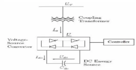
Figure 1: Basic Structure of an UPFC.
The UPFC consists of a series and a shunt converter is connected back-to-back through a common dc link. The shunt converter is connected also in parallel with the line transmission by transformer, allows controls the UPFC bus Voltage/shunt reactive power and the dc capacitor voltage.
Vs = AVr + BIr (1)
Is = CVr + BIr (2)
The ABCD Constants of a line of length 1, having a series impedance of Z ohm/km and shunt admittance of y S/km, are given by
A=D=cosh (λl) B = Zcsins (λl) C = sinh (λl)/Zc (3) Where
λ=√
ZY and
√Z/YThe active and reactive power flows at the SE and RE of the line can be written as
Ps = C1 cos (β-α) –C2cos (β-δ) (4) Qs =C1 sin(β-α) –C2 sin (β-δ) (5)
Pr = C2 cos(β-δ) –C3cos (β-α) (6) Qr = C2 cos (β-δ) –C2cos (β-α) (7)
Where
C1 = AVs²/B C2 = VsVr/B C2 = AVr²/B
IV. Static Synchronous Compensator (Statcom) Basically, STATCOM is comprised of three main parts (as seen from Figure below): a voltage source converter (VSC), a step-up coupling transformer, and a controller. In a very-high-voltage system, the leakage inductances of the step-up power transformers can function as coupling reactors [7].The main purpose of the coupling inductors is to filter out the current harmonic components that are generated mainly by the pulsating output voltage of the power converters [8].
Figure 2: Basic Struture of STATCOM.
V. POWER QUALITY IMPROVEMENT WITH
CONTROLLERS
The primary level with local controllers of DG employs a PI controller to generate the unbalance compensation reference for the
microgrid DGs.The low bandwidth
communication links are used to transmit the reference generated by the PI controller to the primary level local controllers of DG [9]. Identical power rating Distributed Generator units are used used in this work, which take care of compensation due to unbalance.
In the scheme of [10] the following drawbacks are identified:
1. The author analyzed the voltage unbalance compensation for an autonomous mode micro grid at Point of common coupling.
2. The author originated the unbalance by using linear unbalanced load.
3. The author tackled the problem using droop controllers for the load current compensation in the positive sequence component.
SLB is compensated. As listed in the shortcomings of [13], the author evaluated the micro grid analysis for both grid connected and islanded modes. A different problem interpretation was projected in reference [14], where they regarded improvement of voltage and power sharing. A control method was proposed, in that the control tasks were separated in the frequency domain. In order to allocate the control among a central controller and local controllers for every inverter, the principle is adopted .Voltage and Power sharing are regulated centrally and a low-bandwidth communication link was used to distribute the orders. Functions of Waveform quality are regulated in high bandwidth regulators distributed to every local inverter. During transients and steady state, the circulating currents are evaded.
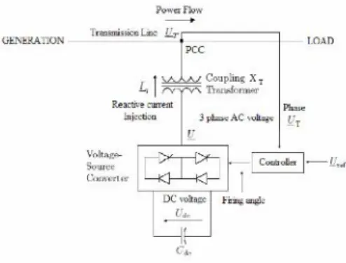
I. Basic Operating Principles Of Statcom The STATCOM is connected to the power system at a PCC (point of common coupling), through a step-up coupling transformer, where the voltage-quality problem is a concern. The PCC is also known as the terminal for which the terminal voltage is UT. All required voltages and currents are measured and are fed into the controller to be compared with the commands. The controller then performs feedback control and outputs a set of switching signals (firing angle) to drive the main semiconductor switches of the power converter accordingly to either increase the voltage or to decrease it accordingly. A STATCOM is a controlled reactive-power source. It provides voltage support by generating or absorbing reactive power at the point of common coupling without the need of large external reactors or capacitor banks. Using the controller, the VSC and the coupling transformer, the STATCOM operation is illustrated in Figure below.
Fig 3: STATCOM operation in a power system.
The charged capacitor Cdcprovides a DC voltage, Udc to the converter, which produces a set of controllable three-phase output voltages, U in synchronism with the AC system. The synchronism of the three-phase output voltage with the transmission line voltage has to be performed by an external controller. The amount of desired voltage across STATCOM, which is the voltage reference, Uref, is set manually to the controller. The voltage control is thereby to match UTwith Uref which has been elaborated. This matching of voltages is done by varying the amplitude of the output voltage U, which is done by the firing angle set by the controller. The controller thus sets UTequivalent to the Uref. The reactive power exchange between the converter and the AC system can also be controlled. This reactive power exchange is the reactive current injected by the STATCOM, which is the current from the capacitor produced by absorbing real power from the AC system.
VII.Powerquality Standards, Issues And Its Consequences
A. International Electro Technical Commission Guidelines:
The guidelines are provided for measurement of power quality of wind turbine. The International standards are developed by the working group of Technical Committee-88 of the International Electro-technical Commission (IEC), IEC standard 61400-21, describes the procedure for determining the power quality characteristics of the wind turbine [15]. The standard norms are specified. 1) IEC 61400-21: Wind turbine generating system, part-21.
Measurement and Assessment of power quality characteristic
Of grid connected wind turbine
2) IEC 61400-13: Wind Turbine—measuring procedure in
Determining the power behavior.
3) IEC 61400-3-7: Assessment of emission limit for fluctuating
Load IEC 61400-12: Wind Turbine performance. The data sheet with electrical characteristic of wind turbine provides the base for the utility assessment regarding a grid connection.
B. Voltage Variation:
power variations. The voltage variation is commonly classified as under:
• Voltage Sag/Voltage Dips. • Voltage Swells.
• Short Interruptions.
• Long duration voltage variation.
The voltage flicker issue describes dynamic variations in the network caused by wind turbine or by varying loads. Thus the power fluctuation from wind turbine occurs during continuous operation. The amplitude of voltage fluctuation depends on grid strength, network impedance, and phase-angle and power factor of the wind turbines. It is defined as a fluctuation of voltage in a frequency 10–35 Hz. The IEC 61400-4-15 specifies a flicker meter that can be used to measure flicker directly.
C. Harmonics:
The harmonic results due to the operation of power electronic converters. The harmonic voltage and current should be limited to the acceptable level at the point of wind turbine connection to the network. To ensure the harmonic voltage within limit, each source of harmonic current can allow only a limited contribution, as per the IEC-61400-36 guideline. The rapid switching gives a large reduction in lower order harmonic current compared to the line commutated converter, but the output current will have high frequency current and can be easily filter-out.
D. Wind Turbine Location in Power System: The way of connecting the wind generating system into the power system highly influences the power quality. Thus the operation and its influence on power system depend on the structure of the adjoining power network [16].
E. Self Excitation of Wind Turbine Generating System:
The self excitation of wind turbine generating system (WTGS) with an asynchronous generator takes place after disconnection of wind turbine generating system (WTGS) with local load. The risk of self excitation arises especially when WTGS is equipped with compensating capacitor. The capacitor connected to induction generator provides reactive power compensation. However the voltage and frequency are determined by the balancing of the system. The disadvantages of self excitation are the safety aspect and balance between real and reactive power.
F. Consequences of the Issues:
The voltage variation, flicker, harmonics causes the malfunction of equipments
namely microprocessor based control flickering of light and screen. It may leads to tripping of contractors, tripping of protection devices, stoppage of sensitive equipments like personal computer, programmable logic control system and may stop the process and even can damage of sensitive equipments. Thus it degrades the power quality in the grid.
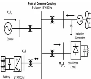
VIII Topology For Power Quality Improvement The STATCOM based current control voltage source inverter injects the current into the grid in such a way that the source current are harmonic free and their phase-angle with respect to source voltage has a desired value. The injected current will cancel out the reactive part and harmonic part of the load and induction generator current, thus it improves the power factor and the power quality. To accomplish these goals, the grid voltages are sensed and are synchronized in generating the current command for the inverter. The proposed grid connected system is implemented for power quality improvement at point of common coupling (PCC), as shown in Fig. 4. The grid connected system in Fig.4, consists of wind energy generation system and battery energy storage system with STATCOM.
A. Wind Energy Generating System
In this configuration, wind generations are based on constant speed topologies with pitch control turbine. The induction generator is used in the proposed scheme because of its simplicity, it does not require a separate field circuit, it can accept constant and variable loads, and has natural protection against short circuit. The available power of wind energy system is presented as under in (8).
Pwind =1/2ρAV³wind (8)
Where p (kg/m) is the air density and A (m2) is the area swept out by turbine blade, Vwind is the wind speed in mtr/s. It is not possible to extract all kinetic energy of wind, thus it extract a fraction of power in wind, called power coefficient Cp of the wind turbine, and is given in (9).
Pmech = CpPwind (9)
Fig4: Grid connected system for power quality improvement.
B. Bess-Statcom
The battery energy storage system (BESS) is used as an energy storage element for the purpose of voltage regulation. The BESS will naturally maintain dc capacitor voltage constant and is best suited in STATCOM since it rapidly injects or absorbed reactive power to stabilize the grid System. It also controls the distribution and transmission system in a very fast rate. When power fluctuation occurs in the system, the BESS can be used to level the power fluctuation by charging and discharging operation. The battery is connected in parallel to the dc capacitor of STATCOM [17]–[21].The STATCOM is a three-phase voltage source inverter having the capacitance on its DC link and connected at the point of common coupling. The STATCOM injects a compensating current of variable magnitude and frequency component at the bus of common coupling.
C. System Operation
The shunt connected STATCOM with battery energy storage is connected with the interface of the induction generator and non-linear load at the PCC in the grid system. The STATCOM compensator output is varied according to the controlled strategy, so as to maintain the power quality norms in the grid system. The current control strategy is included in the control scheme that defines the functional operation of the STATCOM compensator in the power system. A single STATCOM using insulated gate bipolar transistor is proposed to
have a reactive power support, to the induction generator and to the nonlinear load in the grid system. The main block diagram of the system operational scheme is shown in Fig. 5.
Fig 5: System operational scheme in grid system.
IX. Control Scheme
The control scheme approach is based on injecting the currents into the grid using “bang -bang controller.” The controller uses a hysteresis current controlled technique. Using such technique, the controller keeps the control system variable between boundaries of hysteresis area and gives correct switching signals for STATCOM operation.The control system scheme for generating the switching signals to the STATCOM is shown in Fig. 6.
Fig 6: Control system scheme.
A. Grid Synchronization
In three-phase balance system, the RMS voltage source amplitude is calculated at the sampling frequency from the source phase voltage (Vsa Vsb Vsc) and is expressed, as sample template Vsm, sampled peak voltage, as in (11).
Vsm = {2/3(Vsa² + Vsb² + Vsc²)} ½ (11) The in-phase unit vectors are obtained from AC source—phase voltage and the RMS value of unit vector as shown in (12).
Usa = Vsa/Vsm, Usb =Vsb/Vsm, Usc = Vsc/Vsm (12) The in-phase generated reference currents are derived using in-phase unit voltage template as, in (13)
i*sa= I.Usa, i*sb= I.Usb, i*sc = I.Usc (13) Where I is proportional to magnitude of filtered source voltage for respective phases. This ensures that the source current is controlled to be sinusoidal. The unit vectors implement the important function in the grid connection for the synchronization for STATCOM. This method is simple, robust and favorable as compared with other methods [25].
B. Bang-Bang Current Controller
Bang-Bang current controller is implemented in the current control scheme. The reference current is generated as in (14) and actual current are detected by current sensors and are subtracted for obtaining a current error for a hysteresis based bang-bang controller. Thus the ON/OFF switching signals for IGBT of STATCOM are derived from hysteresis controller [26].
The switching function Sa for phase ‘a’ is expressed as (14).
Isa< (isa* - HB) → SA = 0
Isa> (isa* - HB) → SA = 1 (14) Where HB is a hysteresis current-band, similarly the switching function can be derived for phases “b” and “c”.
X. System Performance
The proposed control scheme is simulated using SIMULINK in power system block set. The system parameter for given system is given Table I. The system performance of proposed system under dynamic condition is also presented.
A. Voltage Source Current Control—Inverter Operation
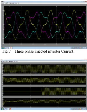
The three phase injected current into the grid from STATCOM will cancel out the
distortion caused by the nonlinear load and wind generator. The IGBT based three-phase inverter is connected to grid through the transformer. The generation of switching signals from reference current is simulated within hysteresis band of 0.08. The choice of narrow hysteresis band switching in the system improves the current quality. The choice of the current band depends on the operating voltage and the interfacing transformer impedance. The compensated current for the nonlinear load and demanded reactive power is provided by the inverter. The real power transfer from the batteries is also supported by the controller of this inverter. The three phase inverter injected current are shown in Fig. 7.
TABLE1
System Parameters
S.N. Parameters Ratings 1 Grid Voltage 3phase,415V,50Hz
2 Induction Motor/Gener
ator
3.35kVA,415V,50Hz,p=4,S peed=1440rpm,Rs=0.01Ω,L s=0.06H,Lr=0.06H
3 Line series Inductance
0.05mH
4 Inverter Parameters
DC Link Voltage=800v,DC Link
Capacitance=100μF,Switchi ng Frequency=2kHz
5 IGBT Rating Collector
Voltage=1200V,Forward Current=50A,Gate Voltage=20V,Power dissipation=310W 6 Load Parameter
Non-Linear Load 25kW.
B. STATCOM - Performance under Load Variations
Fig:7 Three phase injected inverter Current.
Fig 8. (a) Source Current. (b) Load Current.(c) Inverter Injected Current. (d)Wind generator (Induction generator) Current.
The DC link voltage regulates the source current in the grid system, so the DC link voltage is maintained constant across the capacitor as shown in Fig. 9(a). The current through the dc link capacitor indicating the charging and discharging operation as shown in Fig. 9(b).
Fig 9 (a) DC link voltage. (b) Current through Capacitor.
C. Power Quality Improvement
It is observed that the source current on the grid is affected due to the effects of nonlinear load and wind generator, thus purity of waveform may be lost on both sides in the system. The inverter output voltage under STATCOM operation with load variation is shown in Fig. 10.
The dynamic load does affect the inverter output Voltage. The source current with and without STATCOM operation is shown in Fig. 11.
Fig 10. STATCOM output voltage.
Fig.11. Supply Voltage and Current PCC.
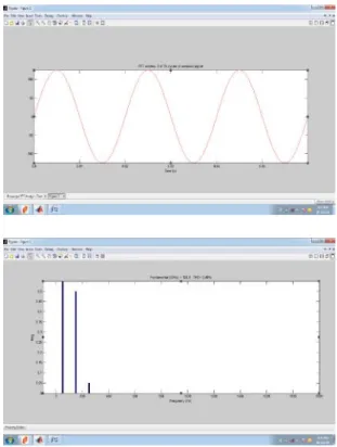
This shows that the unity power factor is maintained for the source power when the STATCOM is in operation. The current waveform before and after the STATCOM operation is analyzed. The Fourier analysis of this waveform is expressed and the THD of this source current at PCC without STATCOM is 4.71%, as shown in Fig. 12.
Fig.12. (a) Source Current. (b)FFT of source current.
operation at 0.7 s and source current waveform is shown in Fig. 13 with its FFT. It is shown that the THD has been improved considerably and within the norms of the standard.
Fig.13. (a) Source Current. (b)FFT of source current.
The above tests with proposed scheme has not only power quality improvement feature but it also has sustain capability to support the load with the energy storage through the batteries.
XI Conclusion
The paper presents the STATCOM-based control scheme for power quality improvement in grid connected wind generating system and with non linear load. The power quality issues and its consequences on the consumer and electric utility are presented. The operation of the control system developed for the STATCOM-BESS in MATLAB/SIMULINK for maintaining the power quality is simulated. It has a capability to cancel out the harmonic parts of the load current. It maintains the source voltage and current in-phase and support the reactive power demand for the wind generator and load at PCC in the grid system, thus it gives an opportunity to enhance the utilization factor of transmission line. The integrated wind generation and STATCOM with BESS have shown the outstanding performance.
Thus the proposed scheme in the grid connected system fulfills the power quality norms as per the IEC standard 61400-21.
References
[1] A. Sannino, “Global power systems for sustainable development,” in IEEE General Meeting, Denver, CO, Jun. 2004.
[2] K. S. Hook, Y. Liu, and S. Atcitty, “Mitigation of the wind generation integration related power quality issues by energy storage,”EPQU J.,
vol. XII, no. 2, 2006.
[3] R. Billiton and Y. Gao, “Energy conversion system models for adequacy assessment of generating systems incorporating wind energy,”IEEE Trans. on E. Conv., vol. 23, no. 1,
pp. 163–169, 2008, Multistate.
[4] Wind Turbine Generating System—Part 21,
International standard-IEC61400-21, 2001.
[5] J. Manel, “Power electronic system for grid integration of renewable energy source: A survey,”
IEEE Trans. Ind. Electron., vol. 53, no. 4,pp.
1002–1014, 2006, Carrasco.
[6] M. Tsili and S. Papathanassiou, “A review of grid code technology requirements for wind turbine,”Proc. IET Renew. Power gen., vol. 3,
pp. 308–332, 2009.
[7] S. Heier, Grid Integration of Wind Energy
Conversions. Hoboken, NJ: Wiley, 2007, pp. 256– 259.
[8] J. J. Gutierrez, J. Ruiz, L. Leturiondo, and A. Lazkano, “Flicker measurement system for wind turbine certification,” IEEE Trans. Instrum.Meas.,
vol. 58, no. 2, pp. 375–382, Feb. 2009.
[9] Indian Wind Grid Code Draft report on, Jul. 2009, pp. 15–18, C-NET.
[10]C. Han, A. Q. Huang, M. Baran, S. Bhattacharya, and W. Litzenberger,“STATCOM impact study on the integration of a large wind farm into a weak loop power system,”IEEE Trans. Energy Conv., vol. 23, no. 1,
pp. 226–232, Mar. 2008.
[11] D. L. Yao, S. S. Choi, K. J. Tseng, and T. T. Lie, “A statistical approach to the design of a dispatchable wind power—Battery energy storage system,”IEEE Trans. Energy Conv., vol. 24, no. 4,
Dec. 2009.
Ms.Badvelu Gayathri Was born in Andhra Pradesh, India. She received the B.Tech degree in Electrical and Electronics Engineering from JNT University, Anantapur in 2012 and Pursuing M.Tech degree in Electrical
Power Systems from JNT
University, Anantapur. She completed her B.Tech degree in Geethanjali Institute of Science and Technology and M.Tech degree in Audisankara College of Engineering and Technology, Gudur, AP.
Mr.M.NAGARAJU was born in Andhra Pradesh, India .He received the B.Tech degree in Electrical and Electronics Engineering from JNT University, Hyderabad in 2002 and M.Tech degree in Electrical Power Systems from JNTUniversity Ananthapur in 2008. He is currently pursuing the Ph.D. degree at the JNT University, Hyderabad, Andhra Pradesh, India.He had worked as an Assistant professor in the Dept of EEE in
N.B.K.R.I.S.T Vidyanagar.Worked as