The Basic Study of Underwater Robot Control for Over Actuated Systems
Keon Seok Nam, Dong Gu Lee, Je Doo Ryu, Kyoung Nam Ha
*Robot Center, Korea Institute of Industrial Technology, Busan, Korea
Received 14 May 2018; received in revised form 30 May 2018; accepted 16 July 2018
Abstract
In general, only six individual thrusters are required to perform 6 DOF (Degree Of Freedom) motion.
Sometimes, however, more than six thrusters are used for 6 DOF motion for a variety of purposes. The over actuated
systems can transit quickly from transient state caused by disturbance to steady state through the over actuated input.
So in the underwater robot, the purpose of over actuated system is mainly used to maintain stable motion and
position. And that systems are performed to obtain the optimal efficiency through the thruster force distribution. In
this paper, we designed and fabrication the ROV (Remotely Operated Vehicle) for the basic study of over actuated
underwater robot. It has 4 horizontal thrusters and 4 vertical thrusters. Using this system, we derived the thruster
force distribution matrix for thruster allocation. Also, to check the kinetic characteristics of over actuated underwater
robot before applying various controller, we performed the basic motion performance test and motion control test
using the PD controller in the indoor engineering water basin.
Keywords: over actuated system, ROV, motion control, 6 DOF
1.
Introduction
Various types of underwater robots are being used for exploration, inspection and operation in underwater environments.
For efficient exploration, inspection, and operation, it is necessary to develop and use equipment that is suitable for the purpose.
Generally used underwater robot are divided into AUV (Autonomous Underwater Vehicle) capable of autonomous operation
and ROV(Remotely Operated Vehicle) operated by operators. The AUV shown in Fig. 1, it is capable of performing specific
tasks through autonomous navigation without having a separate tether and operator, but it can not acquire real-time captured
images and underwater exploration information. The ROV shown in Fig. 2, it is operated by the operator through the tether in
the separate surface ship, and has the feature to check the images and data acquired in real time. Therefore, ROV is generally
used for inspection, construction and maintain for underwater structure.
When an underwater robot is used to carry out specific tasks, one operator may operate the entire underwater robot, but
this is very limited in various underwater tasks. It is mainly divided into two operators. One operate the underwater robot body
and the other operators the underwater robot's manipulator. In the task, there are many cases in which the underwater robot
body must maintain a specific position and attitude, and the operator can directly control the motion. However, because of the
disturbance occurring in the underwater environment such as the current, It is difficult for unskilled operators to react
immediately.
In order to control the 6 DOF motion of a general underwater robot, it is possible to control the translational and rotational
motion of each axis by using six thrusters. However, there are cases where an over actuated system is constructed using several
thrusters so that the motion control can be efficiently performed even if disturbance acts in the underwater environment.
In this paper, we design ROV of an over actuated system that controls 6 DOF motion by using a number of the thruster,
and it is a basic study to implement auto pilot function that can help operator 's convenience by using it. The configuration of
the paper consists of the design and configuration of the underwater robot, the coordinate system setting of the underwater
robot, the design of the attitude controller, the attitude control test in the engineering water basin, and the conclusion.
Fig. 1 Torpedo type AUV [1]
Fig. 2 Observation class ROV [2]
2.
Design and Configuration
(a) The outline of underwater robot (b) The thrusters and pressure vessels arrangement
Fig. 3 illustration of designed underwater robot
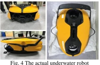
Fig. 4 The actual underwater robot
The underwater robot consists of the sensors, external frame, inner frame, and pressure vessel. The shape of the
underwater robot is designed as a droplet shape to reduce the resistance of the fluid. In addition, to minimize the weight and
in Fig. 3(a). Designed underwater robot, the maximum operational depth is 300 m and operation depth is 200 m. As shown in
Fig. 3(b), four vertical thrusters and four horizontal thrusters are used, and the arrangement of the vertical thruster is installed
symmetrically on the left and right, front and rear. The horizontal thrusters are arranged at 45 degree angles to obtain the vector
type thrust and two each are installed symmetrically on the front and rear section [3]. The types of sensors attached are DVL
(Doppler Velocity Log), AHRS (Attitude and Heading Reference System), 2D Image Sonar, and HD-camera. The actual
underwater robot is shown in Fig. 4
3.
Coordinate System
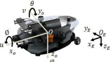
In order to present the attitude and position of the underwater robot, we set the coordinate system as in Fig. 5. We used
two kinds of coordinate system. One is the body fixed coordinate system and the other is earth fixed coordinate system. The
origin of the body fixed coordinate system is located in the geometric center of the underwater robot body. The front of
underwater robot body direction is defined as the X-axis and depth direction is defined as the Z-axis. The Y-axis direction is
determined by the right-handed coordinate system. In addition, the Earth fixed the coordinate system for expressing the attitude
and position of the underwater robot is a NED coordinate system in which the north axis is the X-axis, the water depth direction
is the Z-axis, and the east axis is the Y-axis [4].
Fig. 5 Coordinate system of underwater robot
4.
Motion Controller
The controller of over actuated system achieves the control purpose by finding an efficient thrust distribution method.
Generally, for thrust distribution, a thrust allocation matrix is used. It can be obtained via kinematic analysis. In this study, as a
basic study before the thrust allocation control of over actuated system, the pitch angle and the depth position control were
performed using symmetric thrusters to confirm the dynamic characteristic. The controller was used a PD controller and the
control formula is as follows (1) [5].
D
( )
p( )
de
u t
K e t
K
dt
(1)5.
Test in the Engineering Water Basin
(a) Wave basin (b) Current generating basin
The experiment was carried out in the engineering water basin to confirm the motion characteristics of the designed
underwater robot. It was carried out at the Marine Robot Center in the Korea Institute of Industrial Technology. The dimension
of the wave basin is 5 m length, 2 m width, and 9 m depth. Also, the dimension of the current generating basin is 22 m length,
3.5 m width and 3 m deep. The actual engineering water basin is shown in Fig. 6.
In case of inspection and operation of the general underwater robot, they usually work hovering at the specific depth. In
order to confirm the motion characteristics at the hovering motion, using only the 4 vertical thrusters, the pitch angle and depth
control were performed as shown in Fig. 7. The pitch angle was controlled by two forward and rear thruster among the four
vertical thruster, and the depth control was carried out using two thruster on the left and right. The desired value of the pitch
angle control was set to 20 degrees, and the desired value of the depth control was set to maintain at 1 m. Fig. 8 shows the
attitude angle (Roll, Pitch, Yaw) of the underwater robot, which is changed due to the rotation of each axis. Also, Fig. 9 shows
the position in the depth direction. As can be seen in Fig. 8 (b), it can be confirmed that the attitude was maintained about -17
degrees at 10 seconds. Also, as shown in Fig. 9, although the depth of 1 m was maintained, oscillation occurs at about 10
seconds, and after reaching the desired depth at 20 seconds, it is maintained about 0.8 m.
Fig. 7 The motion test of underwater robot
(a) Roll angle (b) Pitch angle (c) Yaw angle
Fig. 8 The attitude of underwater robot
Fig. 9 The Z-position of underwater robot
6.
Conclusions
We designed and fabricated an underwater robot used a number of the thruster for vector thrust. Also, pitch and depth
distribution of the multiple thrusters to generate the vector thrust. As shown in the previous section, the pitch control shows a
difference of about 3 degrees from the desired value, and the depth control is maintained between 0.7 m and 1.0 m. This is
expected to result in a steady state error resulting from the I controller being excluded from the PD controller. Also, it can be
seen that the oscillation occurring at about 10 seconds during the depth control is caused by the rapid change of the pitch angle,
which appears to occur by using independent controllers that do not consider the relationship between pitch angle and depth
control.
In the future, it is planned to set the constraints for optimal control of the over actuated system using multiple thrusters,
and to perform attitude / position control using the thrust allocation matrix.
Conflicts of Interest
The authors declare no conflict of interest.
References
[1] B. He, B. R. Wang, T. H. Yan, and Y. Y. Han, “A distributed parallel motion control for the multi-thruster autonomous underwater vehicle,” Mechanics Based Design of Structures and Machines, vol. 41, no. 2, pp. 236-257, February 2013. [2] R. D. Christ and R. L. Wemli Sr, The ROV manual:a user guide for remotely operated vehicles, 2nd ed.
Butterworth-Heinemann, 2013.
[3] T. I. Fossen, T. A. Johansen, and T. Perez, A survey of control allocation methods for underwater vehicles, InTech, pp. 109-128, 2009.
[4] T. I. Fossen, Guidance and control of ocean vechicles, New York: John Wiley & Sons Inc, September 1994. [5] D. H. Kim, Redundancy resolution and robust controller design for dynamic stability enhancement of underwater
vehicle-manipulator systems, Doctorate Thesis, Korea, Graduate School of Department of Mechanical Engineering, 2016.
Copyright© by the authors. Licensee TAETI, Taiwan. This article is an open access article distributed under the terms and conditions of the Creative Commons Attribution (CC BY-NC) license