Available Online At www.ijpret.com
INTERNATIONAL JOURNAL OF PURE AND
APPLIED RESEARCH IN ENGINEERING AND
TECHNOLOGY
A PATH FOR HORIZING YOUR INNOVATIVE WORKSYNCRONIZATION METHOD FOR CARRIER FREQUENCY OFFSET IN OFDM
MEGHASHREE D. NIMJE, A. P. RATHKANTHIWAR
Priyadarshini College of Engineering, Nagpur, (M.S)
Accepted Date:
27/02/2013
Publish Date:
01/04/2013
Keywords
Microstrip Transmission
Line
Ultra Wide Band
Planar Antenna
Corresponding Author
Ms. Meghashree D. Nimje
Abstract
Research Article ISSN: 2319-507X Meghashree Nimje, IJPRET, 2013; Volume 1(8):477-485 IJPRET
Available Online At www.ijpret.com
INTRODUCTION
OFDM is the multipath Modulation
system(MCM).It uses FFT Fast fourier
transformer and IFFT inverse fourier
transformer. In single carrier system signal
representing each bit uses all of the
available spectrum. Orthogonal frequency
division multiplexing (OFDM) is an effective
transmission scheme to combat multipath
fading. The fading is frequency flat and
there is no inter symbol interference in time
domain.. It is a parallel transmission
scheme. ,which divides available bandwidth
into many narrow bands like ~2000-8000
for digital TV ~48 for Hiperlan 2.Data is
transmitted in parallel on these bands. Data
is transmitted in parallel on these bands the
basic principal of OFDM is .there a
mathematical relationship between the
subcarriers .In OFDM ,each subcarriers has
exactly an integer number of cycles in the
FFT interval. The number of cycles between
the adjacent subcarriers differs by exactly
one.
Ofdm is very popular technique because
most broadband systems are subject to
multipath transmission. The conventional
solution to multipath is an equalizer in the
receiver side. But high data rates -
equalizers are too complicated..Ofdm is the
simple way of equalizer problem.
Main problem of OFDM is the
synchronization in terms of frequency
offset. OFDM is highly sensitivity to
frequency offset errors which damages
orthogonality among subcarriers. Various
effect of OFDM is that it decrease the
amplitude of each sampled value and
introduction of
intercarrierinterference(ICI).Therefore,
Carrier frequency offset (CFO)estimation in
OFDM systems is essential to improve
communication system performance.
CFO can be estimated in two steps ,first find
the integer CFO and then find the fractional
CFO. Integer CFO Causes a cyclic shift of
subcarriers and a phase change
proportional to the OFDM symbol number.
This needs to be corrected perfectly.
Fractional CFO Attenuates the desired
signal, adds phase, and causes an
inter-carrier interference (ICI),reduces the signal
to noise ratio (SNR),increases the bit error
rate (BER).Many methods for carrier
Available Online At www.ijpret.com II OFDM SYSTEM MODEL
Various operation s are performed in
transmitter as shown in fig 1.
Fig (1) OFDM Transmitter
The mapping the information bits onto the
signal plays a important role in determining
the properties of the modulation. An
OFDM signal is a sum of sub
of which contains phase shift
or(QAM) quadrature amplitude modulated
signals.
After the signal generated at transmitter
side it transmit through the channel .At
receiver side serial to parallel conversion is
done, as shown in fig2. In a conventional
serial data system, the symbols are
transmitted serially, the frequency
spectrum of each data symbol allowed to
occupy the entire available bandwidth.
Several adjacent symbols may be
completely distorted over frequency
selective fading when the data rate is
sufficient high. A small part of available
bandwidth is normally occupied by the
Available Online At www.ijpret.com
Various operation s are performed in
itter as shown in fig 1.
The mapping the information bits onto the
signal plays a important role in determining
the properties of the modulation. An
OFDM signal is a sum of sub-carriers, each
of which contains phase shift keyed (PSK)
or(QAM) quadrature amplitude modulated
After the signal generated at transmitter
side it transmit through the channel .At
receiver side serial to parallel conversion is
In a conventional
e symbols are
transmitted serially, the frequency
spectrum of each data symbol allowed to
occupy the entire available bandwidth.
Several adjacent symbols may be
completely distorted over frequency
selective fading when the data rate is
mall part of available
bandwidth is normally occupied by the
spectrum of an individual data element.
an entire channel bandwidth is divided into
many narrow subbands, the frequency
response is relatively flat over each
individual subchannel. A paralle
transmission system offers solution to this
problem .
Fig (2 )OFDM Receiver
OFDM system as shown in fig 3 has cyclic
prefix added at transmitter side and
removal of cyclic prefix at receiver side. For
the purpose to eliminate the effect of I
the guard interval or cyclic prefix is used in
OFDM systems to combat against multipath
fading. IDFT and DFT units are used at
transmitter and receiver side to reduce the
complex calculation of modulation and
demodulation.
spectrum of an individual data element. As
an entire channel bandwidth is divided into
many narrow subbands, the frequency
response is relatively flat over each
individual subchannel. A parallel
transmission system offers solution to this
Fig (2 )OFDM Receiver
OFDM system as shown in fig 3 has cyclic
prefix added at transmitter side and
removal of cyclic prefix at receiver side. For
the purpose to eliminate the effect of ISI,
the guard interval or cyclic prefix is used in
OFDM systems to combat against multipath
fading. IDFT and DFT units are used at
transmitter and receiver side to reduce the
Research Article ISSN: 2319-507X Meghashree Nimje, IJPRET, 2013; Volume 1(8):477-485 IJPRET
Available Online At www.ijpret.com
Fig( 3)OFDM system
(i) OFDM SIGNAL GENERATION
Here we represent the OFDM system
implemented by Inverse fast Fourier
Transform (IFFT) and Fast Fourier Transform
As shown in fig 1 and in fig 2. Here the data
is transmitted in parallel that is N parallel
streams .Now the parallel data is converted
into serial data .Cyclic Prefix(CP) is added to
avoid residual Inter symbol interference
(ISI).Parallel data are used as inputs to an
IFFT.IFFT output is the sum of signal
samples. Modulation and multiplexing is
done in one step by IFFT. At receiver side
FFT then CP removal is performed. Finally
conversion of digital to analog results in
baseband signal.
OFDM Signal at receiver are as follows:
Fig(4) Result of OFDM signal at receiver
Due to Doppler shift [4]and instabilities at
the transmitter and receiver oscillators
carrier frequency offset(CFO) occurs in
OFDM system. This carrier frequency offset
causes degradation of the systems
performance as it increase the noise level in
the system.CFO also result in introduction
of Inter Carrier Interference.
This paper discuss the carrier frequency
offset estimation method to improve the
system’s performance.
III. RELATED WORK TO ESTIMATE CARRIER
FREQUENCY OFFSET
An improved method to deal with both
IFO(integer frequency offset) and
FFO(fractional frequency offset) estimation
problems is presented by T. M. Schmid [7].
A training sequence with two OFDM
symbols are used. The fractional part
ranged between 1/ s − NT and 1/ s NT . The
first symbol whose first half is identical to
the second half is use to estimate Fractional
frequency offset in time domain. Using
differential information of the two symbols
an auxiliary sequence is constructed. Then
frequency-domain correlation is carried out
Available Online At www.ijpret.com
Other related work in OFDM system[4], to
estimate frequency offset is use of cyclic
prefix(CP). CP always exists in OFDM symbol
and using CP can be simply designed to
auto-correlation. Also auto-correlation is
usable irrespective of data contents and
modulation schemes. Accordingly using CP
for auto-correlation is widely used to
estimate frequency offset.
However this auto-correlation method has
an undesirable defect. The defect is that the
method cannot precisely estimate Doppler
frequency.
In conventional method to estimate the
carrier frequency offset, two repetitive
training symbols are used and then
compare of the phases between the
successive identical symbols is a simple,
useful technique, which was first proposed
in 1994 by P.H.Moose.[3]. This method
gives the simple correlation of two identical
signals to find the Signal to Noise ratio
(SNR) and Bit error ratio (BER).
In this method the phase variation between
the two identical OFDM symbols is
observed, at the receiver side the frequency
offset can be estimated within the range of
half a subcarrier spacing. Because each
subcarrier is shifted in frequency by a
constant amount of 2πЄ/N, due to offset
,where Є is frequency offset and N are the
samples. Here the acquisition range for
Fractional frequency offset is limited due to
correlation length N is equal to the
subcarrier number. Solution to this is to use
training sequences with smaller N . But that
result in less estimation accuracy. The
disadvantages of this method are it uses
two symbol and estimation range is less
than half subcarrier spacing .Other problem
is of security since the repetitive structure
may be used by undesired users.
IV CARRIER FREQUENCY OFFSET
ESTIMATION METHOD
In this method carrier frequency offset
estimation is done in two ways
1. Integer carrier frequency offset
estimation.
2. Fractional frequency estimation.
Fractional frequency offset and the integer
frequency offset both damages
orthogonality among subcarriers.
Research Article ISSN: 2319-507X Meghashree Nimje, IJPRET, 2013; Volume 1(8):477-485 IJPRET
Available Online At www.ijpret.com
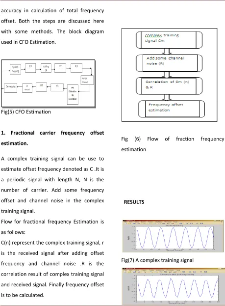
accuracy in calculation of total frequency
offset. Both the steps are discussed here
with some methods. The block diagram
used in CFO Estimation.
Fig(5) CFO Estimation
1. Fractional carrier frequency offset
estimation.
A complex training signal can be use to
estimate offset frequency denoted as C .It is
a periodic signal with length N, N is the
number of carrier. Add some frequency
offset and channel noise in the complex
training signal.
Flow for fractional frequency Estimation is
as follows:
C(n) represent the complex training signal, r
is the received signal after adding offset
frequency and channel noise .R is the
correlation result of complex training signal
and received signal. Finally frequency offset
is to be calculated.
Fig (6) Flow of fraction frequency
estimation
RESULTS
Available Online At www.ijpret.com
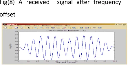
Fig(8) A received signal after frequency
offset
Fig (8) A cross correlation of complex signal
&received signal.
Integer carrier frequency offset estimation
After FFT, use frequency domain pilot to
estimate the integer frequency offset. If the
fractional frequency can be corrected the
only integer frequency offset has to
calculate.The correction range is |m| < N/2.
Total frequency offset can be estimated as
the sum of fractional frequency & integer
frequency.
V. CONCLUSIONS
In conventional method only integer
frequency offset is estimated in frequency
domain. Estimation range is limited. This
method can effectively estimate course and
fine frequency offset in OFDM system. It
can effectively improve the frequency
estimation accuracy. The frequency offset
can estimate very closely with wide range
which will improve the system performance
to a large extent It provides a wide
acquisition range for the carrier frequency
offset with low complexity. Instead of using
the training signals, the complex signal can
reduce the overhead
REFERENCES
1. Tangdi Zhang, Caixiang Wang and
XiaowenLi” Frequency Offset and Channel
Estimation in OFDM Systems by
BlindAdaptiveFilter” School of
Communication and Information
Engineering Chongqing University of Posts
and Telecommunications Chongqing, China.
IEEE 978-1-4244-9003-5/10/2010.
2. Min Ho Jin, Young Min Cho, Janghoon
Yang, Dong Ku Kim, “Pilot aided carrier
frequency offset estimation for OFDM
systems,” IEEE Signal Processing and
Communication Systems, pp. 1–6, April
2009.
3. PH Moose,” A technique for orthogonal
frequency division multiplexing frequency
offset correction," IEEE Trans. Commu.
vol.42, no. 10, pp. 2908-2914, 1994.
4. “Doppler Frequency Offset Estimation in
Research Article ISSN: 2319-507X Meghashree Nimje, IJPRET, 2013; Volume 1(8):477-485 IJPRET
Available Online At www.ijpret.com
Hyoungjun Park Mobile Telecommunication
research Division, ETRI.IEEE 2009.
5. Blind Adaptive Scheme for Joint
Frequency Offset and Channel Estimation
in OFDM system” Tangdi Zhang, Caixiang
Wanand Xiaowen Li School of
Communication and Information
Engineering.2010 2nd International
Conference on Signal Processing Systems.
6. An Efficient Algorithm for Joint Carrier
Frequency Offset and Channel Estimation
in IEEE 802.16 OFDM systems” Balamurali.
N Telecommunications and Networking
Group, Indian Institute of Technology,
Madras
7. T. M. Schmidl and D. C. Cox, "Robust
frequency and timing synchronization for
OFDM," IEEE Trans. Commu., vol. 45, no.
12, pp. 1613-1621, 1997
8. Carrier Frequency Offset Estimation for
OFDM Systems Using Null Subcarriers”
Defeng (David) Huang, Member, IEEE, and
Khaled Ben Letaief, Fellow, IEEE2006 IEEE
814 IEEE transaction on communications,