저작자표시-비영리-변경금지 2.0 대한민국 이용자는 아래의 조건을 따르는 경우에 한하여 자유롭게 l 이 저작물을 복제, 배포, 전송, 전시, 공연 및 방송할 수 있습니다. 다음과 같은 조건을 따라야 합니다: l 귀하는, 이 저작물의 재이용이나 배포의 경우, 이 저작물에 적용된 이용허락조건 을 명확하게 나타내어야 합니다. l 저작권자로부터 별도의 허가를 받으면 이러한 조건들은 적용되지 않습니다. 저작권법에 따른 이용자의 권리는 위의 내용에 의하여 영향을 받지 않습니다. 이것은 이용허락규약(Legal Code)을 이해하기 쉽게 요약한 것입니다. Disclaimer 저작자표시. 귀하는 원저작자를 표시하여야 합니다. 비영리. 귀하는 이 저작물을 영리 목적으로 이용할 수 없습니다. 변경금지. 귀하는 이 저작물을 개작, 변형 또는 가공할 수 없습니다.
Master's Thesis
PAPR Reduction in GFDM Systems
Using an SLM Technique
Hyunmyung Oh
Department of Electrical Engineering
Graduate School of UNIST
2017
PAPR Reduction in GFDM Systems
Using an SLM Technique
Hyunmyung Oh
Department of Electrical Engineering
Abstract
In the fifth generation (5G) cellular network system, user capacity should be improved com-pare with the current 4G network system. To this end, higher resource efficiency is an essential. Orthogonal frequency division multiplexing (OFDM) and orthogonal frequency division mul-tiple access (OFDMA), which has high spectral efficiency resorting to orthogoanlity between subcarriers, is the most commonly used modulation technique in the current 4G network sys-tem. To maintain orthogonality, several types of frame structures are used for synchronized signal transmission and reception in Long Term Evolution (LTE). However, these fixed frame structures result in a fundamental limit for reducing latency. Thus an asynchronous commu-nication scheme has been emerged as one of the solutions to reduce latency. On the contrary, without synchronization, OFDM signals generate interference to each other. Recently, general-ized frequency division multiplexing (GFDM) has been proposed for the asynchronous multiple access. Many studies have evaluated that GFDM has higher sum-rate than OFDM for the asyn-chronous systems owing to the higher spectral efficiency and lower out-of-band emission (OOB). Despite the many advantages, GFDM also has disadvantages such as a high peak-to-average power ratio (PAPR). If the numbers of GFDM and OFDM subcarriers are equal, GFDM will get higher PAPR than OFDM due to multiple subsymbols. To reduce the PAPR, various PAPR reduction techniques have been studied on OFDM such as clipping, selective mapping (SLM), partial transmit sequence (PTS), Tone reservation (TR), and single-carrier frequency division multiple access (SC-FDMA) for LTE uplink. In GFDM, precoded GFDM and generalized fre-quency division multiple access (GFDMA) have been proposed as PAPR reduction techniques. Among PAPR reduction techniques, SLM is one of applicable techniques to the GFDM without signal distortions. In this paper, GFDM SLM is proposed as a PAPR reduction technique. In addtion, the performance analysis is compared in terms of the PAPR, OOB, and spectral efficiency among SC-FDMA, OFDMA, GFDMA, precoded GFDM, and GFDM SLM.
Contents
1 INTRODUCTION 7
2 BACKGROUND 8
2.1 OFDM System Model . . . 8
2.2 PAPR . . . 11
2.2.1 Definition and general effect of PAPR in OFDM systems . . . 11
2.2.2 Theoretical estimation of OFDM PAPR . . . 12
2.3 OFDM PAPR Reduction Schemes . . . 12
2.3.1 Clipping . . . 12
2.3.2 Selective mapping and partial transmit sequence . . . 13
2.3.3 Tone reservation . . . 13
2.4 SC-FDMA System Model . . . 14
2.5 GFDM . . . 16 3 RELATED WORK 18 3.1 GFDMA . . . 18 3.2 Precoded GFDM . . . 19 4 CONCEPT OF GFDM SLM 21 5 PERFORMANCE ANALYSIS 23 5.1 Performance Evaluation of PAPR . . . 23
5.2 Spectrum Analysis . . . 25
5.3 Spectral Efficiency . . . 26
List of Figures
1 The major benefits of PAPR reduction for the power amplifier of OFDM transmitters. 11
2 Block diagram of iterative clipping and filtering . . . 13
3 Block diagram of OFDM SLM . . . 14
4 Block diagram of OFDM PTS . . . 14
5 Subcarrier distribution for each user in LFDMA and IFDMA (K=9,Kuser=3) . . . . 15
6 PAPR of LFDMA and IFDMA . . . 16
7 Spectrums of LFDMA and IFDMA . . . 16
8 Block diagram of GFDM from [12] . . . 17
9 Block diagram of GFDM from [13] . . . 18
10 spectral efficiency of GFDM vs OFDM in the asynchronous system . . . 19
11 Sum rate of GFDMA vs SC-FDMA in the asynchronous system . . . 20
12 PAPR of SC-FDMA and GFDMA . . . 21
13 The spectrum of OFDMA, SC-FDMA, GFDM, and GFDMA . . . 22
14 Block diagram of DFT precoded GFDM . . . 22
15 Block diagram of basic GFDM SLM . . . 23
16 Block diagram of simplified GFDM SLM . . . 23
17 PAPR of simulations and theoretical estimations. (a) OFDM SLMK = 128, β= 2.3, (b) GFDM SLM K= 128, M = 5, α= 2.8and a = 0.5 . . . 24
18 PAPR of simulations and theoretical estimations with different parameters . . . 25
19 PAPR comparison of GFDM SLM, GFDMA and SC-FDMA. . . 26
20 PAPR comparison of GFDM SLM and precoded GFDM. . . 27
21 Spectrum of PAPR reduction techniques. . . 28
List of Tables
1 PAPR of OFDM comparison for different modulations (at γ = 0.01) . . . 12
2 Parameters for DL OFDMA and UL SC-FDMA transmission . . . 15
3 OFDM SLM, GFDM SLM and SC-FDMA system parameters . . . 24
4 Interference to adjacent user as guard subcarriers . . . 26
Nomenclature
3GPP
3rd Generation Partnership Project
BW
bandwidth
CP
cyclic prefix
DFT
Discrete Fourier transform
FDMA
frequency-division multiple access
FFT
Fast Fourier transform
GFDM
Generalized Frequency Division Multiplexing
GFDMA
generalized FDMA
ICI
intercarrier interference
IFDMA
interleaved SC-FDMA
IFFT
Inverse Fast Fourier transform
ISI
Intersymbol Interference
LFDMA
localized SC-FDMA
LTE
long term evolution
LTE-A
LTE-Advanced
MIMO
Multiple-input and multiple-output
OFDM
Orthogonal frequency-division multiplexing
OFDMA
Orthogonal frequency-division multiple access
PAPR
Peak-to-Average Power Ratio
PSK
phase shift keying
QAM
quadrature amplitude modulation
SC-FDMA Single-carrier FDMA
SLM
Selective mapping
1
INTRODUCTION
In the 5G network systems, there are several topics to achieve, such as massive MIMO, machine-to-machine communication, millimeter wave, ultra-dense network and ultra-low latency communica-tion. The success and failure of topics are definitely related the developments on the user capacity, data rates, delay performance, and applications. Therefore, compared with the current 4G sys-tem, the importance of lower latency and resource efficiency are much emphasized in the upcoming 5G mobile network system [5]. The guideline of 5G proposed by some research groups. Among them, there are two main project groups. One is the METIS 2020 project. The METIS has pro-posed applications such as device-to-device communication, ultra-dense network, and ultra-reliable communications [32]. An other research project is 5GNow. Internet of things, gigabit wireless con-nectivity, and tactile internet are target applications of the 5GNow . Among the reseach projects, 5GNow has focused on non-orthogonal, asynchronous communication for an unifed frame structure concept [43,44].
OFDM is a muticarrier modulation scheme using orthogonal subcarriers. It has attractive ad-vantages such as high frequency efficiency, low interference of subcarriers to each other, elimination of ISI by the CP, and narrow band experiences [9]. For this reason, OFDM has been used on various standards such as digital video broadcasting (DTV), digital audio broadcasting (DAB), worldwide interoperability for microwave access (WiMAX), Wi-Fi, LTE, and LTE-A [14,16]. However, to keep the orthogonality, OFDM needs to be synchronized between users and an enhanced Node B(eNB) in both time and frequency domain [21,37]. In the current 4G network system, several frame structures are used for the synchronized transmission. Either time division duplex (TDD) or frequency division duplex (FDD), needs to wait available time slot to transmit a signal [2]. According to 3GPP ITU-R document, the latency is about 10ms assuming connected transmission in the 4G LTE system. The delay can be enlarged as increasing user density due to the limited time-frequency resource and waiting time on resource allocation [39]. It means an asynchronous communication system could be one of the solutions for decreasing the latency of current LTE system. This is the reason why 5GNow emphasized the necessity of asynchronous systems [43].
Another topic is new wavform designs for high spectral efficiency. In asynchronous environments, loss of orthogonality is a reason of high ICI because of large OOB of OFDM. To solve this problem, several analysis and solutions have been represented [4, 18, 23]. Among these, 5GNow has focused on waveform designs, introduced following four waveform designs, filtered OFDM, filter band based multicarrier, universal filtered multi-carrier, and GFDM with performance analysis [7, 24, 25, 46]. GFDM is one of a new wave form design as an alternative to the asynchronous and non-orthogonal environments which is proposed by Professor G. Fettwis. GFDM is possible to use CP like OFDM and as parameter setting, completely compatible to current synchronized OFDM systems. A sub-symbol concept of GFDM makes possible to reduce OOB, thus more suitable condition for an asynchronous system than OFDM [12,27].
On the other hand, the power is one of considerable problems. High PAPR is a performance factor related with increasing of circuit build cost and a distortion of signals owing to non-linearity. It is caused by transmitted, received power and modulation. Basically, OFDM has high PAPR because of it’s superposition of subcarriers. Therefore, the methods of reducing PAPR have been proposed up to now such as clipping [22], SLM and partial transmit sequence (PTS) [10, 17, 28]„ and tone reservation [19]. In the current 4G LTE, OFDMA [36] and SC-FDMA [29] are universal modulations for uplink and downlink. OFMDA is based on OFDM, but a difference is consideration about other user’s subcarriers at once. In the same side, SC-FDMA is considered for multiuser environments. The main purpose of SC-FDMA is focused on uplink scenarios with low PAPR signal transitions [2]. Therefore, those two modulation techniques are standard of performance analysis of PAPR and spectral efficiency.
The main theme of thesis is the PAPR reduction of GFDM using a SLM technique. SLM does not change subsymbol carrier waveform designs such as raised cosine (RC) or root raised cosine (RRC). Many OFDM SLM techniques have been researched, but GFDM. In addtion, because of the similarity between OFDM SLM and GFDM SLM, SLM is suitable for applying to GFDM. In this thesis, theoretical expectation for GFDM SLM will be estimated according to the estimation of OFDM SLM. From simulations of GFDM SLM, proper compensation constants are also represented. Finally, PAPR and spectral efficiency are compared among the current major modulations and GFDM SLM.
The composition of the paper is as follows. In Section II, detail backgrounds are describes basic concepts which definition of PAPR, basic concept and the system models of OFDM, GFDM, and SC-FDMA. Some of recently proposed GFDM PAPR reduction will be discussed in Section III. A concept of proposed GFDM SLM is described in Section IV. Section V shows performance analysis between modulations. Section VI is end of main contents, conclusion.
2
BACKGROUND
2.1 OFDM System Model
OFDM is a major modulation in current communication systems like cellular network and Wi-Fi. OFDM has significant number of advantages to use such as high spectral efficiency, frequency selec-tive channel and CP. Those advantages come from two key concepts. One is multicarrier, another one is orthogonality. Compare with single carrier modulation, several subcarriers are modulated at once in OFDM. OFDM subcarriers are orthogonaly distributed, for higher frequency band efficiency. Also, it makes less interference between ICI than the single carrier modulation. The narrow band signal of OFDM is a same context. For understanding about a system model of OFDM , first, an OFDM system usesK subcarriers is considered. Each subcarrier is matched to thek= 0 toK−1
data symbol array which is same as an index of the subcarriers. The array of data symbol d(k), is
Fourier transform x(t) = K−1 X k=0 d(k)ej2πkMf t (1)
where 4f is difference between subcarriers, T is one OFDM symbol duration, 0≤t≤T. k-th
subcarrier can be noted by fk = k4f. Then, the subcarriers of OFDM are orthogonal to other subcarriers like (2). Z t=T t=0 (ej2πkMf t)∗ej2πlMf t= T l=k 0 l6=k (2)
Due to the orthogonality, OFDM can be represented by inverse DFT (IDFT) or IFFT. The time domain sampling can be assumed by Mf = 1/T. Thus, (1) is equal to (3) forN,assumedn= 0 to N −1. x[n] = √1 K K−1 X k=0 d(k)ej2πk n/N (3) √
K is normalize factor, andN =K. Then (3) is same as a multiplication of IFFT matrix and
the data symbol vector, (3) can be written by
x=FHNd (4)
whereFNHis aN×N IFFT matrix. H means Hermitian [21,37].
When a receiver gets the transmitted signal x, the signal is changed by a channel. If an LTI
system and a multipath channel is assumed, the received signaly is extended by a multipath
prop-agation. The transmittedxwill be ISI to another OFDM symbols which are just after transmitted.
The impulse response of multipath propagation is represented by
h(t, τ) = Ntap X
i=1
ci(t)δ(τ −τi) (5)
whereτi is a delay ofi-th multipath,ci(t) means a complex amplitude of each impulse response. To solve this problem, a guard time is placed between each transmission. However, the guard time is inefficient to use time resources. The CP is a solution for the ISI and time inefficiency of the guard time. In OFDM system, (5) can be assumed by
h= [h0,h1,h2, ,hNtap−1]
T (6)
where hi ∈C. Then the received signal is noted by y=h∗x, where∗ is convolution. Then(6)
y=Hx= y0 y1 ... yN+Ncp−2 = h0 0 0 h1 h0 ... ... ... ... hNtap−1 hNtap−2 h0 0 hNtap−1 ... ... hNtap−2 0 0 · · · 0 hNtap−1 x0 x1 ... xN−1 (7)
From (7), a CP is added which is a last part of xto the beforex. After removing the additional
added parts,His change to a circulant matrix Hcpandy is represented by (8).
y=Hcpx= y0 y1 ... yN−1 = h0 0 · · · hNtap−1 hNtap−2 · · · h1 h1 h0 · · · 0 hNtap−1 · · · h2 ... ... ... ... hNtap−1 hNtap−2 0 0 hNtap−1 · · · 0 ... ... 0 0 · · · h0 x0 x1 ... xN−1 (8) By multiplying an FFT matrix, the circular matrixHcp is decomposed by singular value
decom-position (SVD). Then the channel frequency response is digonalized [11]. The channel frequency response can be detected by pilot, based on detected channel response, the data is able to estimate. The basic concept of OFDMA is distribute the BW to multiple users using OFDM. The users are synchronized by LTE frame structures. In downlink, each user knows the assigned own frequency BW and time slot from resource block. Therefore, they can get their own data from the received signal. In uplink, the synchronized users are transmit data to eNB. For more elaborate transmission, some techniques are used like time advanced [3]. In (8), a difference between OFDMA and OFDM is that among total data symbol array, only assigned successive data symbols have data. Other data symbols are occupied by zeros for the user.
2.2 PAPR
2.2.1 Definition and general effect of PAPR in OFDM systems
As the name implies, PAPR means the ratio of maximum The definition of PAPR means the ratio of peak power to average power. Then, the definition of PAPR is written by (9).
PAPR(x(t)) = max 0≤t≤T(|x(t)|
2)
E[|x(t)|2] (9)
The main disadvantage of high PAPR is shown in Fig.1. The high power amplifier (HPA) needs power backoff for input signals due to the limitation of the input-output linearity region. Low PAPR signals get the high efficiency from small backoff with a high gain of circuit. On the over hand, high PAPR signal needs high input power backoff, it’s efficiency is decreased in OFDM transceivers [42]. Another problem is a signal distortion. If the input signal is over the tolerance of circuit, the circuit cuts the overwhelming peaks.
Figure 1: The major benefits of PAPR reduction for the power amplifier of OFDM transmitters. The definition of PAPR is defined in continuous time domain. It needs to be transferred from an analog signal to the digital for the analysis of PAPR. OFDM is easily adaptable the oversampling using zero-padded IFFT. Therefore, the PAPR is assumed as oversampled discrete signals like (10) in this paper. PAPR(x[n]) = max 0≤n≤N(|x[n]| 2) E[|x[n]|2] (10)
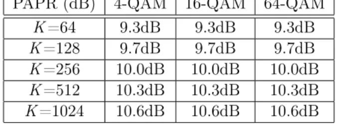
Table 1: PAPR of OFDM comparison for different modulations (atγ = 0.01)
PAPR (dB) 4-QAM 16-QAM 64-QAM
K=64 9.3dB 9.3dB 9.3dB
K=128 9.7dB 9.7dB 9.7dB
K=256 10.0dB 10.0dB 10.0dB
K=512 10.3dB 10.3dB 10.3dB
K=1024 10.6dB 10.6dB 10.6dB
2.2.2 Theoretical estimation of OFDM PAPR
OFDM has high PAPR because of it’s superposition of subacrriers. It is hard to consider about all cases of possible signals. For example, ifK subcarrier OFDM system is assumed with 16-QAM, there
are16K possible cases of data. Fortunately, there are only few of high PAPR signals. Thus, PAPR
is usually expressed by the statistical distribution, complementary cumulative distribution function (CCDF). Physical meaning of CCDF is the probability of the given PAPR value over an given threshold. OFDM symbols are constructed by real and imaginary values with i.i.d. Gaussian random variables. It means the distribution of power of OFDM symbol follows Chi-squared distribution. Then, CCDF of OFDM PAPR can be expressed by
CCDF(γ) =P(PAPR> γ) = 1−(1−e−γ)βK (11)
where K is the number of subcarriers [17]. It is a reasonable trend considering that PAPR of
OFDM is increased by increasing number of subcarriers. Of cause, PAPR is change by modulations, however it is much smaller than influence of changing the number of subcarriers [42]. In Table. 1, PAPR values are represented as different modulations at CCDF (γ = 0.01). It is known that (11)
is not fit on the large K [34]. To solve this problem, β is given as a compensation coefficient for
more accurate prediction. [30]. In the four times oversampled OFDM, β is known as 2.3 [15]. The
detail derivation is explained in Appendix.
2.3 OFDM PAPR Reduction Schemes
2.3.1 Clipping
Clipping is the simplest PAPR reduction scheme. The maximum power of signal |Amax|2is
prede-termined. If the signal is over a limited value of maximum power, the signal value is limited by
|Amax|2 like |x(t)|2= |Amax|2 |x(t)|2 >|Amax|2 |x(t)|2 |x(t)|2 ≤ |A max|2 (12) in the time domain. However, because of changes of the signal, there is possibility to make a
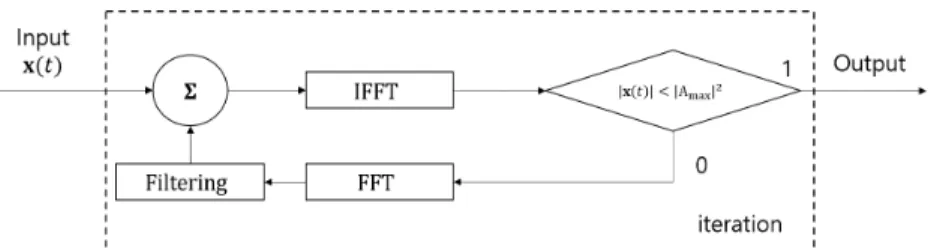
signal distortion. In OFDM, those distorted peaks are related with unexpecatable subcarriers. To solve this problem, iterative clipping and filtering method was proposed in [6]. The main concept is prevent the ICI caused by removing not allowed high peaks using sharp filters to each subcarrier. As the name is represented, the technique repeats clipping and filtering until all overed peaks are removed. In Fig.2, the block diagram of the system is described.
Figure 2: Block diagram of iterative clipping and filtering
2.3.2 Selective mapping and partial transmit sequence
The main concept of SLM or PTS is multiplying phase-shifting set to the part of subcarriers. As shown in the Fig.3, the phase shift can be represented by multiplication between complex exponential values and subcarriers in the OFDM system. Therefore, SLM is easy to adapt phase-shifting sets to each subcarrier [10]. The phase-shifting sets are assumed to be independent to each other. Then, from (11), the PAPR of OFDM SLM is represented by
CCDF(γ) =P(PAPR> γ) = (1−(1−e−γ)βK)U (13)
whereU is the number of independant phase-shifting sets.
Partial transmit sequence is little bit different with SLM. PTS separates subcarriers with smaller set and IFFT those subcarrier sets. These IFFTed subcarriers are multiplied by optimal weighting factors [28]. It is well represented by Fig.4.
Both techniques transmit the information about selected phase-shifting set or weighting factors. It is called side information. A lot of SLM or PTS are not use data subcarriers as side information transmission carrier. However, it is clear that additional resource is needed such as complexity or pilot carriers. The reason why the SLM is focused in this paper is, SLM do not change data rate and OOB.
2.3.3 Tone reservation
Tone reservation(TR) use redundant data symbols to reduce PAPR. Therefore, this method doesn’t need to care about the signal distortion. TR uses predetermined tones as reducing PAPR tones. If the PAPR is not over a threshold, those reserved tones are used for data transmission. In other words, this reservation system losses it’s data rate caused by reserved tone which can’t be used
Figure 3: Block diagram of OFDM SLM
Figure 4: Block diagram of OFDM PTS
for data transmission and PAPR reduction at the same time. To minimize the data loss, about selecting optimal PAPR reduction tone rules or algorithms is researched on [8,20].
2.4 SC-FDMA System Model
SC-FDMA has same advantages as OFDMA. It is suitable for a multiuser system, the high data rate and high spectral efficiency. It is proposed for low-PAPR in uplink system. SC-FDMA is one of precoded OFDMA. Therefore, subcarriers are orthogonal to each other, users need to be synchronized. The total possible subcarriers are devided to each user. If there are N subcarriers,
the number of available subcarriers is Kuser =K/Q, where Qis a number of users. There are two major distributing subcarrier approaches. One is localized FDMA. The LFDMA is almost same as OFDMA except a precoding matrix for each user. Another one is interleaved FDMA. IFDMA has
even-spaced subcarriers with a Q intervals, other users subcarrier are located between them [29].
The examples of two subcarrier distribution are shown in the Fig. 5.
Figure 5: Subcarrier distribution for each user in LFDMA and IFDMA (K=9, Kuser=3) Assuming that among the Qusers, a user makes a transmit uplink signal using SC-FDMA for .
Then the formulation will be
x=FHKPFKuserdKuser (14)
whereP ais permutation matrix which depends on LFDMA or IFDMA,FKuseris aKuser×Kuser
FFT matrix.dKuseris a data symbol vectorKuser by one. The main idea of SC-FDMA is, the FFT
precoding matrix makes signals which have same as symbols at sampling point.
For example, LFDMA has eachdKuservalue in time domain at the each Q sampling point. The
other points have unexpectable complex exponential value.
IFDMA has higher PAPR reduction than LFDMA by using different roll-off factor filters like Fig.6. Even if change roll-off factor 0 to 1, the difference of PAPR of LFDMA is smaller than 1dB. Used number of subcarrier is 64, and used filter is RC filter.
However, IFDMA needs to be strongly synchronized with other users. 7 is show spectrums of LFDMA and IFDMA. In asynchronous environment, it is hard to use IFDMA.
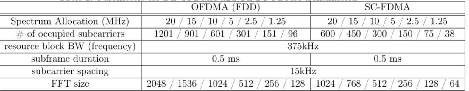
According to [1], considerable OFDMA/SC-FDMA parameters are represented in Table. 3. Table 2: Parameters for DL OFDMA and UL SC-FDMA transmission
OFDMA (FDD) SC-FDMA
Spectrum Allocation (MHz) 20 / 15 / 10 / 5 / 2.5 / 1.25 20 / 15 / 10 / 5 / 2.5 / 1.25
# of occupied subcarriers 1201 / 901 / 601 / 301 / 151 / 96 600 / 450 / 300 / 150 / 75 / 38
resource block BW (frequency) 375kHz
subframe duration 0.5 ms 0.5 ms
subcarrier spacing 15kHz
Figure 6: PAPR of LFDMA and IFDMA
Figure 7: Spectrums of LFDMA and IFDMA
2.5 GFDM
GFDM is proposed by G.Fettweis at 2009 [12]. GFDM, which has K subcarriers, transmits KM
data symbols at once. TheM subsymbols are represented in time domain as amplitidues multiplied
with cirdcular shifted filters. The cyclic shift filter can be denoted byg(t−mT)ej2πfktwherek= 0
toK−1,m= 0 toM−1,T is a time duration of a OFDM symbol. If then, total symbol duration
of GFDM will beMT.fkdoes not have to orthogonal to each other. If data symbol array of GFDM is assumed byd, then thoseKM symbols are multiplied to KM subsymbol carriers by (15).
x(t) = K−1 X k=0 M−1 X m=0 dk,mg(t−mT)ej2πfkt (15)
x[n] = K−1 X k=0 M−1 X m=0 dk,mg(n−mKL)ej2πk n/LK (16)
. Like (4), (16) is noted by a matrix form
x=Ad (17)
whereA is aLKM by KM matrix. According to [13], (17) is same as
x=FHN
K−1 X k=0
P0kΓRFMdk (18)
Ris a repetition matrix with 2M byM,Γis a diagonalized waveform filter which is transformed
to frequency domain and P0kis a mapping and an upsampling matrix. dkis M symbols in k-th
subcarrier. It can be derived by characteristic of DFT. The block diagrams are represented in Fig.8 and Fig.9.
Figure 8: Block diagram of GFDM from [12]
A CP is applicable to the GFDM transmit signal x. As like (8), it is able to represent GFDM
with a CP channel matrix by
y=HcpAd (19)
If a GFDM modulation matrixAhas orthogonally distributed subsymbol carriers in all available
frequency band, Hcp is diagonalized by an FFT matrix. The channel coefficient is matched to the subsymbol carriers. However, in many cases, GFDM is assumed non-orthogonal environments and asynchronized multiusers. There are three major demodulation techniques for GFDM. One is ZF which means multiply anA−1 matrix after removing channel effects. Matched filter is also possible,
but higher interference to adjacent subcarriers, the usually the performance is not enough. The last one is MMSE which has the best performance in those techniques. It is come from higher
Figure 9: Block diagram of GFDM from [13]
computation cost. In [13], proposed iterative cancellation using matched filter, which has a high performance.
GFDM has high degree of freedom in parameter setting. Assuming time duration of an OFDM symbol is T, time duration of GFDM is MT duration. To transmit KM symbols, K subcarrier
OFDM needs M time duration and CP duration. Due to the GFDM transmit KM symbols at
once, GFDM needs only one CP for transmit KM symbols. Therefore, GFDM can have higher
time efficiency than OFDM in some environments. Also it means4f between subsymbol carrier is
closer than OFDM. In same word, longMT rectangular window makes 1/MT zero-crossing sharp
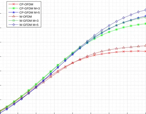
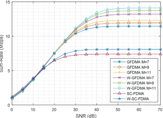
power spectral density for each subsymbol carrier. For this reason, GFDM has a lower OOB than OFDM. If duration of OFDM and GFDM are same, GFDM will have higher data rate. However, it means GFDM loses it’s lower OOB and time efficiency. The lower OOB especially important in asynchronous multiuser environments. In [33], spectral efficiency is shown by Fig. 10, simulated under an asynchronous environment in Rayleigh fading channels. In [45] , sum rate is analyzed comparing between GFDMA and SC-FDMA under asynchronous AWGN channels by Fig. 11. The result clearly shows that GFDM has higher spectral efficiency than OFDM and SC-FDMA.
3
RELATED WORK
3.1 GFDMA
The exact definition of GFDMA is distributing a few sets of subsymbol carriers in same subcarrier to each users. It means, if GFDM is used with some subcarrier sets such as empty other subcarriers for different users, it is satisfies the condition of GFDMA. In [26], a low PAPR GFDMA is proposed comparing with LFDMA and IFDMA. To get the low PAPR, a special parameter setting is used. The number of subsymbol carriers is matched to Kuser of SC-FDMA, number of subcarriers is
SNR (dB)
0 5 10 15 20 25 30 35 40
Spectral Efficiency (bits/s/Hz)
1 2 3 4 5 6 7 8 9 CP-OFDM CP-GFDM M=3 CP-GFDM M=5 W-OFDM W-GFDM M=3 W-GFDM M=5
Figure 10: spectral efficiency of GFDM vs OFDM in the asynchronous system
matched toQ of SC-FDMA. In this paper, GFDMA means the low PAPR GFDMA. Fig.12 shows
that GFDMA has similar PAPR performance with IFDMA and similar OOB with LFDMA. However, if it is assumed that4f of between subsymbol carriers as same as SC-FDMA, GFDMA
loses the advantages of GFDM such as low OOB and time efficiency from CP. Fig.13 shows the spectrum of difference modulations. For fair comparison, assumed same number of subcarriers
K=32, M=5 for GFDM. K=32, Q=4 for OFDMA and SC-FDMA without filter. Because of
parameter set of GFDMA, assumed K=4, M=32. As well shown as Fig.13, GFDMA has a trade
off between loss of OOB and low PAPR performance compare with other techniques.
3.2 Precoded GFDM
In [40], several precoded GFDM techniques are proposed. The basic concpets of main precoded GFDM techniques, such as Block IDFT GFDM(BIDFT GFDM) and DFT precoded GFDM, are start form (16). Those proposed schemes are assumed to use CP. BIDFT GFDM is use characteristic of block diagonalization of (HA)HHA. HAmeans HcpAof the (19). This phenomenon is caused
by IDFT precoding. In [40], the size of IDFT is assumed byN,it called by BIDFT-N GFDM. DFT
precoded GFDM is same concept of the precoding matrix with IFDMA or LFDMA. Therefore, those two method called by LFDMA-GFDM and IFDMA-GFDM. For example, LFDMA-GFDM can be represented by
Figure 11: Sum rate of GFDMA vs SC-FDMA in the asynchronous system
xLF DM A−GF DM =APKM(FNDF T ⊗IKM/NDF T)d (20)
where ⊗ means Kronecker product, PKM is a permutation matrix. In LFDMA-GFDM, PKM is an identity matrix. The block diagram of DFT precoded GFDM is represented in Fig.14.
Linear precoding with iterative algorithm GFDMA also proposed by [38]. It is improved version of BIDFT GFDM iteratively using a precoding matrix to data symbols.
Clipping is also available for GFDM. [35] proposed a concept with iterative receiver for a clipped GFDM signal. Basically, a block diagram of clipped GFDM is same as Fig.2 without that GFDM modulation and demodulation are used in the processing. In the Fig. 2 of [35] shows around 4 dB PAPR at CCDF(0.1%). However, it is clear that the clipping method has disadvantages on the exact signal transmission, it is shown as lower performance of bit error rate. The self-interference of GFDM makes negative synergy with clipping. Thus, the clipping method doesn’t be considered in this paper.
Figure 12: PAPR of SC-FDMA and GFDMA
4
CONCEPT OF GFDM SLM
Compare with OFDM, GFDM has more superpositions of M subsymbol carriers. If OFDM and
GFDM are assumed to use same number of subcarriers, as mentioned in Section 2.2.1, PAPR of GFDM is higher than OFDM. The basic structure of GFDM is similar with OFDM. It means tra-ditional OFDM PAPR reduction, introduced in Section 2.3, would be adaptable to GFDM system. In this paper, SLM is considered for GFDM PAPR reduction among several OFDM PAPR reduc-tion techniques. An SLM technique doesn’t make changes of basic data symbols and waveform of subsymbol carriers on GFDM. Also, there are no clipping distortions and rate losses by redundant symbols like TR.
The simplest way to apply the GFDM SLM is to apply KM phase-shifting arrays to the matched subsymbol carriers. However, since the GFDM modulation is performed on the time axis, it is not easy to directly apply SLM in frequency domain like OFDM SLM. Therefore, the block diagram of GFDM SLM can be represented by Fig.15 [31].
The important note is, GFDM SLM should be avoided to overlapping subsymbol waveforms which have same subcarrier index. For this problem, the simple overlapping avoidance algorithm is applied in the simulation. The random phase-shifting set has too much possible cases, and it is not realistic applicable. As same as OFDM SLM limits it’s specific phase-shifting set, the simplified phase-shifting set is proposed [41].
Assumed phase-shifting set {± 1, ± i} has two major advantages. First, the structure is able to simplified. As phase-shifting set has determined inverse or not. The phase shift can be possible to multiply to the data symbols before GFDM modulation. Therefore, Fig.15 is replaced to Fig.16. [31] Another advantage is it does not need to add the overlapping avoidance algorithm. The proposed
Figure 13: The spectrum of OFDMA, SC-FDMA, GFDM, and GFDMA
Figure 14: Block diagram of DFT precoded GFDM
phase-shifting set doesn’t affect to circular shift of subsymbol carrier waveform. Therefore, the subsymbol carriers are never overlap to each other. It can be also available for low-complexity GFDM [13].
In GFDM, subsymbol carriers with the same frequency can be assumed to be subcarriers multi-plied by a cyclic shift filter and a data symbol on the time domain. Therefore, (11) can be expressed by
CCDF(γ) =P(PAPR> γ) = (1−(1−e−γ)αKM)U (21)
where compensation coefficient α is different withβ of OFDM, U is the number of independant
phase-shifting set.
Determines the OOB because it is the period MT of the GFDM signal, since it does not affect the period or the frequency band of the signal. The received signal is distinguished at the receiving end by a square filter, where the sinc spectrum is multiplied by the square frequency filter for each frequency component. In OFDM, the interference between data symbols is 0 due to orthogonality,
Figure 15: Block diagram of basic GFDM SLM
Figure 16: Block diagram of simplified GFDM SLM
but in the asynchronous situation, interference is greatly increased by adjacent OFDM signals. On the other hand, since the GFDM signal having a long period has a lower OOB as the period of the square filter increases, the influence of interference is less than that of OFDM in an asynchronous situation. Even if SLM is applied, OOB is not changed for same parameters.
5
PERFORMANCE ANALYSIS
5.1 Performance Evaluation of PAPR
Consider about Table. 2, the parameter setting of PAPR for OFDM SLM, GFDM SLM and SC-FDMA are defined as Table. 3. U = 0 means the original signal without SLM.
Fig.17 is shown difference between simulation results and theoretical estimations. From [15], PAPR of OFDM SLM is well fit on (11) withβ= 2.3and K= 128. For the(21),α is approximately
2.8 from simulation for given conditions. The average error of GFDM SLM is 0.1dB. In same sense, Fig. (18) plots the simulations and estimations for different parameters. As same as OFDM SLM,α
is changed by as changing the parameters in GFDM SLM. This result means that the estimation is closely matched to simulations. With feasible coefficients, the estimation is possible to replace the
Table 3: OFDM SLM, GFDM SLM and SC-FDMA system parameters Parameters Value Subcarrier spacing,4fk 15KHz Number of subcarrier, K 16, 64, 128, 256 Number of subsymbols, M 5 Number of oversampling,L 4 Number of trial 50000
Number of phase-shifting set,U 0 (w/o SLM), 2, 4, 8, 16, 32, 64, 128
phase-shifting set {±1,±i}
Filter Raised cosine (roll off factor, a = 0.1, 0.5, 0.9)
Number of users, Q 4
Block size of BIDFT-N 64
DFT precoding size,NDF T 4
Data symbol modulation 16-QAM
simulations for significant parameters.
Figure 17: PAPR of simulations and theoretical estimations. (a) OFDM SLM K = 128, β = 2.3,
(b) GFDM SLM K= 128, M = 5, α= 2.8and a = 0.5
Fig.19 represents PAPR of GFDM SLM and other PAPR reduction techniques. The parameters areK = 64,M = 5 andQ = 4 for OFDMA, GFDMA and SC-FDMA. GFDM SLM makes significant
PAPR reduction compare with original GFDM. Maximum PAPR reduction is 3.8dB, the PAPR difference with OFDM SLM is around 1dB. Reducing the lowest PAPR is hard to achievable. Because of large number of subsymbol carriers, the minimum PAPR of GFDM SLM is larger than SC-FDMA around 2.5dB. At CCDF(0.1%), U=8 or above condition is required to approach to the
LFDMA PAPR. U=4 is enough for higher PAPR performance than OFDMA system.
The PAPR of precoded matrices have higher PAPR than GFDMA. Because, the parameters are same as GFDM SLM, there are physical limitation to reduce PAPR. The main key of reducing PAPR
Figure 18: PAPR of simulations and theoretical estimations with different parameters is IDFT spreading. If assume GFDM has KM sampling points in time domain, each mK sample
point has same amplitude with data symbols. Without filter, interleaved M GFDM subsymbols
become same as IFDMA modulation. In time domain, those M subsymbols are repeated and it’s
amplitude is spreaded by √1
K. Therefore, BIDFT-N has lower PAPR than general GFDM. However IFDMA-GFDM and LFDMA-GFDM used a partial FFT matrix. Even if used a permutation matrix, it doesn’t make large changes. Because of DFT spreading effect, the PAPR is slightly reduced than original GFDM. Compare with GFDM SLM, U=2 is enough to get same performance with DFT
precoded GFDM and U=4 or 8 is enough to get better PAPR performance than BIDFT-N GFDM at CCDF(0.1%).
5.2 Spectrum Analysis
The introduced GFDM PAPR reduction techniques have a common similarity. Data symbol array of GFDM,dis consisted by i.i.d. QAM. The expectation of each symbol power is 1 and the PSD will
not changed by DFT or IDFT precoding. It means the precoded GFDM has a same spectrum with GFDM when the common parameters are same. In the GFDM SLM case, the power of a phase
Figure 19: PAPR comparison of GFDM SLM, GFDMA and SC-FDMA.
shift is 1. Therefore, the spectrum of GFDM SLM is same as GFDM. GFDMA is assumed the specific parameters for the lowest PAPR GFDMA, the spectrum of GFDMA is higher than general GFDM and LFDMA. It is shown in the Fig. 21. Table. 4 shows detail interference to adjacent user considering some guard subcarrier by different modulations from Fig. 21.
Table 4: Interference to adjacent user as guard subcarriers
K = 64,M = 5,Q = 4 0 guard subcarrier 1 guard subcarrier 3 guard subcarrier
OFDMA, LFDMA -10 dB -14 dB -16 dB
GFDM, GFDM SLM, precoded GFDM -17 dB -20 dB -23 dB
GFDMA -7 dB -8.5 dB -10 dB
5.3 Spectral Efficiency
Spectral efficiency is one of useful tool for performance analysis which is unit of(bit/s)/Hz.
Some-times spectral efficiency called by sum rate. According to parameters from 5, the spectral efficiency is simulated for noted PAPR reduction techniques. In this simulation,only Rayleigh fading is as-sumed, not AWGN channel. One of important notice for the simulation setting is GFDM and GFDMA is devided by 24fk. In fact, GFDM use less than 24fk BW. Due to the frequency do-main RC filter, around edge subsymbol carriers have zero values. Which means, effective BW of GFDM is smaller than 2M. Especially in GFDMA, it use 24 subsymbol carriers with 4fM. The difference between subsymbol carriers are increased to4f , GFDMA has much spreaded frequency
Figure 20: PAPR comparison of GFDM SLM and precoded GFDM.
domain RC filter than original GFDM. From Shannon’s theoremC=B∗log2(1 +PPNs), the spectral
efficiency,S is represented by
S =log2(1 + Ps PN
)/B (22)
whereB is BW,Ps andPN are average signal power and average interference power. The effect of channel removed by ZF channel equalizer, it enhance the noise power if the channel is an ill-conditioned matrix. Considering noise enhancement and effective BW of all method, the simulation result of spectral efficiency is able to represent by the Fig. 22. GFDM SLM has better performance than precoded GFDM or GFDMA with 5.
6
CONCLUSION AND FUTURE WORK
In this paper, the GFDM SLM is proposed for reducing PAPR of GFDM without signal distortions. From a traditional OFDM SLM technique, the limited phase-shifting set is applied for a simplify-ing structure. Also the PAPR estimation equation is compared with simulation for approximated compensated coefficients by different parameters. For comparing performance, other PAPR reduc-tion schemes are considered such as SC-FDMA, low PAPR GFDMA and precoded GFDM. GFDM SLM technique can be achieved a significant PAPR reduction compare with original GFDM, as increasing number of phase-shifting sets. Compare with other GFDM PAPR reduction techniques, the proposed GFDM SLM technique has lower PAPR than precoded GFDM by a few number of phase-shifting set. Due to the same spectrum characteristics with GFDM, GFDM SLM has low
Figure 21: Spectrum of PAPR reduction techniques.
Table 5: Parameters for spectral efficiency of PAPR reduction techniques in ZF-receiver
Parameters Value
Number of trial 100000
Subcarrier spacing,4fk 15KHz
Number of effective subcarriers,K 12
Number of subsymbols, M 5
Filter and roll off factor Raised cosine, 0.5
Number of users,Q 4
Number of oversampling,L 4
Block size of BIDFT-N K
DFT precoding size,NDF T 4
Data symbol modulation 16-QAM
Rayleigh fading with 6 taps
OOB and enough spectral efficiency. The cases of SC-FDMA and low PAPR GFDMA have the lowest boundary of PAPR. However SC-FDMA is not suitable for asynchronous environments as shown as Fig. 10 and Fig. 11. As shown as Fig. 21 and Fig. 22, GFDMA have loss in OOB and spectral efficiency.
The proposed SLM technique is focused on PAPR and efficiency. Even if the complexity is re-duced by limited phase-shifting set, it has higher complexity than precoded GFDM or SC-FDMA. In OFDM SLM, there are some trials to pick optimal phase-shifting set for low complexity and optimal PAPR. Those schemes are one of considerable way to develop proposed idea. Another developable topic is the side information. SLM technique use side information for transmit information about used phase-shifting set. Even if the side information is assumed that excluded in the data symbols, it makes loss in other transmission processing. This is the second challangable problem as a future works.
Figure 22: Spectral efficiency of PAPR reduction methods
APPENDIX. A
From (3),x[n]is consisted by uncorrelated in-phase and quadrature-phase like
x[n] =xI[n] +xQ[n] (23) for0≤n≤N−1in . dis array of OFDM symbols that has QAM constellation. Every elements
of d is i.i.d.. For large N, by the central limit theorem, it will follows Gaussian distribution with
CN ∼(0,σ22). The probability density function of amplitude is noted by
p(xI) =p(xQ) = 1 √ 2πσ2e −x2 2σ2 (24)
which same as Rayleigh distribution. PAPR is equal to (10), |x[n]|2 = (x
I[n])2+ (xQ[n])2, the power of|x[n]|2 has Chi-square distribution,
P(|x[n]|2 =γ) = 2γ e−γ2 (25)
From probability density function, CDF can be noted by 1−e−γ. Because, DFT of i.i.d. is also i.i.d, time domain value x[n] are i.i.d. For the N symbols, the cumulative density function is
CCDF(P AP R > γ) = 1−(1−e−γ)N (26)
APPENDIX. B
In LFDMA, let’s assumedkisk-th complex data symbol,dk0 is DFT ofdk of userQ.
Xq is a frequency domain data array of user q where (0≤ q ≤ Q−1) for total subcarrier K, K=KuserQ. Then Xq is same as Xq[l] = d0l l=k+ qKQ (0≤k≤Kuser−1) 0 otherwise (27) The Tx signalxq is noted by
xq[r] = 1 K K−1 X l=0 Xq[l]e j2π l r K = 1 K Kuser−1 X l=0 Xq[l]e j2π l r K (28)
At the Qk points in time domain,
xq[Qk] = 1 K K Q K−1 X l=0 Xq[l]e j2π k r K/Q ! = 1 Q[d0, d1,· · ·, dKuser−1] (29) Therefore xq = 1 Q[d0,∗,∗ · · ·d1,∗,∗ · · ·, dKuser−1,∗,∗,· · ·] (30)
In IFDMA, Then Xq is same as
Xq[l] = d0l l=Qk+q(0≤k≤Kuser−1) 0 otherwise (31) The Tx signalxq is noted by
xq[r] = 1 K K−1 X l=0 Xq[l]e j2π l r K (32)
xq[r] = 1 K K Q K−1 X l=0 Xq[l]e j2π k r Kuser ! = 1 Q[d0, d1,· · ·, dKuser−1] (33) r =Kuser, then e j2π k Kuser Kuser = 1.
Therefore,xq[Kuser] = dQ0 is repeated.
∴xq =
1
References
[1] 3GPP. "Physical layer aspect for evolved Universal Terrestrial Radio Access (UTRA)". TR 25.814, 3rd Generation Partnership Project (3GPP), October 2006.
[2] 3GPP. Evolved Universal Terrestrial Radio Access (E-UTRA); Physical channels and modula-tion. TS 36.211, 3rd Generation Partnership Project (3GPP), September 2008.
[3] 3GPP. "Radio subsystem synchronization". TS 45.010, 3rd Generation Partnership Project (3GPP), September 2008.
[4] S. Ben Aissa, M. Hizem, and R. Bouallegue. "asynchronous ofdm interference analysis in multi-user cognitive radio networks". In 2016 International Wireless Communications and Mobile Computing Conference (IWCMC), pages 1135–1140, Sept 2016.
[5] J. G. Andrews, S. Buzzi, W. Choi, S. V. Hanly, A. Lozano, A. C. K. Soong, and J. C. Zhang. "what will 5g be?". IEEE J. Sel. Areas Commun., 32(6):1065–1082, June 2014.
[6] J. Armstrong. "peak-to-average power reduction for ofdm by repeated clipping and frequency domain filtering". Electronics letters, 38(5):1, 2002.
[7] S. A. Cheema, K. Naskovska, M. Attar, B. Zafar, and M. Haardt. "performance comparison of space time block codes for different 5g air interface proposals". InWSA 2016; 20th International ITG Workshop on Smart Antennas, pages 1–7, March 2016.
[8] J. C. Chen and C. P. Li. "tone reservation using near-optimal peak reduction tone set selection algorithm for papr reduction in ofdm systems". IEEE Signal Process. Lett., 17(11):933–936,
2010.
[9] L. Cimini. "analysis and simulation of a digital mobile channel using orthogonal frequency division multiplexing". IEEE Trans. Commun., 33(7):665–675, 1985.
[10] L. J. Cimini and N. R. Sollenberger. "peak-to-average power ratio reduction of an ofdm signal using partial transmit sequences". IEEE Commun. Lett., 4(3):86–88, 2000.
[11] M. Debbah. "short introduction to ofdm". White Paper, Mobile Communications Group, Institut Eurecom, 2004.
[12] G. Fettweis, M. Krondorf, and S. Bittner. "gfdm - generalized frequency division multiplexing". In VTC Spring 2009 - IEEE 69th Vehicular Technology Conference, pages 1–4, April 2009.
[13] I. Gaspar, N. Michailow, A. Navarro, E. Ohlmer, S. Krone, and G. Fettweis. "low complexity gfdm receiver based on sparse frequency domain processing". In Vehicular Technology Confer-ence (VTC Spring), 2013 IEEE 77th, pages 1–6. IEEE, 2013.
[14] A. Ghosh and R. Chen D.R. Wolter, J.G. Andrews. "broadband wireless access with wimax/802.16: current performance benchmarks and future potential". IEEE Commun. Mag.,
43(2):129–136, 2005.
[15] S. H. Han and J. H. Lee. "modified selected mapping technique for papr reduction of coded ofdm signal". IEEE Trans. Broadcast., 50(3):335–341, 2004.
[16] J. Heiskala and J. Terry. "OFDM wireless LANs: A theoretical and practical guide". Sams,
2001.
[17] T. Jiang and Y. Wu. "an overview: peak-to-average power ratio reduction techniques for ofdm signals". IEEE Trans. Broadcast., 54(2):257, 2008.
[18] V. Kotzsch and G. Fettweis. "interference analysis in time and frequency asynchronous network mimo ofdm systems". In 2010 IEEE Wireless Communication and Networking Conference,
pages 1–6, April 2010.
[19] B. S. Krongold and D. L. Jones. "an active-set approach for ofdm par reduction via tone reservation". IEEE Trans. Signal Process., 52(2):495–509, Feb 2004.
[20] B. S. Krongold and D. L. Jones. "an active-set approach for ofdm par reduction via tone reservation". IEEE Trans. Signal Process., 52(2):495–509, 2004.
[21] G. Li and G. L. Stube. "Orthogonal frequency division multiplexing for wireless communica-tions". Springer Science & Business Media, 2006.
[22] X. Li and L. J. Cimini. Effects of clipping and filtering on the performance of ofdm. IEEE Commun. Lett., 2(5):131–133, May 1998.
[23] X. Li, F. Ng, and T. Han. "carrier frequency offset mitigation in asynchronous cooperative ofdm transmissions". IEEE Trans. Signal Process., 56(2):675–685, Feb 2008.
[24] M. MatthÃľ, L. L. Mendes, and G. Fettweis. "asynchronous multi-user uplink transmission with generalized frequency division multiplexing". In 2015 IEEE International Conference on Communication Workshop (ICCW), pages 2269–2275, June 2015.
[25] Y. Medjahdi, M. Terre, D. L. Ruyet, D. Roviras, and A. Dziri. "performance analysis in the downlink of asynchronous ofdm/fbmc based multi-cellular networks". IEEE Trans. Wireless Commun., 10(8):2630–2639, August 2011.
[26] N. Michailow and G. Fettweis. "low peak-to-average power ratio for next generation cellular systems with generalized frequency division multiplexing". In 2013 International Symposium on Intelligent Signal Processing and Communication Systems, pages 651–655, Nov 2013.
[27] N. Michailow, M. MatthÃľ, I. S. Gaspar, A. N. Caldevilla, L. L. Mendes, A. Festag, and G. Fettweis. "generalized frequency division multiplexing for 5th generation cellular networks".
IEEE Trans. Commun., 62(9):3045–3061, Sept 2014.
[28] S. H. Muller and J. B. Huber. "ofdm with reduced peak-to-average power ratio by optimum combination of partial transmit sequences". Electronics Letters, 33(5):368–369, Feb 1997.
[29] H. G. Myung, J. Lim, and D. J. Goodman. "single carrier fdma for uplink wireless transmis-sion". IEEE Veh. Technol. Mag., 1(3):30–38, 2006.
[30] H. Ochiai and H. Imai. "on the distribution of the peak-to-average power ratio in ofdm signals".
IEEE Trans. Commun., 49(2):282–289, 2001.
[31] H. Oh and H. J. Yang. "PAPR Reduction Scheme Using Selective Mapping in GFDM".J-KICS,
41:698–706, 2016.
[32] A. Osseiran, F. Boccardi, V. Braun, K. Kusume, P. Marsch, M. Maternia, O. Queseth, M. Schellmann, H. Schotten, H. Taoka, H. Tullberg, M. A. Uusitalo, B. Timus, and M. Fallgren. "scenarios for 5g mobile and wireless communications: the vision of the metis project". IEEE Commun. Mag., 52(5):26–35, May 2014.
[33] W. J. Park and H. J. Yang. "on spectral efficiency of asynchronous gfdma and sc-fdma in frequency selective channels". In 2016 IEEE 83rd Vehicular Technology Conference (VTC Spring), pages 1–5, May 2016.
[34] J. Orriss S. Shepherd and S. Barton. "asymptotic limits in peak envelope power reduction by redundant coding in orthogonal frequency-division multiplex modulation". IEEE Trans. Commun., 46(1):5–10, 1998.
[35] L. Sendrei, S. Marchevsk`y, N. Michailow, and G. Fettweis. " iterative receiver for clipped gfdm signals". In Radioelektronika (RADIOELEKTRONIKA), 2014 24th International Conference,
pages 1–4. IEEE, 2014.
[36] K. Seong, M. Mohseni, and J. M. Cioffi. "optimal resource allocation for ofdma downlink systems". In 2006 IEEE International Symposium on Information Theory, pages 1394–1398,
July 2006.
[37] S. Sesia, I. Toufik, and M. Baker. "LTE-the UMTS long term evolution". Wiley Online Library,
2015.
[38] Z. Sharifian, M. J. Omidi, H. Saeedi-Sourck, and A. Farhang. "linear precoding for papr reduction of gfdma". IEEE Wireless Commun. Lett., 5(5):520–523, 2016.
[39] T. Nakamura. "Proposal for Candidate Radio Interface Technologies for IMT-Advanced Based on LTE Release 10 and Beyond Takehiro Nakamura". ITU-R WP 5D 3rd Workshop on IMT-Advanced, (,):50–52, 2009.
[40] S. Tiwari, SS. Das, KK. Bandyopadhyay, and K. Kalyan. "precoded generalised frequency division multiplexing system to combat inter-carrier interference: performance analysis". [41] C. L. Wang and S. J. Ku. "novel conversion matrices for simplifying the ifft computation of an
slm-based papr reduction scheme for ofdm systems". IEEE Trans. Commun., 57(7):1903–1907,
2009.
[42] X. Wang, T. T. Tjhung, and C. S. Ng. "reduction of peak-to-average power ratio of ofdm system using a companding technique". IEEE Trans. Broadcast., 45(3):303–307, 1999.
[43] G. Wunder, P. Jung, M. Kasparick, T. Wild, F. Schaich, Y. Chen, S. T. Brink, I. Gaspar, N. Michailow, A. Festag, L. Mendes, N. Cassiau, D. Ktenas, M. Dryjanski, S. Pietrzyk, B. Eged, P. Vago, and F. Wiedmann. "5gnow: non-orthogonal, asynchronous waveforms for future mobile applications". IEEE Commun. Mag., 52(2):97–105, February 2014.
[44] G. Wunder, M. Kasparick, S. ten Brink, F. Schaich, T. Wild, I. Gaspar, E. Ohlmer, S. Krone, N. Michailow, A. Navarro, G. Fettweis, D. Ktenas, V. Berg, M. Dryjanski, S. Pietrzyk, and B. Eged. "5gnow: Challenging the lte design paradigms of orthogonality and synchronicity". In 2013 IEEE 77th Vehicular Technology Conference (VTC Spring), pages 1–5, June 2013.
[45] W. J. Park H. J. Yang and H. Oh. "sum rates of asynchronous gfdma and sc-fdma for 5g uplink". ICT Express, 1(3):127–131, 2015.
[46] X. Zhang, M. Jia, L. Chen, J. Ma, and J. Qiu. "filtered-ofdm - enabler for flexible waveform in the 5th generation cellular networks". In 2015 IEEE Global Communications Conference (GLOBECOM), pages 1–6, Dec 2015.


![Figure 8: Block diagram of GFDM from [12]](https://thumb-us.123doks.com/thumbv2/123dok_us/11106627.2998335/22.918.219.702.504.744/figure-block-diagram-of-gfdm-from.webp)
![Figure 9: Block diagram of GFDM from [13]](https://thumb-us.123doks.com/thumbv2/123dok_us/11106627.2998335/23.918.250.703.128.395/figure-block-diagram-of-gfdm-from.webp)