Rochester Institute of Technology Rochester Institute of Technology
RIT Scholar Works
RIT Scholar Works
Theses
8-2020
Leveraging Programmable Data Plane For Compressing
Leveraging Programmable Data Plane For Compressing
Forwarding Tables
Forwarding Tables
Garegin GrigoryanFollow this and additional works at: https://scholarworks.rit.edu/theses Recommended Citation
Recommended Citation
Grigoryan, Garegin, "Leveraging Programmable Data Plane For Compressing Forwarding Tables" (2020). Thesis. Rochester Institute of Technology. Accessed from
This Dissertation is brought to you for free and open access by RIT Scholar Works. It has been accepted for inclusion in Theses by an authorized administrator of RIT Scholar Works. For more information, please contact [email protected].
by
Garegin Grigoryan
A dissertation submitted in partial fulfillment of the requirements for the degree of
Doctor of Philosophy
in Computing and Information Sciences
B. Thomas Golisano College of Computing and Information Sciences
Rochester Institute of Technology Rochester, New York
Leveraging Programmable Data Plane For Compressing Forwarding Tables
by
Garegin Grigoryan
Committee Approval:
We, the undersigned committee members, certify that we have advised and/or supervised the candidate on the work described in this dissertation. We further certify that we have reviewed the dissertation manuscript and approve it in partial fulfillment of the requirements of the degree of Doctor of Philosophy in Computing and Information Sciences.
Dr. Minseok Kwon Date
Dissertation Advisor
Dr. M. Mustafa Rafique Date
Dissertation Committee Member
Dr. H.B. Acharya Date
Dissertation Committee Member
Dr. Yaoqing Liu Date
Dissertation Committee Member
Dr. Jayanti Venkataraman Date
Dissertation Defense Chairperson
Certified by:
Dr. Pengcheng Shi Date
Ph.D. Program Director, Computing and Information Sciences
c
2020 Garegin Grigoryan All rights reserved.
Leveraging Programmable Data Plane For Compressing Forwarding Tables
by
Garegin Grigoryan Submitted to the
B. Thomas Golisano College of Computing and Information Sciences Ph.D. Program in Computing and Information Sciences
in partial fulfillment of the requirements for the
Doctor of Philosophy Degree
at the Rochester Institute of Technology
Abstract
The Forwarding Information Base (FIB) resides in the data plane of a routing device and is used to forward packets to a next-hop, based on packets’ destination IP addresses. The constant growth of a FIB forces net-work operators to spend more resources on maintaining memory with line-rate Longest Prefix Match (LPM) lookup in a FIB, namely, expensive and energy-hungry Ternary Content-Addressable Memory (TCAM) chips. In this work, we review two different approaches used to mitigate the FIB overflow problem. First, we investigate FIB aggregation, i.e., merging adjacent or overlapping routes with the same next-hop while preserving the forwarding behavior of a FIB. We propose a near-optimal algorithm, FIB Aggregation with Quick Selections (FAQS), that minimizes the FIB churn and speeds BGP update processing by more than twice. In the meantime, FAQS preserves a high compression ratio (at most 73%). FAQS handles BGP up-dates incrementally, without the need of re-aggregating the entire FIB table. Second, we investigate FIB (or route) caching, when TCAM holds only a portion of a FIB that carries most of the traffic. We leverage the emerging concept of the programmable data plane to propose a Programmable FIB Caching Architecture (PFCA), that allows cache-victim selection at the line rate and significantly reduces the FIB churn compared to FIB aggregation. PFCA achieves 99.8% cache-hit ratio with only 3.3% of the FIB placed in a FIB cache. Finally, we extend PFCA’s design with a novel approach of integrating incremental FIB aggregation and FIB caching. Such integration needed to overcome cache hiding challenge when a less specific prefix in a cache hides a more specific prefix in a secondary FIB table, which leads to incorrect LPM matching at the cache. In Combined FIB Caching and Aggregation (CFCA), cache-hit ratio is maximized up to 99.94% with only 2.5% entries of the FIB, while the total number of route changes in TCAM is reduced by more than 40% compared to low-churn FIB aggregation techniques.
Research
I am very grateful to my first advisor, Dr. Yaoqing Liu for his constant help and motivation. Most of the research work presented in this document, such as FIB Aggregation with Quick Selections (FAQS) and the Programmable FIB caching Architecture (PFCA) was done under Dr. Liu’s direct support and guidance. I hope to continue my collaboration with Dr. Liu as I consider it essential for my future research achievements.
I was very lucky to continue my Ph.D studies at Rochester Institute of Technology. My sincere gratitude goes to my advisor Dr. Minseok Kwon for supporting and guiding through new areas of research as well as helping me to restart my professional career. Specifically, I would like to thank Dr. Kwon for his insightful comments on writing a research paper and doing a research presentation.
General
It has been an exciting journey, that started at the Clarkson University of the North Country. My gratitude goes to the Computer Science faculty of Clarkson University, particularly, Dr. Christopher Lynch, Dr. Alexis Maciel, Dr. Christino Tamon, Dr. Jeanna Matthews.
At RIT, I had a great opportunity to learn from and work with wonderful faculty and staff - that includes Dr. Mohan Kumar, Dr. Pengcheng Shi, Dr. M. Mustafa Rafique, Dr. H. B. Acharya, Dr. Leon Reznik, Dr. Peizhao Hu, Lorrie Jo Turner, Min-Hong Fu, Amanda Zeluff.
I am extremely grateful to my parents for supporting me from the very first day.
Thank you Alan Beadle for the support and motivation.
Thank you Ashok Babel for being a great and reliable friend.
Thanks to John Marshall and James Coole for supporting me during my Cisco internship. Special thanks go to my friends and colleagues: Alain Lafaye, Behman Mofakham, Suman Bhowmick, Soham Dongar-gaonkar, Igor Khokhlov, Sahil Gupta, Nibesh Shrestha, Avinash Maurya, Andrei Aleksandrov, Eleanor Kellam, Matthiew Turner, Patrick Jaouen, Jeffrey D. Carr, Susan Gemmett, Mathieu Wong, Keivan Bah-mani, Steve Liebich, Paul D. Holt, Austin Jantzi, Rasool Mazruee, Masoud Moghaddam, Hamid Eisazadeh, William van Doorn.
To my parents, Hasmik and Alexandr Grigoryan, and my brother, Artashes Grigoryan.
This thesis is based on the following conference papers and journal articles:
1. Grigoryan, G., Liu, Y., Kwon, M. 2020. PFCA: a programmable FIB caching architecture. To appear in IEEE/ACM Transactions on Networking (ToN).
2. Grigoryan, G., Liu, Y., Kwon, M., 2020. Boosting FIB Caching Performance with Aggregation. In Proceedings of the 29th International Symposium on High-Performance Parallel and Distributed Computing. 2020, ACM [31].
3. Liu, Y., Grigoryan, G., 2018, November. Toward incremental FIB aggregation with quick selections (FAQS). In Proceedings of 17th International Symposium on Network Computing and Applications (NCA) (pp. 1-8). 2018, IEEE [46];
4. Grigoryan, G., Liu, Y., 2018. PFCA: a programmable FIB caching architecture. In Proceedings of the 2018 Symposium on Architectures for Networking and Communications Systems (pp. 97-103). 2018, ACM [30].
5. Grigoryan G., Liu Y. ”Toward a programmable FIB caching architecture,” In Proceedings of IEEE 25th International Conference on Network Protocols (ICNP), Toronto, ON, 2017, pp. 1-2 [29].
The co-authors of the listed papers gave their permission to use the papers for this document.
Abbreviations
AS Autonomous System
BT Binary Tree
CFCA Combined FIB Caching and Aggregation DRAM Dynamic Random Access Memory FAQS FIB Aggregation with Quick Selections FIB Forwarding Information Base
ISP Internet Service Provider LPM Longest Prefix Match
LTHD Light Traffic Hitters Detection module PFCA A Programmable FIB Caching Architecture PSA Portable Switch Architecture
PT Patricia Tree
RIB Routing Information Base
RM Route Manager
SRAM Static Random Access Memory TCAM Ternary Content-Addressable Memory
1 Introduction 1 1.1 Problem overview . . . 1 1.2 FIB aggregation . . . 3 1.3 FIB caching . . . 3 1.4 Our contribution . . . 4 1.5 Organization . . . 6 2 Background 7 2.1 Routing basics . . . 7
2.2 Longest Prefix Match (LPM) rule . . . 8
2.3 LPM at the data plane . . . 9
3 FIB Aggregation with Quick Selections 11 3.1 Introduction . . . 11
3.2 Data structures . . . 12
3.3 Design . . . 14
3.3.1 Static FIB aggregation . . . 14
CONTENTS x
3.3.2 Incremental FIB update handling . . . 17
3.4 Evaluation of FAQS . . . 20
3.4.1 Verifying the Forwarding Equivalence with VeriTable . . . 21
3.4.2 IPv4 results . . . 23
3.4.3 IPv6 results . . . 26
3.5 FAQS. Conclusion . . . 27
4 A Programmable FIB Caching Architecture 28 4.1 Introduction . . . 28
4.2 Programmable data plane . . . 30
4.3 Design . . . 31
4.3.1 Overview . . . 31
4.3.2 Route manager . . . 33
4.3.3 Light Traffic Hitters Detection . . . 40
4.4 P4 prototype . . . 42
4.5 Complexity . . . 43
4.6 Evaluation of PFCA . . . 44
4.6.1 Experiment setup . . . 44
4.6.2 Tuning the FIB caching architecture . . . 44
4.6.3 Results . . . 45
4.7 PFCA. Discussion . . . 48
5 CFCA: Combined FIB Caching and Aggregation 50
5.1 Introduction . . . 50
5.2 Design of CFCA . . . 51
5.2.1 Control plane workflow . . . 52
5.2.2 Data plane workflow . . . 60
5.2.3 Complexity of CFCA’s aggregation . . . 61
5.3 CFCA. Evaluation . . . 61
5.3.1 Experimental setup . . . 62
5.3.2 CFCA vs FIB Caching (PFCA) . . . 63
5.3.3 CFCA vs FIB Aggregation (FAQS/FIFA-S) . . . 66
5.3.4 Evaluating a heavier trace . . . 66
5.4 CFCA. Conclusion . . . 67 6 Related Work 68 6.1 FIB aggregation . . . 68 6.2 FIB caching . . . 69 7 Conclusion 72 7.1 Discussion . . . 72 7.2 Limitations . . . 73 7.3 Future work . . . 73 Appendices 82
CONTENTS xii
A Algorithms of FAQS 83
B Algorithms of PFCA 87
C Listings for Light Traffic Hitters Detection Module 88
D Algorithms of CFCA 91
1.1 BGP table growth. . . 2
2.1 The architecture of a traditional router running BGP protocol. . . 8
2.2 Longest Prefix Matching in TCAM. . . 9
3.1 PT and BT for FIB entries from Table 3.1a. . . 13
3.2 Static FIB aggregation of FIB from Table 3.1a. . . 15
3.3 Incremental FIB update handling by FAQS. . . 19
3.4 Prefix withdrawal handling by FAQS. . . 19
3.5 VeriTable algorithm. . . 22
3.6 AS neighbor statistics. . . 23
3.7 FIB aggregation of IPv4 routing table (AS 3356). . . 25
3.8 FIB aggregation of IPv4 routing table (AS 3130). . . 25
3.9 FIB ratio, IPv4 FIB tables. . . 26
3.10 FIB aggregation of IPv6 routing table (AS 6939). . . 27
4.1 Cache hiding example. . . 29
LIST OF FIGURES xiv
4.2 Portable Switch Architecture (PSA). . . 30
4.3 FIB caching architecture. . . 32
4.4 Prefix extension in PFCA. . . 35
4.5 BGP updates processing by RM. . . 37
4.6 Data plane workflow . . . 39
4.7 Light Traffic Hitters Detection. Example. . . 40
4.8 Cache-miss ratio with popularity-based victim selection. . . 46
4.9 Cache-miss ratio with random victim selection . . . 46
4.10 Cache-miss ratio with heap-based victim selection. . . 46
4.11 Size of Level-1, Level-2 caches and the full FIB. . . 46
4.12 Installations and evictions in the full Level-1 cache. . . 46
4.13 Number of BGP updates in the Level-1, Level-2 caches and the full FIB. . . 46
5.1 The architecture of CFCA . . . 51
5.2 FIB aggregation in CFCA . . . 54
5.3 BGP update handling workflow in CFCA . . . 56
5.4 BGP updates handling by CFCA . . . 58
5.5 Comparison of node accesses between PFCA and CFCA (worst case scenario) . . . 61
5.6 CFCA vs PFCA. Cache-miss ratio per 100K packets for 15,000 L1 and 20,000 L2 caches . . 64
5.7 L1 cache in CFCA and PFCA . . . 65
5.8 CFCA. Cache-miss ratio per 100K packets under a heavier load . . . 66
2.1 Forwarding Information Base (FIB). . . 9
3.1 FIB aggregation process. . . 12
3.2 FIB entries after aggregation by FAQS. . . 16
3.3 Evaluation summary. . . 24
5.1 Example of FIB aggregation . . . 51
5.2 CFCA vs FIB caching with PFCA. Evaluation summary. . . 63
5.3 CFCA L1 cache vs FAQS/FIFA-S . . . 64
5.4 CFCA vs PFCA (larger trace) . . . 67
E.1 Joint Patricia tree node’s attributes. . . 96
Chapter 1
Introduction
1.1
Problem overview
A Forwarding Information Base (FIB) is used for IP prefix lookup and packet forwarding based on a packet’s destination IP address. FIBs in backbone routers of many Internet Service Providers (ISPs) contain more than 800,000 IPv4 and 70,000 IPv6 entries and the number of entries continues to increase [8] (see Fig-ure 1.1). To achieve fast prefix lookups while overcoming Longest Prefix Match (LPM) rule challenges, FIBs are usually installed in Ternary Content-Addressable Memory (TCAM) chips of modern high-end routers. Unlike Dynamic Random-Access Memory (DRAM) or Static Random-Access Memory (SRAM) with storage as a primary function, TCAM is a unique type of hardware solution that provides one-CPU-cycle parallel search over hundreds of thousands of FIB entries [28]. However, TCAM chips are signif-icantly more expensive and energy-consuming than SRAM or DRAM chips [16, 37, 44, 54]. Maintaining power-hungry TCAM chips significantly increases operators’ production costs for TCAM usage, including such expenses as providing cooling facilities for the networking hardware [6, 71]. Moreover, the continuous growth of the global FIB size and widespread adoption of IPv6 may lead to TCAM overflow problem and thereby the Internet service disruptions [3]. These potential consequences drive network operators to buy new high-capacity TCAM chips with higher cost and additional energy consumption or limit a memory allocation for IPv6 routes [20]. Based on our market analysis, the price of the Cisco ASR 9000 Series Line Card that can support up to 1M of TCAM entries can make up to 80% of the total cost of a router.
The super-linear growth of global FIB can be attributed to two main factors:
1. The growth of Internet users across the world. Since the beginning of 2018, the Internet Assigned 1
(a) IPv4 prefixes 0 10000 20000 30000 40000 50000 60000 70000 1985 1990 1995 2000 2005 2010 2015 2020
New active prefixes in the FIB
Year (b) IPv6 prefixes 0 2000 4000 6000 8000 10000 12000 14000 16000 18000 2005 2008 2011 2014 2017
New active prefixes in the FIB
Year
Figure 1.1: BGP table growth.
Numbers Authority (IANA) allocated more than four thousands of new Autonomous System Numbers (ASNs). The widespread deployment of IPv6 will trigger ASN and prefix allocations even more.
2. Traffic-engineering and multi-homing used to provide fine-grained routing [80]. Both techniques imply prefix fragmentation or advertising more specific prefixes via BGP (Border Gateway Protocol). Studies show that 50% of prefixes announced by BGP are more specific prefixes [53].
There are several approaches targeting TCAM overflow and FIB growth problems. Zhaoet al. in [80] put them into two broad categories, namely, long-term and short-term solutions. Thelong-term solutions[51,66] include revision of the business relations between Autonomous Systems, e.g., network operators working in the Default Free Zone (DFZ) can be compensated for keeping all routes in a FIB. Alternatively, re-design of the routing architecture, e.g., splitting address space into a locator (for routing systems) and an identifier (for end systems), may greatly reduce the size of the global FIB table. However, both strategies require a coordinated deployment on a global scale. In this thesis, we investigateshort-term solutions, that can be applied locally in an Autonomous System (AS) and significantly prolong the lifetime of a TCAM chip. First, we study FIB aggregation, which network operators believe to be one of the most feasible solutions as it has a clear deployment strategy and benefit [80]. Next, we study FIB caching, that greatly compresses the FIB on TCAM by offloading it from unpopular routes.
CHAPTER 1. INTRODUCTION 3
1.2
FIB aggregation
FIB aggregation [23, 46, 48, 72] merges prefixes that share the same next-hop in a FIB. The resulting com-pressed FIB should maintain the same forwarding behavior as the original FIB. That is, a packet with an arbitrary destination IP address should be forwarded to the same next-hop (or dropped) by a compressed FIB as with the original FIB. In the meantime, a FIB aggregation algorithm must correctly and efficiently handle numerous route updates, advertised through Border Gateway Protocol (BGP). FIB aggregation al-gorithms, based on Optimal Routing Table Constructor (ORTC) [23, 48], may compress a FIB by at most 80% depending on the number of neighbors an AS has. However, those algorithms suffer from several drawbacks:
1. High time costs for processing route updates, including additions, withdrawals, and changes (i.e., BGP updates). For instance, one of the state-of-the-art FIB aggregation algorithms, FIFA-S [48] achieves optimal aggregation ratio for each update but needs to perform two subtree traversals in the control plane for such a goal.
2. High BGP churn.Individual BGP updates result in a burst of changes in a FIB. An increase of writes into a FIB is especially disadvantageous for TCAM chips, where an entry insertion may require up to 1000 operations [34].
3. Memory consumption at the control plane.The optimal compression ratio in ORTC is achieved at the expense of high memory usage [76]: each node generated by the aggregation algorithm in the control plane contains an array of a variable size, which stores next-hop candidates to be used for next-hop selection for aggregated prefixes.
1.3
FIB caching
An alternative to FIB aggregation, FIB caching utilizes the high skewness between the number of popular and unpopular routes in a global FIB. In fact, merely 1.93% of FIB entries cover more than 99.5% of flows going through ISP network [25]. FIB caching addresses this important property of the Internet traffic by storing the most popular routes in the expensive memory (such as TCAM) and relocating unpopular routes to cheaper memory units (such as DRAM). The switch hardware manufacturers widely applied FIB caching until the early 1990s. Specifically, Cisco’sfast switching [18] implied storing the recently used prefixes in faster memory. While FIB caching has several advantages over FIB aggregation, such as a smaller FIB size and a smaller BGP churn on TCAM, several flaws of current FIB caching architectures impede its
widespread deployment. First, increased amounts of a cache miss cause packet losses at slow memory buffers of the data plane [41]. Second, FIB caching solutions lack an efficient procedure to select victim cache entries for cache replacement. Random cache victim selection may result in evictions of popular prefixes from the cache. Thus, popularity-based victim selection is more reliable and accurate. It was shown that LRU (Least Recently Used) policy is the most efficient replacement algorithm [25, 41]. However, LRU is a software solution and is impractical for implementing on high-end routers with large routing tables [47] due to the performance concern. In [47], Liuet al. proposed to use idle timeouts to evict the least popular entries. Yet, such a strategy may lead to TCAM overflow when the number of new cache entries exceeds the number of idle cached flows.
1.4
Our contribution
First, we propose a near-optimal algorithm, FIB Aggregation with Quick Selections (FAQS), that doubles the speed of BGP update processing and minimizes BGP churn in the data plane. Different from existing aggregation algorithms, FAQS uses a single tree traversal to conduct both FIB aggregation and handle FIB updates. It handles routing updates incrementally, without re-aggregation of an entire forwarding table. On a single BGP update, in the worst case, FAQS will traverse only a subtree rooted at the updated node and its parents’ nodes. Furthermore, unlike FIFA-S, FAQS keeps only a single next-hop at each node and consid-erably reduces memory consumption for aggregation operations. The outcome of our improvements is the significant acceleration of FIB aggregation and update handling. Although FAQS is still a heuristic aggrega-tion algorithm, we experimentally prove its superior performance via multiple realistic datasets in different Routing Information Bases (RIBs) with more than 1 billion route updates from Route Views Project [5] over a 6-year period. The results are briefly described as follows:
1. FAQS achieves high and near-optimal compression ratios: reducing the number of FIB entries by up to 73% for IPv4 and 42% for IPv6.
2. FAQS runs up to2.53 and 1.75 times as fastas the existing ORTC algorithms for IPv4 and IPv6 FIBs, respectively.
3. FAQS reduces theaverage number of FIB changes by 30% for IPv4 routing tables and by 10% for IPv6 routing tables.
4. FAQS cansave up to 30% of memory consumptioncompared with the algorithms that achieve optimal aggregation ratio.
CHAPTER 1. INTRODUCTION 5
Second, we revisit the idea of FIB caching (or route caching) from a different perspective from traditional approaches. We propose to leverage the programmable data plane, namely, Protocol Independent Switch Architecture (PISA) and P4 language [2,13] to minimize cache-miss latency and enhance cache replacement performance. We call our new design a Programmable FIB Caching Architecture (PFCA). In PFCA, we adopt several features of PISA and P4. First, we take advantage of the programmability of match-action tables to design two levels of caching structure. Second, we employ the programmability of the ingress pipeline in PISA, which allows PFCA to process cache-miss packets at the line-rate. Third, PFCA uses P4 registers, counters and hash functions to identify unpopular and popular routes, trigger cache replacement operations and conduct pipeline-based packet processing.
In summary, our key contributions in PFCA are as follows:
1. We designed PFCA, a programmable FIB caching architecture, where cache-miss operations are han-dled entirely in the data plane.
2. We designed a pipeline-based mechanism for cache victim selection and emulated it in a virtual P4 switch.
3. Our evaluation shows that PFCA uses 3.34% entries (20K) of the full FIB to achieve 99.825% hit ratio for Level-1 cache, and only 0.014% of the total traffic is redirected to the slow memorythanks to the Level-2 cache with 6.68% (40K) entries of the full FIB. In addition, we show a significant deduction of expensive writing operations on TCAM caused by BGP routes updates.
Third, weintegrated FIB aggregation and cachingfor small FIB size with efficient use of TCAM and a higher cache-hit ratio, but not compromising LPM matching correctness. To this end, we designCombined FIB Caching and Aggregation(CFCA in short) by introducing an aggregation layer into theRoute Manager
of the control plane in PFCA. Unlike other FIB aggregation algorithms [23, 46], CFCA does not produce overlapping routes, and thus prevents cache hiding1, while handling BGP updates incrementally without re-aggregation of the entire FIB. Specifically, CFCA uses prefix binary trees and prevents prefixes from the same branch to be installed into the cache and the main FIB. CFCA’s aggregation frees up significant space, dramatically increases cache-hit ratios, and stabilizes the cache compared to other FIB compression mechanisms. Our results show that when the size of a FIB on TCAM is only 2.50% of a full FIB, TCAM miss ratio is reduced by 80% while the churn is reduced by 40% in comparison to standard FIB aggregation, indicating that both FIB aggregation and caching in CFCA mutually boost their advantages but eliminate the disadvantages when applied together.
1
Our contributions with CFCA are as follows:
1. We design a FIB aggregation algorithm compatible with FIB caching. CFCA’s aggregation preserves the forwarding behavior of a FIB without introducing overlapping routes. As a result, CFCA outper-forms existing FIB caching techniques by achieving99.94% cache-hit ratio with only 2.50% of the FIB entries in a TCAM cache.
2. We design CFCA’s incremental BGP update handling algorithm. In CFCA, only0.625% of BGP up-dates trigger changes in TCAM; thetotal churn in TCAM is reduced by 40%compared to a standard FIB aggregation. In the meantime, the time cost for BGP update handling by CFCA exceeds PFCA’s by only 0.09µs (11.6%).
3. We evaluate CFCA using traffic traces withmore than 3.5 billion of packets and 45,600 BGP updates. Our simulation demonstrates the advantages of CFCA over standard FIB caching and aggregation approaches in terms of cache-miss ratio and cache churn.
1.5
Organization
In Chapter 2, we give the necessary background on routing, LPM matching, and FIB compression. In Chap-ter 3, we study FIB aggregation and propose FAQS, a fasChap-ter FIB aggregation algorithm with the minimized churn. In Chapter 4, we study FIB caching and propose PFCA, a Programmable Data Plane Architecture for efficient FIB caching. In Chapter 5, we present CFCA, Combined FIB Caching and Aggregation for boosting FIB compression while reducing cache-miss rations and data plane churn. In Chapter 6, we review the related work in the area of FIB aggregation, caching and forwarding equivalence verification. Finally, in Chapter 7, we conclude this thesis and discuss future work.
Chapter 2
Background
2.1
Routing basics
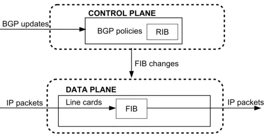
Routers are the key devices for computer networking. Thecontrol planeof a router collects and exchanges paths towards other network destinations. Thedata planeof a router stores the routing table and forwards packets accordingly to it.
The global Internet routing space is divided into Autonomous Systems (ASes) - sets of routers under a single administration [33]. The ASes are allocated with blocks of IP addresses, unified into IP prefixes. While intra-AS routing is regulated by Interior Gateway Protocols, defined internally by AS operators, the inter-routing between ASes is conducted through the external Border Gateway Protocol (BGP). BGP protocol allows an AS to advertise its network (i.e., its IP prefixes) and share paths to other networks with neighbor ASes. In addition, each AS designs its own BGP policies for path selection and advertising. BGP peer sessions result in a Routing Information Base (RIB), stored at the control plane of a router. A RIB contains the known prefixes and paths towards them. In standard routers, these prefixes and the first hops from the corresponding paths are directly installed into a Forwarding Information Base (FIB) of a router’s data plane. When a packet arrives at a router, its destination IP address should be matched against the FIB in order to obtain the next-hop, where the packet will be forwarded by the router’s forwarding engine. The IP matching at the data plane adopts the Longest Prefix Matching (LPM) rule, discussed in the following section.
Figure 2.1: The architecture of a traditional router running BGP protocol.
2.2
Longest Prefix Match (LPM) rule
According to the Longest Prefix Match rule, when an IP packet is matched against an FIB, among the prefixes matching its destination IP address the longest one must be selected. We give the formal definition below.
Definition 1. Supposepis a prefix with lengthlp in a forwarding tableT. We denotepasp1p2..plp, where
p={0,1}lp (i.e.,p
i is 0 or 1 fori = 0,1,2, ..., lp). Also suppose there is a strings ={0,1}ls, wherelsis
the length ofs. Then, according to the Longest Prefix Matching rule, we define thatpis theLongest Prefix MatchforsinT, namely,p=LP Ms(T), if and only if
1. lp≤ls
2. pis a prefix fors, i.e.p1p2..plp=s1s2..slp.
3. @p0 inT, wherep0is a prefix ofsandlp0 > lp.
We use Table 2.1 to illustrate the LPM selection. The table represents a sample FIB for IPv4 addresses with 32-bit address space. Several cases may happen during the matching process:
1. An IP destination address does not have a match in an FIB. In such a case, the packet will be dropped by the router. For example, an IP destination address that does not start with the prefix128.153.0.0/16, for example,45.56.76.120, will be discarded.
CHAPTER 2. BACKGROUND 9
Prefix Next Hop 128.153.0.0/16 1 128.153.64.0/18 2 128.153.128.0/17 3 128.153.192.0/18 4 128.153.96.0/19 5
Table 2.1: Forwarding Information Base (FIB).
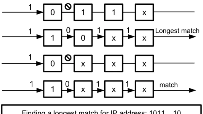
Figure 2.2: Longest Prefix Matching in TCAM.
2. An IP destination address has a single match in a FIB. In such a case, the packet will be simply forwarded to the corresponding next hop. An example of such an IP address is128.153.0.11with the match128.153.0.0/16and next-hop1.
3. An IP destination address has several matches in the table. In such a case, a match with the longest prefix length will be selected. An example of such an IP address is 128.153.124.35, that matches prefixes128.153.0.0/16,128.153.64.0/18,128.153.96.0/19. However, only the prefix128.153.96.0/19
will be selected by the data plane engine, since it is the Longest Prefix Match. Thus, the packet will be forwarded to the next-hop5.
2.3
LPM at the data plane
The amount of traffic at backbone networks may reach up to 170 Tbps in 2021 [24]. Such amounts of traffic require backbone routers to perform the LPM at a line rate. This goal is achieved by placing a FIB
in Ternary-Content Addressable Memory (TCAM) chips. Entries in TCAM should be sorted by their prefix lengths, starting with the longest prefix. The bits of an IP address are matched against all the prefixes in parallel, and the highest in position matching prefix is selected.
The design of TCAM makes it significantly more expensive than Static Random Access Memory (SRAM) or Dynamic Random Access Memory (DRAM) chips [16, 37, 54]. The cost of storage per single bit in TCAM is about 30 times more expensive than in SRAM due to the greater number of transistors [16], [54]. While a TCAM chip occupies much larger physical space than SRAM [52], the number of entries that TCAM is able to maintain is smaller compared to both SRAM and DRAM. The size of TCAM available on the market in 2016 was ranging from 1Mb to 72Mb [45]. Due to the high power demands of TCAM chips, the smaller capacity TCAM are the most popular on the market. Meanwhile, the constant increase of prefixes in the global FIB leads to TCAM overflow problem and forces network operators to upgrade their forwarding devices with bigger-size TCAM [80].
In this work, we leverage different FIB compression techniques to mitigate TCAM overflow problem. In the following chapter, we present FAQS, a FIB aggregation with Quick Selection, that compresses the forward-ing table at the smaller cost than previous FIB aggregation techniques.
Chapter 3
FIB Aggregation with Quick Selections
3.1
Introduction
FIB aggregation refers to a process, that merges FIB entries with different prefixes and the same next-hop. The rationale is that as long as data packets can be forwarded with the correct next-hop and reach their destinations correctly, it is irrelevant using which route, either the original one or an aggregated one with a different prefix length. While FIB aggregation may greatly compress the size of a FIB, the aggregation process must ensure 100% forwarding correctness and should not change the forwarding behaviors for any packet. In other words, the original and aggregated FIB tables should beForwarding Equivalent.
In the following definition, we denote:
1. LP Mω(T)as a Longest Prefix Match of an IP addressωin a tableT (see Definition 1 in Section 2.2
for a formal definition of a Longest Prefix Match).
2. NT(p)as a next-hop for a prefixpin a tableT.
Definition 2. The forwarding tables T1, T2, ..., Tm are Forwarding Equivalent, if and only if, for every
single IP addressω ={0,1}n,N
T1(LP Mω(T1)) =NT2(LP Mω(T2)) =...=NTm(LP Mω(Tm)), where
nis the length of an IP address.
In Table 3.1a FIB entriesBandChave the same next-hop value as the entryA, which fully covers IP address blocks of bothBandC. Hence, excluding entriesB andCfrom FIB table will not change the forwarding behaviors for any packets matching againstB orC, which preserves theForwarding Equivalence of the
Table 3.1: FIB aggregation process.
(a) Original FIB table
Label Prefix Next-hop A 141.92.0.0/16 1 B 141.92.64.0/18 1 C 141.92.0.0/19 1 D 141.92.192.0/19 2 E 141.92.224.0/19 2
(b) Compressed FIB table Label Prefix Next-hop
A 141.92.0.0/16 1 D 141.92.192.0/19 2 E 141.92.224.0/19 2
original and aggregated tables. Excluding entries D orE, in contrast, will not preserve theForwarding Equivalence, e.g., packets with destination IP addresses from these blocks will be forwarded to the next-hop 1 instead of 2.
A compressed FIB after aggregation is given in Table 3.1b with 3 entries, which yields the same forwarding behaviors as the original unaggregated FIB (Table 3.1a). While this is a simple example of correct FIB aggregation, more complicated cases need to be handled by an efficient aggregation algorithm. These cases include handling overlapping routes, where the majority of prefixes share the same next-hops, however, certain prefixes have different next-hops. Finally, FIB aggregation complicates BGP update handling, since these updates are designated for original prefixes, rather than aggregated prefixes.
FIB aggregation module needs to operate at the control plane of a routing device, to compress the FIB before pushing its entries into the data plane. Next, we describe the data structures we utilize for our proposedFAQS
algorithm.
3.2
Data structures
To aggregate real FIB tables with hundreds of thousand entries, the control plane’s aggregation algorithm needs to utilize compact and efficient data structures. In this work, we leverage PATRICIA tree (PT) [55] to store FIB entries. Similarly to a prefix binary tree, the nodes in such a tree correspond to prefixes (or bit strings). More specifically, the root node corresponds to the prefix with the length 0; the left or the right
CHAPTER 3. FIB AGGREGATION WITH QUICK SELECTIONS 13
Figure 3.1: PT and BT for FIB entries from Table 3.1a.
child of a node corresponds to a prefix with an appended bit 0 or 1 respectively. However, unlike a full Binary Tree (BT), which requires the prefix length difference between a parent and child node to be exactly one, the difference in a PT can be more than one. We illustrate the differences between a PT and a BT representation in Figure 3.1 for the FIB in Table 3.1. Note that we call the nodes derived from the original FIB table asREALnodes, while ancillary nodes, required to bind real nodes are called asFAKEnodes. In a BT, looking up the next-hop for a given destination address is based on its bits: starting from the first bit, if a bit is 0, then move to the left branch of the BT, otherwise, move to the right. This is a recursive process until an LPM prefix is found. In a PT, movements also stem from the difference between nodes’ levels and the bit values that reflect the branch that connects two nodes, however, a single movement can include several bits instead of a single bit.
As we can observe, the use of a PT significantly reduces memory consumption and the number of memory access times for a prefix search. This feature is especially critical for compact representation of IPv6 routing tables which have 128-bit address space.
3.3
Design
3.3.1 Static FIB aggregation
As it was mentioned above, our proposed algorithm, FIB Aggregation with Quick Selections (FAQS) uses a data structure based on the PATRICIA tree (PT) [55]. Each node in a PT has the following fields (we denote a node asn):
1. Node type, denoted by T(n). If a node was derived from an original FIB entry, the value isREAL; otherwise, if a PT node is only an ancillary node that helps to form the PT, the value is FAKE. In Figure 3.2(a),T(F)andT(G)areFAKE, and all the other nodes’ types, i.e., T(A),T(B),T(C),T(D),
T(E)areREAL.
2. Original next-hop. The next-hop value that is associated with an original FIB prefix and mapped to a PT node, denoted byO(n). For aREALnode, it is taken from the FIB; for aFAKEnode, it is derived from the original hop of its nearestREALancestor node during the top-down instantiation described below. This instantiation process is carried out during aggregation.
3. Selected next-hop. The next-hop value of a prefix after aggregation, denoted by S(n). Note that a
selected next-hopmay be different from anoriginal next-hopfor the same prefix as long as aggregated FIB has exactly the same forwarding behaviors as the original one.
4. FIB status, denoted byF(n). Indicates whether the prefix and its selected next-hop should be placed in the FIB or not after FIB aggregation.F(n)can be equal toIN FIBorNON FIB. All routes with the statusF(n)equal toIN FIBaccount for the entire aggregated FIB.
We illustrate the initial PT for the FIB from Table 3.1a in Figure 3.2(a). At this stage, the selected next-hop value and the FIB statuses of each node are unknown. In addition, theoriginal next-hopsforFAKEnodes are not defined yet. All these missing attributes are set within a single traversal that we callAggregation Round
- a depth-first traversal over the PT in a post-order manner. For the illustration, we divideAggregation Round
traversal into repeating top-down and bottom-up phases. During the top-down phases FAQS algorithm sets the original next-hop value of FAKE nodes equal to their parent’s original next-hop value. During the bottom-up phases, FAQS algorithm sets theselected next-hopfor each processed node and theFIB statuses
of its existing child nodes.
CHAPTER 3. FIB AGGREGATION WITH QUICK SELECTIONS 15
Figure 3.2: Static FIB aggregation of FIB from Table 3.1a.
I. If a nodenhas both child nodes with prefix lengths more thann’s prefix length by one, then n’s
selected next-hopvalue is equal to:
1. Its original next-hop valueO(n), if either left or right child nodes ofn has the selected next-hop value equal toO(n).
2. Left child’sselected next-hopvalue in other cases.
II.In all other cases, the selected next-hopS(n)is set equal to node’s original next-hopO(n).
Note 1:All leaf nodes’selected next-hopvalues are equal to theiroriginal next-hopvalue.
Note 2: The root node with prefix0/0is alwaysREALand has a certain defaultoriginal next-hopvalue, if its prefix does not exist in RIB.
Intuitively, the selected next-hop value of a node is equal to its original next-hop if its corresponding prefix is not fully overlapped by its children nodes’ prefixes or its original next-hop is equal to one of its children nodes’ selected next-hop values. Otherwise, when a node n’s IP space is fully covered by its children’s prefixes, we setn’s original next-hop value to its left child’s selected next-hop value. This rule allowsFAQS
to preserve forwarding equivalence of the resulting FIB since the next-hop value of a prefix changes only when (a) it was not a potential Longest Prefix Match in the original FIB table (i.e., its prefix space was fully covered by other more specific prefixes); (b) the new next-hop value of a prefixp is equal to a next-hop value one ofp’s sub-prefixes.
Label Prefix next-hop A 141.92.0.0/16 1 G 141.92.192.0/18 2
Table 3.2: FIB entries after aggregation by FAQS.
After a node’sselected next-hopvalue is set,FAQSmakes decision on theFIB statusof each of its existing child nodes according to therule B:
If the left (right) child of a nodenhas aselected next-hopvalue different fromn’s selected next-hop value
S(n), then set the status of the left (right) child toIN FIB, otherwise toNON FIB.
Note: the root node is alwaysIN FIB.
In other words, a node will be installed in the FIB if its selected next-hop is different from its parent’s selected next-hop.
Intuitively, we start aggregation from the leaf prefixes and recursively assign selected next-hops based on their original next-hops. When a child’s selected next-hop is the same as its parent’s, the child’s prefix and selected next-hop can be excluded from the aggregated FIB. The process stops at the root node, which is alwaysIN FIB. The resultant aggregated FIB will have exactly the same forwarding behaviors as the original one.
The illustration of the top-down and bottom-up phases of the initial aggregation are given in Figures 3.2(b) and 3.2(c). Post-order traversal begins with the leftmost node (nodeC) in the PT. While reaching nodeC, during the top-down phase, theoriginal next-hopvalue of theFAKEnodeFis set to 1, theoriginal next-hop
value ofF’s closestREALparentA.
Node C has no children nodes, so itsselected next-hop value is set to its original value 1. Similarly, the
selected next-hopis set for all other leaf nodes. According to the rule A, because the difference between the prefix lengths of the nodesF andCis more than 1,D’s selected next-hop value is equal to its original next-hop value. In contrast, the difference of the prefix lengths of the nodeGand its childrenDandE is equal to one. Because theselected next-hopofDandEis different fromG’soriginal next-hop,G’s selected next-hop is set to 2. Finally,A’sselected next-hopis equal to 1 (similarly to the nodeF). RegardingFIB status, according to therule B, only nodesAandGwill be installed in FIB, sinceAis the root node and its selected next-hop is not equal toG’s selected next-hop. The resulting aggregated FIB is presented in Table 3.2.
CHAPTER 3. FIB AGGREGATION WITH QUICK SELECTIONS 17
Compared with the state-of-the-artORTC-basedFIFAalgorithms [48], FAQS algorithm requires only one traversal for the static FIB aggregation. The worst-case complexity of the initial FIB aggregation is equal to
O(k∗N), where:
• kis the maximum prefix length in the FIB. In real routing tables, the length rarely exceeds 24;
• N is the number of nodes in a PT1.
FIFArequires two rounds: first, a post-order traversal in order to merge next-hops for each node, second, a pre-order traversal to choose a selected next-hop from the merged next-hop set and to set theFIB status. When aggregating real routing tables, the merged next-hop array inORTC algorithm may contain tens of elements. Moreover, each node of the PT constructed by theFAQSalgorithm has only half of the attributes, used inFIFAalgorithms. This fact also adds to the reduction of memory usage and the number of memory access times, as the number of next-hops in merged next-hop arrays can surpass 70 (see Section 3.4 for the evaluation). The complexity of FIFA algorithms isO(k∗n∗m), wherem is the maximum number of elements in the merged next-hop array.
3.3.2 Incremental FIB update handling
Through BGP updates, ASes exchange routes between each other. During spikes, the number of updates reaches several thousand. Thus it is essential to efficiently handle such updates. BGP update handling should preserve theForwarding Equivalencebetween the aggregated and original FIB tables.
BGP updates to a FIB consist of two categories:
1. Route announcements, including new routes and route changes;
2. Route withdrawals.
In the following, we describe howFAQSalgorithm handles both categories.
•Route announcements: If the announced route is a new route,FAQSalgorithm generates aREALnode with the corresponding original next-hop in the PT; if it is a route update, it simply changes the original next-hop value accordingly to the value propagated from the control plane. In order to maintain a good aggregation ratio and forwarding correctness, the aggregated FIB needs to be re-aggregated. InFAQS, two
1
portions of the PT may be affected: the subtree rooted at the updated node and the ancestors upon it. More specifically, the original next-hop, the selected next-hop and the FIB status of each node under the sub-tree need to be checked and updated if necessary. The process is similar to the procedure of the static FIB aggregation for the entire PT. Also, the selected next-hop and the FIB status of each ancestor need to be checked and refreshed if necessary to maintain forwarding correctness. The procedure seems to be tedious, however, we leverage the following three crucialoptimization techniquesto greatly reduce the overall time costs and memory access times.
1. When adding a REALnode or updating aFAKE node, if the original next-hop of this node’s parent
O(n.parent)is same as the new next-hop of the updated nodeO(n), then the top-down process can immediately terminate, since a parent’s original next-hop in the subtree rooted atndoes not change. 2. When updating the subtree, if the node type T(n)is REAL, then the top-down process can stop on
the current branch because the original next-hop of that node does not change. Similarly to the first statement, the correctness is guaranteed because allFAKEnodes’ original next-hops are derived from their nearestREALancestor’s original next-hop. When the updated node is above thisREALnoden, all original next-hops undernwill not change.
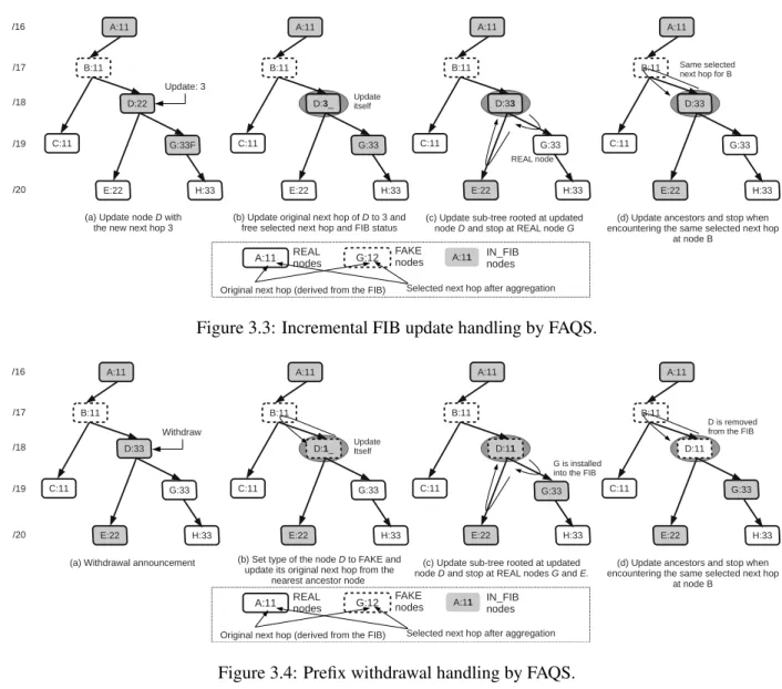
3. During the period of updating the ancestors, if the newly selected next-hop of an ancestornis the same as the old one before the update, then the bottom-up traversal can stop. Since update only happens on one branch and a parent’s selected next-hop is determined by its children’s selected next-hop, the preservation of a selected next-hop of a nodenguarantees the invariance of all nodes above it. Algorithms 4, 5 and 6 (see Appendix A) illustrate the whole process of incremental update handling. Fig-ure 3.3 demonstrates an example of a route update with a new next-hop, where the second and third opti-mization techniques are applied. In the example, the nodeDhas an update with the new next-hop3. First, the original next-hop changes to3and other fields are freed; then the update-tree process stops when en-countering aREALnodeG. After that, the update-ancestor process stops when the same selected next-hop
1is discovered at nodeB. As a result, we can observe that only a small portion of the PT has been traversed to incrementally handle the update.
In comparison with theFAQSalgorithm, the ORTC-basedFIFAalgorithm [48] requires three steps for the prefix update handling. First, it is the bottom-up post-order traversal in order to update the merged next-hop sets. During the second step, the FIFAalgorithm updates merged next-hop sets for each ancestor above the updated node. The last step is the post-order traversal of the PT, where FIFA selects the next-hop from the merged next-hop array and sets the FIB statuses as in the static aggregation algorithm. Overall, FIFA achieves the optimal aggregation ratio at the cost of a greater number of memory accesses during the
CHAPTER 3. FIB AGGREGATION WITH QUICK SELECTIONS 19
Figure 3.3: Incremental FIB update handling by FAQS.
Figure 3.4: Prefix withdrawal handling by FAQS.
optimization of the updated PT. Later in Section 3.4 we show that this causes significant delays in processing FIB updates if compared to theFAQSalgorithm.
•Route withdrawals: TheFAQSalgorithm handles the prefix withdrawals within two steps:
1. Node removal.First,FAQSlooks up the correspondingREALnode from the PT. If the node is found, thenFAQSchecks if it is removable. A removable node refers to a node, which will not affect the PT structure after its deletion. In such a case,FAQSdeletes the node and reorganizes the pointers of its parent and child. Otherwise, if the node is not removable,FAQSchanges its type toFAKEand frees the values of the original next-hop, the selected next-hop, and the FIB status.
2. PT update. Starting from the parent node of the deleted or updated node, the incremental update process will be the same as the case of route announcements. First,FAQSdoes a top-down update of the original next-hops of nodes on the subtree; next, it bottom-up updates the values of the selected next-hops and the FIB status of each node all the way to the point where a newly selected next-hop does not change. The three optimization techniques used in route announcements apply here as well.
We illustrate prefix withdrawal operation in FAQS in Figure 3.4. In the example, the prefix associated with the nodeD should be removed. First, FAQS sets the type of the node D toFAKE and updates its next-hop with the nearest ancestor’s original next-next-hop value. Since the nodeDhas two children nodes, it is an ancillary node and can not be removed from PT. Next,FAQSupdates the sub-tree rooted atDand stops at
REALnodesEandG. During this short traversal,Dsets its selected next-hop to 1 (since the prefix length difference betweenDandEis 2) andGis pushed into the FIB. Finally,FAQSupdates performs a bottom-up traversal and stops atB, sinceB’s next-hop does not change. BecauseB’s child nodeDhas the same selected next-hop,Dis removed from the FIB.
Similarly to update handling,FAQSrequires fewer memory accesses to process route withdrawals. As route withdrawals are handled identically to route updates, both operations have the same worst-case complexity,
O(k∗N), wherekis the longest prefix in the table, and N in the number of nodes in a PT. However, in reality, the number of accesses is much less, thanks to theoptimization techniques, namely, terminating the top-down traversal onREALnodes and the bottom-up traversal on the nodes that do not change their selected next-hop.
3.4
Evaluation of FAQS
We used realistic IPv4 and IPv6 routing tables from 2011 to 2016 in Route Views project [5] for the eval-uation. We collected several baseline routing tables on 01/01/2011 for both IPv4 and IPv6 and applied all following updates to obtain the aggregation results. We use AS neighbors as the next-hops for FIB tables, because local FIB interface information is not available in the dataset. Normally, the number of interfaces in a FIB is much less than the number of its neighbors. Thus our results underestimate the real FIB aggregation effects. We verified the forwarding equivalence of the aggregated and original tables with our designed tool
VeriTable [32]. We briefly describe VeriTable in the next subsection. We ran our experiment on an Intel Xeon Processor E5-2603 v3 1.60GHz machine.
We compared our FAQS algorithm against the optimal ORTC-based FIFA-S [48] aggregation algorithm. UnlikeFIFA-T, a faster version of FIFAalgorithms,FIFA-S has significantly smaller FIB bursts, which is
CHAPTER 3. FIB AGGREGATION WITH QUICK SELECTIONS 21
critical since writing operations on TCAM are slow [12].
We used the following metrics for our experiment:
1. FIB size: the total number of entries before and after aggregation. Aggregation Ratiois calculated as the ratio between the total number of the FIB entries after aggregation and before aggregation.
2. FIB aggregation time: the time spent handling all route updates by the aggregation algorithm (before pushing FIB changes into the data plane).
3. Total number of FIB changes: the total number of FIB changes that are pushed into the data plane by the aggregation module upon handling all route updates. One route update from the control plane may result in zero or more changes to the data plane FIB due to the incremental FIB aggregation process. If there is no aggregation, one route update corresponds to one FIB change.
4. FIB burst: the number of FIB changes caused by a single route update, either a route announcement or a withdrawal.
5. Peak aggregation time cost: the time spent to handle a routing announcement, that caused the heaviest FIB burst.
3.4.1 Verifying the Forwarding Equivalence with VeriTable
Verifying the equivalence of forwarding behavior of routing tables is essential for several cases. First, it is used in order to guarantee the correctness of the forwarding table in the data plane, derived from the control plane [19, 21, 68]. Second, network operators need to verify the consistency of the forwarding tables inside their networks [39, 40]. Finally, upon modification of the forwarding table due to FIB aggregation or caching techniques, the forwarding behavior of a router shall not change. Specifically for this case, we designed VeriTable [32], that is able to quickly verify the equivalence of multiple forwarding tables. The algorithm of VeriTable is built upon a theorem we prove below.
The formal definition of the Longest Prefix Matching and Forwarding Equivalence is given in Section 2.2 (Definition 1) and Section 3.1 (Definition 2) respectively.
In addition, we denote:
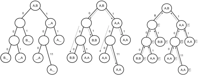
(a) Initial Joint PT (b) Joint PT after the top-down process (c) Joint PT after bottom-up verification
Nodes with non-empty labels are derived from at least one of the comparable forwarding tables, while the rest of the nodes are auxiliary nodes helping to build the data structure. During the only post-order traversal over the tree, non-empty nodes are initialized with the next-hops with respect to each forwarding table. Finally, the next-hops are compared within each node, to find
discrepancies between forwarding tables.
Figure 3.5: VeriTable algorithm.
2. NT(p)as a next-hop for a prefixpin a tableT.
Theorem 1. LetTto be a joint forwarding table, built by merging individual forwarding tablesT1, T2, ..., Tm.
Assume thatp =LP Mω(T), then we can prove that∀ω ={0,1}n,LP Mω(Ti) =LP Mp(Ti), wherenis
the length of an IP address andi= 1,2, ..., m.
Proof. Let a prefix p be p1p2..pl (l ≤ n), and ω be ω1ω2..ωn. Suppose, p = LP Mω(T), then ω =
p1p2...plωl+1..ωn. We prove the theorem using contradiction. Suppose,LP Mω(Ti) 6= LP Mp1p2..pl(Ti),
namely,LP Mp1p2...plωlωl+1..ωn(Ti)6=LP Mp1p2..pl(Ti). Then, according to the Definition 2, there exists a
different prefixp0 in the forwarding tableTi, such as its lengthlp0 > lp, andp0is a prefix forw. But then,p0
exists inT. Thus,pcan not be a Longest Prefix Match forωinT (see Definition 2), which is contradictory to the initial assumption of this theorem, thatp=LP Mω(T).
We derive VeriTable property based on the Theorem 1: comparing next-hops for eachωinT1, T2, ..., Tm
is equivalent to comparing next-hops for eachpinT1, T2, ..., Tm. Thus the new definition ofForwarding
Equivalence:
Definition 3. The forwarding tablesT1, T2, ..., TmareForwarding Equivalent, if and only if,∀ω={0,1}n, ∀p = LP Mω(T), where T is the union of T1, T2, ..., Tm,NT1(LP Mp(T1)) = NT2(LP Mp(T2)) = ...=
CHAPTER 3. FIB AGGREGATION WITH QUICK SELECTIONS 23 20 1000 2000 3000 4000 2012 2013 2014 2015 2016 Number of AS neighbors Year 4.69.184.193 (AS 3356) 12.0.1.63 (AS 7018) 85.114.0.217 (AS 8492) 144.228.241.130 (AS 1239) 147.28.7.2 (AS 3130)
Figure 3.6: AS neighbor statistics.
NTm(LP Mp(Tm)).
Based on this new definition, we designed an algorithm, that builds a joint forwarding table out of the comparable tables (using the PATRICIA Tree data structure), identifies the next-hop values of LPM prefixes in each of the comparable tables and compares those values in order to find discrepancies. The pseudo-code of the algorithm is given in Appendix E. The efficiency of VeriTable was shown in [32].
3.4.2 IPv4 results
We use five routing tables from different ASes to demonstrate the dependency of aggregation performance on the number of neighbors (i.e. the number of possible next-hops). The number of next-hops ranges from 21 to 4500. To illustrate the extreme cases, when an AS has the maximum or the minimum number of neighbors, we took AS 3356 (hop IP address4.69.184.193) and AS 3130 (hop IP address147.28.7.2). AS 3356 had almost 3000 neighbors at the beginning of 2011 and more than 4500 neighbors on 12/31/2016. For AS 3130 these numbers are 22 and 21 respectively. The number of neighbors was calculated according to the routing tables of those ASes. See Figure 3.6 for the neighborhood statistics of each AS whose IPv4 data we used in this evaluation.
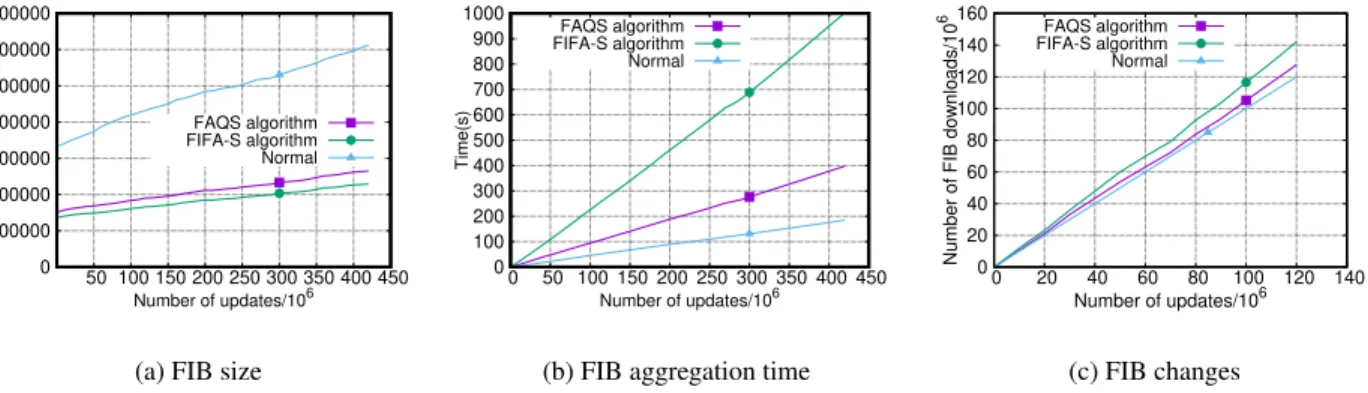
We begin with AS 3356. There are more than 426 million route updates to be handled for the 6-year period. Figure 3.7(a) shows the size of FIB aggregated byFAQSandFIFA-Salgorithms, as well as the size of the
AS nu pavg Algorithms r nc/nu taggr tpeak nb= 0 nb= 1 nb≤30 bmax m 3356 426551755 3746 FAQS 0.43 1.27 0.94µs 3.09ms 12.75% 56.21% 99.97% 1443 175MB FIFA 0.37 1.84 2.38µs 10.29ms 12.85% 64.23% 99.98% 1496 228MB 7018 782293331 2397 FAQS 0.41 1.21 0.94µs 3.09ms 16.43% 61.71% 99.99% 1854 175MB FIFA 0.34 1.78 2.06µs 8.39ms 16.38% 54.57% 99.97% 1892 229MB 8492 1037150247 1126 FAQS 0.39 1.37 0.93µs 3.27ms 6.05% 69.45% 99.97% 4268 178MB FIFA 0.32 1.90 2.33µs 12.14ms 6.40% 63.77% 99.97% 4657 233MB 1239 295214072 739 FAQS 0.42 1.28 1.09µs 3.56ms 13.18% 62.18% 99.98% 1585 175MB FIFA 0.36 1.91 2.69µs 12.68ms 13.38% 55.03% 99.97% 1952 229MB 3130 402445005 23 FAQS 0.27 1.23 0.95µs 3.26ms 14.69% 63.50% 99.98% 6464 174MB FIFA 0.20 1.68 2.04µs 16.02ms 14.91% 56.74% 99.98% 5524 228MB
(a) IPv4 routing tables
AS nu pavg Algorithms r nc/nu taggr tpeak nb= 0 nb= 1 nb≤30 bmax m
6939 122903741 2725 FAQS 0.63 1.06 0.76µs 1.27ms 7.08% 84.19% 99.99% 181 11MB FIFA 0.61 1.18 1.33µs 2.97ms 7.09% 81.19% 99.98% 258 14MB 33437 33486605 7 FAQS 0.58 0.98 0.90µs 1.42ms 17.47% 73.68% 99.99% 2447 11MB FIFA 0.56 1.11 1.43µs 2.48ms 17.46% 68.33% 99.99% 2432 14MB
(b) IPv6 routing tables
nu- the number of FIB updates;pavg- average peer number;r- aggregation ratio;nc/nu - the ratio
between the number of FIB changes and FIB updates;taggr - average aggregation time per update;tpeak
-peak aggregation time;nb- percentage of updates with burst values 0, 1 and below 30;bmax- maximum
burst value;m- memory consumption. Table 3.3: Evaluation summary.
CHAPTER 3. FIB AGGREGATION WITH QUICK SELECTIONS 25
(a) FIB size
0 100000 200000 300000 400000 500000 600000 700000 50 100 150 200 250 300 350 400 450
Number of FIB entries
Number of updates/106 FAQS algorithm FIFA-S algorithm Normal
(b) FIB aggregation time
0 100 200 300 400 500 600 700 800 900 1000 0 50 100 150 200 250 300 350 400 450 Time(s) Number of updates/106 FAQS algorithm FIFA-S algorithm Normal (c) FIB changes 0 20 40 60 80 100 120 140 160 0 20 40 60 80 100 120 140
Number of FIB downloads/10
6
Number of updates/106 FAQS algorithm FIFA-S algorithm Normal
Figure 3.7: FIB aggregation of IPv4 routing table (AS 3356).
(a) FIB size
0 100000 200000 300000 400000 500000 600000 700000 50 100 150 200 250 300 350 400 450
Number of FIB entries
Number of updates/106 FAQS algorithm FIFA-S algorithm Normal
(b) FIB aggregation time
0 100 200 300 400 500 600 700 800 900 1000 0 50 100 150 200 250 300 350 400 450 Time(s) Number of updates/106 FAQS algorithm FIFA-S algorithm Normal (c) FIB changes 0 100 200 300 400 500 600 700 0 50 100 150 200 250 300 350 400 450
Number of FIB downloads/10
6
Number of updates/106 FAQS algorithm FIFA-S algorithm Normal
Figure 3.8: FIB aggregation of IPv4 routing table (AS 3130).
original FIB during the 6-year period from 2011 to 2016. Figure 3.9(a) more clearly illustrates the margin between FIB ratio values of FAQS andFIFA-S. At the end of 2016, FAQS algorithm reduces the FIB by
57%. FIFA-Sreduces the same FIB by63%. The better aggregation ratio byFIFA-Salgorithm is achieved by additional traversals. This results in higher aggregation costs, as illustrated in Figure 3.7(b). Aggregation time costs when usingFAQSare more than twice less. On average,FAQSspends0.94µs per one FIB update. For FIFA-S algorithm the average FIB update cost was2.38µs. The peak aggregation time inFAQS is 3 times less than inFIFA(3.09msvs 10.29ms).
The smaller number of FIB changes to the FIB, the better performance. Figure 3.7(c) shows that FAQS algorithm generates 31% less number of FIB changes than that ofFIFA-Salgorithm(543,309,259 vs 786,633,132). The average number of FIB changes per update is 1.27 forFAQSand 1.84 forFIFA-S. Both algorithms have similar distribution for the size of FIB bursts as shown in Table 3.3(a). The vast majority of FIB bursts (more than 99.97%) in both algorithms consist of 30 FIB changes and less. The largest FIB burst forFAQS is 1443, which is slightly smaller thatFIFA-S(1496). Nonetheless, the update handling
(a) AS 3356 0.36 0.38 0.4 0.42 0.44 0.46 0.48 0.5 50 100 150 200 250 300 350 400 450 FIB Ratio Number of updates/106 FAQS algorithm FIFA-S algorithm (b) AS 3310 0 0.05 0.1 0.15 0.2 0.25 0.3 0.35 0.4 50 100 150 200 250 300 350 400 450 FIB Ratio Number of updates/106 FAQS algorithm FIFA-S algorithm
Figure 3.9: FIB ratio, IPv4 FIB tables.
time cost for the largest burst inFAQStakes only 30% of running time ofFIFA-S.
Since AS 3130 has a considerably smaller number of neighbors than AS 3356, it is expected that the aggre-gation ratio for its routing table is smaller. Indeed, Figure 3.9(b) shows thatFAQScan reduce the FIB size by73%andFIFA-Sby80%at most. The more compressed state of FIB may cause larger FIB bursts, as we can see from this experiment. In the case of AS 3130, the percentage of FIB bursts with less than 30 FIB updates is again negligible: 99.98% for bothFAQS andFIFA-S. The maximum FIB burst value for FAQS
was6464, while forFIFA-Sit was equal to5524. However, FAQS’s peak aggregation time cost was3.26 ms, which is less than FIFA-S’ (16.02 ms) by80%. Figure 3.8 illustrates performance ofFAQSandFIFA-S
for the next-hop AS 3130.
Table 3.3(a) presents other evaluation results of FIB aggregation for five ASes. It is interesting to observe that a large percentage (6.05%-14.91%) of FIB updates result in zero FIB changes (columnnb=0). Overall,
for IPv4 protocol,FAQSalgorithm is more than two times faster thanFIFA-Son average and is more than three times faster during peak FIB bursts.
3.4.3 IPv6 results
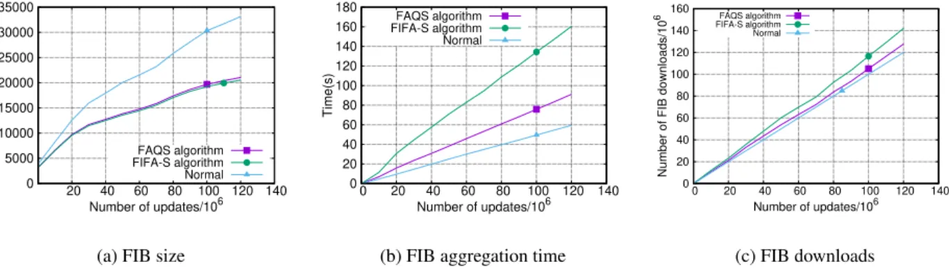
To the best of our knowledge, in this work, we for the first time evaluate IPv6 routing tables aggregation. We aggregated FIB tables from AS 6939 (hop IP address2001:470:0:1a::1) and AS 33437 (hop IP address
2001:4810::1) with the maximum and the minimum (3501 and 7 respectively) number of neighbor ASes in our collected dataset. The total number of route updates to be handled is more than 122 million. Figure 3.10
CHAPTER 3. FIB AGGREGATION WITH QUICK SELECTIONS 27
(a) FIB size
0 5000 10000 15000 20000 25000 30000 35000 20 40 60 80 100 120 140
Number of FIB entries
Number of updates/106 FAQS algorithm FIFA-S algorithm Normal
(b) FIB aggregation time
0 20 40 60 80 100 120 140 160 180 0 20 40 60 80 100 120 140 Time(s) Number of updates/106 FAQS algorithm FIFA-S algorithm Normal (c) FIB downloads 0 20 40 60 80 100 120 140 160 0 20 40 60 80 100 120 140
Number of FIB downloads/10
6
Number of updates/106
FAQS algorithm FIFA-S algorithm Normal
Figure 3.10: FIB aggregation of IPv6 routing table (AS 6939).
shows the curves of FIB size, aggregation time and the total number of FIB changes. In Figure 3.10(a), we can observe that the size of IPv6 routing tables has increased dramatically since six years back when there were only less than 5,000 entries. At the end of 2016, it has been close to 35,000. Due to the small size, the aggregation ratios for bothFAQSandFIFA-Sare around 60%, which are not as good as IPv4. SinceFIFA-S
outputs the smallest aggregated FIB,FAQS’s aggregation ratio for IPv6 is close to optimal. Remarkably, the running time ofFAQSis a much lower thanFIFA-S(90s vs 160s in Figure 3.10(b)) while they have similar aggregation ratios, which again attributes to the one-time subtree traversal with three important optimization techniques forFAQSwhileFIFA-Suses two traversals. Table 3.3(b) demonstrates results for both AS6939 and AS33437. AS33437 has only 7 next-hops, thus the aggregation ratio is better (58% vs 56% forFAQSand
FIFA-S, respectively) and the burst size is larger than the one in AS6939, because one update in AS33437 may affect a larger area of next-hops.
3.5
FAQS. Conclusion
FIB Aggregation with Quick Selections (FAQS)is a new FIB aggregation algorithm, that leverages compact data structures and three unique optimization techniques to quickly and incrementally select next-hops when handling route updates. As a result, FAQS can run up to 2.53 and 1.75 times faster for IPv4 and IPv6, respectively, than the optimal FIB aggregation algorithm while achieving near-optimal aggregation ratio. Meanwhile, it consumes much less memory and generates a significantly smaller number of FIB changes when carrying out frequent updates. The performance enhancement of the new algorithm addresses many concerns from ISPs regarding performance issues and enhances the probability to push FIB aggregation techniques further to the level of production adoption by the industry.
A Programmable FIB Caching Architecture
4.1
Introduction
FIB (or route) caching, i.e., storing popular IP prefixes in the expensive TCAM memory and the rest of it on a cheaper memory, leverages the fact that only a small part of IP prefixes carries the most of the traffic. In fact, according to the evaluation in [25], only 1.93% of FIB entries cover more than 99.5% of flows going through an ISP network. Moreover, according to Comcast, 72% of FIB entries do not carry traffic over a week [14]. The high skewness between the number of popular and unpopular routes was studied and confirmed in [41, 64]. According to these statistics, FIB caching may greatly offload the routing table in TCAM from unpopular routes, prolonging the lifetime of these expensive memory chips and reducing its operational costs.
However, FIB caching faces several challenges that impede its widespread deployment at an ISP level. First, it may result in latency issues when cache missing events occur, i.e., when an LPM lookup at TCAM fails and an additional lookup is performed on a slow memory. Moreover, simultaneous cache misses can lead to packet losses if a slow memory’s buffers are full [41]. Second, to the best of our knowledge, there is a lack of an efficient cache victim selection procedure. LRU (Least Recently Used) policy, shown to be the most optimal in [25, 41], is a software solution and can not be implemented for large prefix tables [75] on TCAM. Third, overlapping entries in a FIB cache and the secondary FIB might lead to the problem known ascache hiding.
Cache hiding is a natural problem that comes from dropping entries from a routing table that uses the LPM rule to find a match for an IP address. For example, suppose the secondary FIB contains a more specific
CHAPTER 4. A PROGRAMMABLE FIB CACHING ARCHITECTURE 29
An IP packet was forwarded to the port B instead of the port A due to the cache hiding error
Figure 4.1: Cache hiding example.
prefixpA= 128.153.64.0/18than a prefixpB= 128.153.0.0/16existing in a cache. The next-hop assigned
topAin the secondary FIB isA, while IP packets with addresses matchingpB are forwarded to a next-hop
B. In such case, a packet with IP destination address128.153.183.226matchingpAwill be forwarded to the
next-hopBrather thanA, since in the cached FIB its Longest Prefix Match is the prefixpB. We illustrate
this case in Figure 4.1. Cache hiding may be caused by:
1. Incorrect initial cache with less specific prefixes than in the secondary FIB on a slow memory;
2. A BGP prefix announcement, when a more specific prefix than another prefix existing in a cache is installed into the secondary FIB;
3. Similarly, BGP withdrawal might cause a situation when a cache contains less specific entries than in the secondary FIB.
When designing PFCA, we aimed to minimize cache-miss latencies, develop an efficient and fast cache victim selection procedure and avoid cache hiding problem. To this end, we leverage the emerging concept of the programmable data plane which we briefly describe next in this work.
Figure 4.2: Portable Switch Architecture (PSA).
4.2
Programmable data plane
The numerous emerging heavy-workload IT applications require the underlying network to quickly adapt to their demands. Thus there is a need to build more programmable and less hardware-dependent networks. OpenFlow protocol [50] and Software-Defined Networking [42] in general are important tools for build-ing programmable networks focusbuild-ing on a programmable control plane. However, OpenFlow switches are constrained with a fixed data plane configuration. Differently, the switches standardized with the Portable Switch Architecture (PSA) [58] provide the data plane with a reconfigurable parser, forwarding (or match-action) tables, and ingress/egress pipelines. PSA switches can be fully programmed with P4 data program-ming language [13]. In addition, PSA switches support packet cloning, packet recirculation, shared metadata between different stages of the packet processing pipeline and provide access to data plane registers and hash calculations.
Figure 4.2 shows the pipeline of PSA. It consists of programmable blocks, such as ingress and egress pipelines, packet parsers and deparsers; hardware-constrained blocks responsible for packet replication and buffering. The ingress and egress pipelines may contain registers and match-action tables with packet coun-ters and mecoun-ters attached to each entry. An output port is assigned to a packet when its’ headers leave the ingress pipeline. Alternatively, a packet can be cloned to multiple output ports or forwarded to the control plane. In addition, PSA data plane can be programmed to form packet digests for further analysis at the control plane.
In our work, we leverage both PSA and P4 to design an architecture for efficient FIB caching. In addition to our data plane program, we use API generated by P4 compiler to build the partial prototype of our FIB caching solution and simulate it in a P4 software switch. Note that the work on PSA compiler is still in progress, however, the design proposed in this work is compatible with the proposed PSA specification [58].