1
Static Slicing of Interprocedural Programs
A THESIS SUBMITTED IN PARTIAL FULFILLMENT OF THE
REQUIREMENTS FOR THE DEGREE OF
Bachelor of Technology
In
Computer Science and Engineering
By
Dheeraj Kumar
Roll no. 108CS053
Rakesh
Roll no. 108CS066
Under the guidance of
Prof. D.P. Mohapatra
Department of Computer Science and Engineering
National Institute of Technology
Rourkela
2012
2
CERTIFICATE
This is to certify that the thesis entitled ‘Static Slicing of Interprocedural Program’ submitted by Dheeraj Kumar and Rakesh, B.TECH students in the Department of Computer Science and Engineering, National Institute of Technology, Rourkela, India, in the partial fulfilment for the award of the degree of Bachelor of Technology, is a record of an original research work carried out by them under my supervision and guidance.
The thesis fulfils all requirements as per the regulations of this Institute and in my opinion has reached the standard needed for submission. Neither this thesis nor any part of it has been submitted for any degree or academic award elsewhere.
Date-14/05/2012 Place-Rourkela
(Prof. D.P. Mohapatra)
Department of Computer Science and Engineering
National Institute of Technology, Rourkela
India-769008
3
ACKNOWLEDGEMENT
On the submission of our Thesis report, we would like to extend our appreciation and sincere thanks to our supervisor Prof. D.P. Mohapatra, for his motivation and support throughout the project work.
We truly appreciate his esteemed guidance and encouragement from the beginning to the end of this thesis. He has been our source of inspiration throughout the thesis work and without his invaluable advice and assistance it would not have been possible for us to complete this thesis.
Dheeraj Kumar Rakesh
4
ABSTRACT
Program slicing has many applications in a software development environment such as debugging, testing, anomaly detection, program understanding and many more. The concept being introduced by Weiser and it was started with static slicing calculation. Talking about static slicing, it is a subset of statements of a program which directly or indirectly affect the values of the variables computed providing a slicing criterion. In this project, we have developed an approach for creating an intermediate representation of a program in the form of System Dependence Graph (SDG) which is to be, again taken as input for computing the slicing of a program with respect to slicing criterion. The slicing approach computes the slices with respect to a given slicing criterion. For generating the graph, we have analysed the input program, identified the tokens and finally generated the relation between tokens as data dependent or control dependent. For calculating the slice, we have used two-phase graph reachability algorithm developed by Horwitz, Reps and Binkley, which creates a graph consisting of only those nodes that are dependent on slicing criterion. Finally we have plotted a graph between time taken to create graph versus number of functions used in program. Our approach of calculating slices has been limited only to C programs.
5
Contents
1. Introduction 6 1.1 Motivation……….7 1.2 Objective……….7 2. Basic Concepts 8 2.1 Types of dependencies………..8 2.2 Types of slicing……….92.3 Types of Intermediate representation………10
3. Computing Slicing of C programs 15
3.1 Constructing intermediate representation………..15
3.2 Static slice extraction………..30
4. Implementation 32
4.1 Issues……….32
4.2 Screenshots………..33
4.3 Time taken to create graph………35
5. Conclusion and Future work 37 5.1 Conclusion………..37
5.2 Future work………..37
6
Chapter 1
Introduction
Program slicing is the computation of subset of statements of a program that may affect the values at some point of interest, can be referred to as a slicing criterion. Program slicing[12] is an important technique that has been implemented in the field of software development with applications such as debugging, testing, understanding complicated codes, anomaly detection and many others. Program slices can be of many types such as static slicing, dynamic slicing, forward slicing, backward slicing etc. Talking about static and dynamic slices, static slicing computes slices without considering the program input whereas dynamic slicing consider program input values i.e. it contains only those statements that actually affect the value of a variable.
Now to represent the input program for which we have to calculate slices with respect to given slicing criterion, we can use various kinds of graphs such as control flow graph (CFG), program dependence graph (PDG), system dependence graph (SDG), class dependence graph (CDG)[2] and many more depending upon the type of input program. For example, if we take a program that consist of only a single function with no other function call, then a PDG can be used as an intermediate representation. Similarly for an input program having function calls along with a main function or to say an Interprocedural program, we can use SDG. Weiser used the CFG for intermediate representation. This paper consider SDG approach for representing an input program and applying Horwitz et. al two phase graph reachability algorithm for calculating static slices.
7
1.1 Motivation
The kind of softwares in today’s scenario are very large in size and having a huge complexity which leads the program understanding, maintenance and testing very much difficult.
We can take an example of debugging a program in order to find the factors or to say the statements responsible for the error. Normally we have to traverse whole program line by line and to see where the error occurred which consumes time and also tedious. To resolve such issues program slicing comes forward which helps us to find the interdependence of program statements on each other. Weiser[1] first introduced the idea of program slice.
1.2 Objective
Our objective is to find the static slice of an input program by generating an intermediate representation of program and taking that graph as input to the two-phase graph reachability algorithm. To generate the intermediate representation, we do the lexical analysis of the input program and compute the dependence among the tokens generated.
8
Chapter 2
Basic Concepts
We explain all the basic terms which will be used to understand the working of computing the program slicing in the following section.
2.1 Types of Dependency
There are two types of dependencies that exist between the statements. One is data dependency and the other is control dependency.
Let us take a program to understand the types of dependencies Line 1 void seta(int m, int n)
Line 2 {int x=1; Line 3 a=m; Line 4 if(n>10) Line 5 a=x;
Line 6 printf (“%d”, a); //a is the slicing criterion }
Fig.1 Program to set value of variable a
9
a) Data Dependency
Dependencies which arises when a variable a1 defined in statement x, uses the value of other variable a2 defined in some statement y, then we say that node or statement x have data dependency on statement y.
For example, in the above program shown in Fig.1, statement 6 have data dependency on statement 3. Line 6 depends upon Line 5 which depends on Line 2 through data dependency.
b) Control Dependency
Dependencies which arises when the value of a variable a1 in statement x, controls the execution of statements where variable a2 defined.
For example, in the above program shown in Fig.1, statement 5 is control dependent on statement 4.
2.2
Types of slicing
Slicing can be explained with reference to the term slicing criterion. A slicing criterion is a pair <s, V>, where s is a program statement or to say point of interest and V is a subset of program variables.
a) Static Slicing
A static slice of a program G with respect to a slicing criterion is the set of all the statements of G that might affect the values of the variables in V at the program interest point s.
A static slice may contain statements that might not be executed during an actual run of the program.
10
b) Dynamic Slicing
A dynamic slice[5] of a program G with respect to a slicing criterion contains those statements that actually affect the slicing criterion for a given execution.
It considers the input value of variables used during execution.
Understanding in more deep the static and dynamic slice concept by applying it to the program explained in Fig.1. If we talk about static slice with respect to slicing criterion <6,a>, the statements on which the dependence exists are <1,2,3,5> whereas for dynamic slice, considering input value of n less than 10, the statements on which the dependence exists are <1,3>.
So we can deduce that the dynamic slice is a subset of static slice.
2.3 Types of Intermediate representation
The intermediate representation of a program used to compute slicing depends on the type of program we are using. For example, if we are using a single function, then a Program Dependence Graph (PDG)[8] can be used. Also, if the program contains call to many other functions inside the main function, then we will use System Dependence Graph (SDG).
a) Program Dependence Graph (PDG)
It represents those programs that consist of only one procedure as a graph, in which vertices are statements and the edges can be data dependent and control dependent.
Each PDG contains an entry vertex that represents entry into the procedure. Let us understand PDG with the help of an example program that modifies the value of variables depending on certain conditions.
11 void manipulate()
Line 1 {int a,b;
Line 2 scanf(“%d”,&a); Line 3 scanf(“%d”,&a); Line 4 if(a>b) Line 5 a=a+b; else Line 6 b=a+b; Line 7 printf(“%d”,a); Line 8 printf(“%d”,b); }
Fig. 2. Example program to manipulate value of variable
The corresponding PDG for above example in Fig. 2 is shown below
Fig. 3. PDG of example program in Fig. 2
DDEdge represents the data dependence between statements. CDEdge represents the control dependence between statements.
12
b) System Dependence Graph (SDG)
A SDG contains one procedure dependence graph for each procedure in the program. A procedure dependence graph represents a procedure as a graph, in which vertices are statements and edges are data dependent, control dependent and others to interconnect these procedural dependence graphs such as call edge, parameter edge, and summary edge.
Each procedure dependence graph contains an entry vertex that represents entry to the procedure. To allow parameter passing, an SDG associates each procedure entry vertex with formal parameters of the procedure.
Also, a SDG associates each callsite inside a procedure with a call vertex and a set of actual parameter vertices.
Types of formal and actual parameters vertices:
Actual-in vertex : For each actual parameter passed at the callsite. Actual-out vertex : For each actual parameter passed that might be
modified by the called procedure.
Formal-in vertex : For each formal parameter defined in the parameter passing of the procedure.
Formal-out vertex : For each formal parameter defined in the parameter passing that might be modified by the procedure along with the parameters returned back using return
13 An SDG connects each procedure dependence graph at call site of the calling procedure with the help of a call edge. A call edge connects a call vertex to the entry vertex of the called procedure’s dependence graph. Now the remaining part for the completion of SDG requires parameter edges. A parameter-in connects actual-in to formal-in vertices. A parameter-out connects formal-out vertex to actual-in vertex.
A summary edge represents the transitive flow of dependence across all call sites caused by data dependence.
Let us understand the SDG with the help of a sample program
Line 1 #include <stdio.h>
//calculate function
Line 2 int calculate(int first)
Line 3 {
Line 4 int res_mod;
Line 5 res_mod=first/9;
Line 6 if(res_ad>8){
Line 7 return res_mod+1;
Line 8 }
Line 9 return res_mod;
Line 10 }
Line 11 int main(int argc, char **argv) {
Line 12 int one,result;
Line 13 scanf(“enter values %d”, &one);
Line 14 result=calculate(one);
Line 15 printf(“Calculation Result is %d \one,result);
Line 16 return 0;}
Fig. 4.Example program
14
Fig.5. SDG for the program in Fig. 4
DDEdge represents the data dependence between the statements. CDEdge represents the control dependence between the statements. CALLEDGE tells that it is the calling edge from called site to entry vertex.
15
Chapter 3
Computing Static Slices of C programs
Our approach of computing static slices for a slicing criterion is limited to inter procedural C programs only. We have done slicing calculation in two phases. First phase creates the intermediate representation of the input program and the second phase computes the static slices with respect to given slicing criteria.
3.1 Constructing intermediate representation
Our Approach for creation of graph:
We have designed an approach which computes the interprocedural dependencies among the functions defined in the program. The algorithm of our approach is given below.
Algorithm:
a) Open the file.
b) WHILE not EOF do:
Put each line in INPUT_FILE[] array. ENDWHILE
c) FOR each index in INPUT_FILE[] array.
Find from which line number main () function starts. ENDFOR
16 e) FOR each line in span boundary of main function
Find function format for called function, and, if found, find actual parameters.
ENDFOR
f) FOR each function in main span Extract function name. ENDFOR
g) FOR each function name
i. Find its definition occurrence in whole program. ii. Find also its span.
ENDFOR
h) Establish call edges by comparing function definition line and its used line. i) Establish parameter-in and parameter-out edges between actual and
formal parameters if dependencies exist.
Explanation of the Algorithm:
To process Input program, we need to store tokens (variable names, function names, variable types etc.), function name, function span. So to store the tokens we used following data structures.
I. For storing input program, we have used a 2-Dimensional array which store input program line by line.
Input_progam[][].
II. For storing function call details, we have used a structure function_use_in_main, which stores details of functions used in the main program.
17 struct function_use_in_main { int line_number; char line[]; char function_name[]; char *actual_param[]; int variable_count; };
III. For storing function definition details, we have used a structure function_def_in_program, which stores details of functions defined in the program. struct function_def_in_program { int line_number; char line[]; char function_name[]; char *formal_param[]; int variable_count; int start_line; int end_line; };
Explanation of structures used:
a) In structure function_use_in_main
I. line_number stores the line number at which function is called. II. line is character array which stores the line in which function called. III. function_name stores the function name.
18 V. variable_count stores the number of actual parameter that are used in
function call.
b) In structure function_def_in_program
I. line_number store the line number at which function is defined.
II. line is character array which stores the line in which function defined. III. function_name stores the function name.
IV. formal_param[] stores the formal parameters.
V. variable_count stores the number of formal parameter that are used in function definition.
VI. start_line stores the number of line at which particular function starts. VII. end_line stores the number of line at which particular function ends.
First open the input file, read it line by line. For convenience and view point of complexity, put each line of the input program in a 2D array input_file[][]. This will remove the overhead of reading file again and again and also we can reference any line of the program by just providing the index of that line in input_file[][] array.
Execution of each program starts from main function and by processing the main function we can determine the exact control flow of whole program.
So, first find the span boundaries (start line and end line) by considering the format of function definition block as depicted in Fig. 6 of main function, then process the code between the span boundaries.
19
Fig. 6. Function Block format
For Interprocedural dependencies, first find how many functions are called in the main program. Every function call has a special format as depicted in Fig.7.
Fig. 7. Function call format
Check each line for this format and if this format is found, then extract the function name, actual parameters (parameters that are passed in function call), count of actual parameters and line number at which function is called.
Store the extracted values in structure function_use_in_main and repeat this procedure till the end boundary of main function is reached. After the processing of main function, we are having one structure function_use_in_main with complete information of each function call inside the main function.
20 After processing of main function, process the whole program except the main function. Now for finding the function call relationship, we have to find the lines where the function, which is called inside the main, is actually defined. To find function definition, compare each line for function definition format as shown in Fig. 8. If this format is found, then find the function span(start line and end line) by using the format in Fig. 1 and after then extract function name, formal parameters (parameters in function definition that refers to actual parameters in function call ), count of formal parameters and stores these values in structure function_def_in_program.
Repeat this procedure until whole program (except main function) is processed. After this processing, we are having the structure function_def_in_program, which contains actual definition information of all the functions that are defined in program.
Fig. 8. Function definition format
Now for establishment of relationship between function call and function definition, we will use the concept that function name in function definition and function call is same. So, by comparing the function_name member of structure function_use_in_main and function_def_in_program, we establish relation between function call and function definition.
To establish relation between formal parameter and actual parameter, we will use the concept that order of actual parameter in which they are passed in function call is same to the order of formal parameter in which they are used in function definition. So, comparison between parameters for each function
21 definition and function call for the same function gives the relationship between formal parameters and actual parameters.
Our approach to process each function in Program:
We have designed an approach which process each function defined in the program. In this approach we compare each line for various conditions and find the tokens on the basis of condition_type. Then find the data dependencies and control dependencies by comparing the tokens. The algorithm of our approach is given below.
Algorithm:
a) FOR each line in every procedure, do:
I. check for variable definition.
II. check for loop condition such as for, while etc.
III. check for conditional statements such as if-else etc.
IV. check for other conditions such as assignment statements, function call etc.
ENDFOR
b) IF conditions found THEN store left and right tokens. ENDIF
c) Determine dependencies between tokens by comparing them.
Explanation of the Algorithm:
To process each function, we need to have structures to store tokens for variable definition, conditional cases, loop variables, line numbers etc.
For storing tokens, we use the following data structure.
1. For storing token sequentially for each line we have used structure function_seq.
22 struct function_seq { char function_name[]; char line[]; char condition_type[]; char left_side[]; char right_side[]; int line_number; char right_tokens[][]; int right_token_count; } line[];
2. For storing Data dependency after token comparison we have used structure data_dependency.
struct data_dependency {
int line_from;
int line_to; };
3. For storing Control dependency after token comparison we have used structure control_dependency.
struct control_dependency {
int line_from;
int line_to; };
Explanation of structures used:
a) In structure function_seq:
I. function_name: character array, which stores the name of function we are processing for.
23 II. line: character array, which stores the line for which token to be
extracted.
III. condition_type: character array, which stores the condition for which token to be extracted, condition may be variable definition, loop, if condition or other(manipulation of variable, function call)
IV. left_side: character array which stores the left side of line.
V. right_side: character array which stores the right side of line. left side and right side of line are based on some condition, and this condition will be dependent on condition_type.
VI. line_number: integer type which stores the line number for which token to be extracted.
VII. right_token_count: 2 D integer type array, which stores the right tokens from the right side of line.
VIII. right_token_count: integer type which stores the total count of right token from the right part of line.
b) In structure data_dependency
I. line_from: integer_type which stores the line from which data dependency is arise.
II. line_to: integer_type which stores the line to which data dependency is arise.
c) In structure control_dependency
I. line_from: integer_type which stores the line from which control dependency is arise.
II. line_to: integer_type which stores the line to which control dependency is arise.
Now, we have information about each function in structure
function_def_in_program, so by using the start_line and end_line members of structure function_def_in_program, we can traverse each function in program including main function.
24 Here in this approach we consider that each line in a function can be one of the following conditions variable declaration loop condition conditional statements other condition i) data manipulation ii) function call
iii)variable assignment iv)start line of the function v) printf and scanf statements
So check each line for all four condition and based on condition type, extract left part and right part from the line and then extract right tokens from the right part.
1. If condition is “variable declaration” then based on the format as shown in Fig.9 we can break line into left part and right part on the basis of space occurred between the name and type of variable and if more than one variable are defined on the same type then extract all right tokens from right part.
Fig. 9. Format for variable declaration
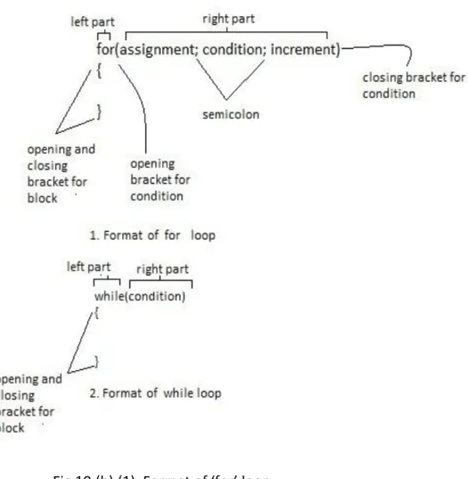
2. If condition is “loop condition” then based on the format as shown in Fig. 10(a) and Fig.10(b), break the left part and right part according to the occurrence of small opening bracket (“(”) and small closing bracket (“)”). Right part will be the part which is contained inside the small opening bracket and small closing bracket, also, find the right tokens from the right part. Apply this
25 procedure for all kind of loops (for, while, do) and store the tokens for each line in the data structure function_seq. The procedure inside the loop should be taken care of separately as this procedure depends upon the validity of condition of loop.
Fig. 10.(a). Format for do-while loop.
Fig 10.(b).(1). Format of ‘for’ loop (2). Format of ‘while’ loop
26 3. If condition is “conditional statement” then process the conditional statement same as we processed in case of loops. Take same criteria of condition for break line into left part and right part and extract the tokens from right part.
Fig.11. Format for if condition
4. If condition is “other”, then for breaking line into left part and right part take equalization sign (“=”) as a separator. because if any manipulation is done then value will be assign to right part, if any variable assignment is done then value will be assign to left part and similarly if any value return function is called then value is also assign to left part of the line as shown in figure below
a) If condition is start line of the program, then consider part between the small opening bracket (“(”) and small closing bracket (“)”) as right part and part left to the small opening bracket (“(”) will be considered as left part. Then extract right tokens from the right part.
b) If condition is scanf of printf statements, then consider part between comma (“,”) and small closing bracket (“)”) as right part and extract tokens from the right part.
The procedure inside the condition should be taken care separately as this procedure depends upon the validity of conditional statement and store the tokens for each line in data structure function_seq.
27
Fig. 12.a) Format for data manipulation b). Format for data manipulation c). Format for variable
assignment
28 Apply these conditions for each function defined in the program and store the information accordingly. At the end of these condition comparison step we are having with a data structure function_seq which contains all the tokens and information about the lines contains inside the function.
For the establishment of data dependency and control dependency we will follow the following set of rules.
Compare the right part of each line (from which dependency to be check) in function with the part(which is decidable by the following rules) of line (on which dependency to be found).
1. if condition_type for line (on which dependency to be found) is condition then compare with each right token of line.
2. if condition_type for line (on which dependency to be found) is start_line then compare with each right token of line.
3. if condition_type for line (on which dependency to be found) is scanf or printf then compare with each right token of line.
else
4. Compare with left part of line.
If matching is found in rule 1 then there will be control dependency else there will be data dependency. For rule 1 store each dependency in data structure
control_dependency by the line_number member of structure
control_dependency.
For other rules store each dependency in structure data_dependency by the line_ number member of structure data_dependency.
Each entry in the structure control_dependency and data_dependency represent the control dependency and data dependency from line_from to line_to.
29
For Creation of Graph
Now, we have four structures, which contain all the information about the interprocedural dependency and intraprocedural dependency.
funtion_use_in_main function_def_in_main control_dependency data_dependency
By using these structures, we will create the graph.
How to write graph file
For writing the graph file, first we have to understand the graph file structure. 1. Every graph file has a function as.
digraph CLDG{ }
This function contains all the nodes and the edges. 2. For node specification specify the line format as
node [color=lightblue2 , style=filled]
3. The following pattern inside this function will create a graphical representation of two nodes and one edge.
“ node one ”-> ”node two ”;
This will produce two nodes node one and node two connected by one edge. We can also modify the edge for various condition by adding the following line before the end semicolon.
30 So for creation of graph, we do the following steps
a) create a file with .graph extension. b) create a outstream for writing the file.
c) write each dependency(Interprocedural and intraprocedural) in file in the format as specified above.
For viewing the graph, we use dotty software.
3.2 Static Slice Extraction
For slicing part we use two-phase graph reachability algorithm[2] which consist of two phase to produces static slice of C programs.
Algorithm for two-phase
a) During the first pass, the algorithm traverses backward along all edges except parameter-out edges, and marks reached vertices.
b) During the second pass, the algorithm traverses backward from all vertices marked during the first pass along all edges except call and parameter-in edges, and marks reached vertices.
31
How to Backtrack the graph:
A graph file consists of so many lines. Each line consists of two parts. One part is left to “->” symbol and other part is right to “->” symbol. The left part is said to be dependent on right part.
For example, if there is a dependency 1->2->3 (1 is dependent on 2 which in turn dependent on 3) then for backtracking this dependency, first find 1 in left part of all line, once 1 is found we can easily find 2 by the help of control_dependency or data_dependency structure (depends on the condition), as these structure consists left to right dependent part in each entry. Now search for 2 in all left part, if 2 is found then we can easily find 3 as above procedure.
32
Chapter 4
Implementation
We have designed approach to compute the static slice of an interprocedural C program. In this approach, first we have taken an input program which is to be in a pre specified format. Intermediate representation of program module creates the System Dependence Graph (SDG). The SDG developed will be used as an input to the slicing algorithm to compute the static slices with respect to the slicing criterion. Two-phase graph reachability algorithm is used to compute the static slice of the input program.
Fig. 13. Flow of project model
4.1 Issues
We have taken predefined format for input program. If any other kind of format occurs while coding, a separate program can be used to convert first the input program to the specified format.
Recursion is not allowed otherwise slices computed will be wrong. In addition to that we have given only the main function of having the privilege to call other functions. So no other function can call any user defined function.
Input
Program
Intermediate
representation
of program
Static slice of
program for a
slicing criterion
33
4.2 Screenshots
34
35
Fig. 16. Screen shot representing the slice created considering slicing criteria <15,result>
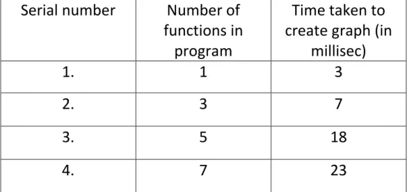
4.3 Time calculation for graph
We have plotted a graph between number of functions used in the program versus the time taken to create the graph. A inference can be made by viewing the plotted graph that as number of functions increases, the time taken to create and hence time taken to create slice also increases.
36 Table 1. Time taken to create graph
Corresponding graph is created from the data obtained in Table 1 as shown below in Fig.
Fig. 17. Graph plot between time taken vs number of function
0 5 10 15 20 25 1 3 5 7 Time of graph creation in milliseconds
Number of function contained in input program
Serial number Number of
functions in program
Time taken to create graph (in
millisec)
1. 1 3
2. 3 7
3. 5 18
37
Chapter 5
Conclusion and Future work
5.1 Conclusion
We have created a System Dependence Graph (SDG) as an intermediate representation of the input program for which we have to calculate slice. We have also plotted a graph between time taken to create an intermediate representation versus number of functions used in the program. The results show that complexity for generating the graph increases with addition in number of functions.
After generating the SDG, we have implemented slicing algorithm to calculate slices of the program based on provided slicing criterion. The slicing calculation reduces the load on the programmers to concentrate only on those parts where dependencies exist.
5.2 Future Work
Our proposed technique to create intermediate representation works only for C program. The slices that we are computing are all static. We can extend our work to create intermediate representation for object oriented programs and can apply some slicing techniques to calculate dynamic slices.
38
Chapter 6
References
[1] M. Weiser, Programmers use slices when debugging, Communications of the ACM Vol. 25 (7), pages 446-452, 1982.
[2] S. Horwitz, T. Reps, and D. Binkley. Interprocedural slicing using dependence graphs. ACM Transactions on Programming Languages and Systems, Vol.12 (1), pages 26-60, January 1990.
[3] David Binkley and Keith Brian Gallagher, “Program slicing”, Advances in Computers, Academic Press, Vol. 43, pages 1-50, 1996.
[4] K.B. Gallagher and J.R. Lyle, Using program slicing in software maintenance IEEE Transactions on Software Engineering, Vol.17, Issue-8, pages 751-761, 1991.
[5] G.B. Mund, R.Mall, S.Sarkar, “An efficient dynamic program slicing technique”, Information and Software Technology, Vol. 44, pages 123-132, 2002.
[6] G.B. Mund, R.Mall, S.Sarkar, “Computation of intraprocedural dynamic program slices”, Information and Software Technology, Vol. 45, pages 499-512, 2003.
[7] J.A. Dallal, “An Efficient Algorithm for computing all programs forward static slices”, World Academy of Science, Engineering and Technology, Vol. 16, 2006. [8] B. korel, S. Laski, “Dynamic Program Slicing”, Information Processing letters, Vol. 29(3), pages 155-163, 1988.
[8] S.Bates and S.Horwitz. “Incremental program testing using program dependence graphs”. In proceedings of the Twentieth ACM Symposium on principles of Programming languages, pages 384-396, 1993.
[9] B. korel, J. Rilling, “Program slicing in Understanding of Large Programs,” 6th International Workshop on program comprehension, pages 145-167, 1988.
39 [10]Najumudheen, R. Mall, D. Samanta, “A dependence representation for coverage testing of object-oriented programs”, Journal of Object Technology, 2010.
[11] F. Tip, “A survey of program slicing techniques”, Journal of Programming Languages, Vol. 3(3), pages 121–189, Sept. 1995.
[12] Mark Weiser, “Program Slicing”, IEEE Trans. Software Engineering Vol.16(5), pages 498-509, 1984.