IJEDR1702178 International Journal of Engineering Development and Research (www.ijedr.org) 1044
Swarada S. Muley, Sujit V. Wankhade
Assistant professor,student Department of Electrical Engneering JSPM’s BSIOTR, Wagholi. Pune. Maharashtra,India.
Abstract— the Design and simulation of Boost converter using pulse width modulation operating in continuous conduction mode is discussed in this paper. The performance and properties of sliding mode controller of Boost Converter is compared with conventional controller i.e. Proportional Integral (PI) controller. The derived controller/converter system is feasible for step up/boosting purposes, as it is exposed to significant variations and input changes.
IndexTerms: Boost converter (DC-DC), Pulse width modulation, PI Controller, sliding mode controller. (Keywords)
I. INTRODUCTION
DC-DC converter converts sources of direct current (DC) from one voltage to another voltage. There are six basic DC-DC converters. Buck, boost, buck-boost, cuk, Sepic, & zeta. DC-DC converters are nonlinear system, hence they represent a big challenge for control system. Boost converter converts an input (DC) voltage to higher output (DC) voltage by changing the duty cycle of the main switches in the Boost converter circuit. Boost converter circuits are used in battery powered devices, where the circuit requires a higher output voltage than the input voltage, e.g. laptops, mobile phones & battery powered vehicles. So, control of Boost converter is more difficult than buck converter, where ouput voltage is less than input voltage. Control of boost converter is difficult as control input appears in voltage as well as current equations.[1]
Although the boost converter is open-loop stable its convergence to an equilibrium point may be too slow for most practical applications. Hence, the control objectives are to increase speed of convergence and to make the system robust under load and input voltage variations. Such objectives are not easy to achieve because the circuit is a nonlinear. [4].
Pulse Width Modulation(PWM) is a modulation technique that conforms the width of a pulse, formally the pulse duration, based on a modulator signal information. The average value of voltage(or current) fed to the load is controlled by turning the switch between supply and load. The longer the switch is on compared to the off periods, the power supplied to the load is high. Advantage of PWM is that power loss in switching devices is very low, since When a switch is off practically there is no current, and when it is on, there is no voltage drop across switch. Power loss, being the product of voltage and current, is thus in both cases close to zero. PWM has also been used in communication systems, motor drives for fans, pumps robotic servos, electric stoves and lamp dimmers.
Sliding Mode Control or SMC is a nonlinear method of control. It alters the dynamics of any nonlinear system by application of a discontinuous control signal. State feedback control law is a discontinuous function of time. Hence it switches from one continuous structure to another. Hence sliding mode control is a variable structure control method. Discontinuous signal forces the system to slide along cross section of the system’s normal behaviour. The multiple control structures are designed so that trajectories always move toward adjacent region with a different control structure so, ultimate trajectory will not exist entirely within one control structure, but it will slide along the boundaries of control structures. The motion of system that slides along the boundaries is called sliding mode and geometrical locus consisting of the boundaries is called sliding surface.
Sliding mode
Controller
& Conventional
IJEDR1702178 International Journal of Engineering Development and Research (www.ijedr.org) 1045
II. MATHEMATICALMODELOFDC-DCBOOSTCONVERTER
The basic principle of a Boost converter consists of 2 distinct states (Fig. 1)
In the On-state, the switch S (Fig. 1) is closed, resulting in an increase in the inductor current. In the Off-state, the switch is open and the only path offered to inductor current is through the fly back diode D, the capacitor C and the load R. This results in transferring the energy accumulated during the On-state into the capacitor.
The input current is the same as the inductor current, So it is not discontinuous as in the buck converter and the requirements on the input filter are relaxed compared to a buck converter.
Fig.1 The duty cycle, for continuous conduction mode:
From the above expression it can be seen that the output voltage is always higher than the input voltage (as the duty cycle goes from 0 to 1), and that it increases with D, theoretically to infinity as D approaches 1. This is why this converter is sometimes referred to as a step -up converter.
III. MATHEMATICALMODELOFPULSEWIDTHMODULATOR
We know,TON is the time for which output is high and TOFF is the time for which output is low. Let, Ttotal be time period of waveform, such that,
Duty cycle of a square wave is defined as,
The output voltage varies with duty cycle as,
Therefore,
So, we can see from (3.4) the output voltage can be directly varied by varying the value.
L O A D Vin
D
C S
IL
IC
IJEDR1702178 International Journal of Engineering Development and Research (www.ijedr.org) 1046 If is 0, is also 0 and if the is then is or maximum. This was about theory
behind PWM.
IV. SLIDING MODE CONTROL
In control theory, sliding mode control, or SMC, is a nonlinear control method that alters the dynamics of a nonlinear system by application of a discontinuous control signal that forces the system to "slide" along a cross -section of the system's normal behavior. The state-feedback control law is not a continuous function of time. Instead, it can switch from one continuous structure to another based on the current position in the state space. Hence, sliding mode control is a variable structure control method. The multiple control structures are designed so that trajectories always move toward an adjacent region with a different control structure, and so the ultimate trajectory will not exist entirely within one control structure. Instead, it will slide along the boundaries of the control structures. Several systematic approaches for the synthesis of nonlinear sliding surfaces with suitable stabilizing properties have been investigated, using nonlinear control techniques. Sliding mode control via feedback linearization, extended linearization, and other nonlinear control methods is just a short list of examples. In those cases, the sliding surfaces are composed of nonlinear functions, which, in turn, depend on the input voltage, the load, and circuit parameters. [14].
There are some problems to be solved, such as chattering phenomena, non constant switching frequency, etc, when conventional SMC (CSMC) is used in t he power converters. [15].
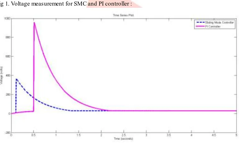
V. MODELLING AND SIMULATIONRESULTS Fig 1. Voltage measurement for SMC and PI controller :
IJEDR1702178 International Journal of Engineering Development and Research (www.ijedr.org) 1047
TABLE V.I:COMP ARISON BETWEEN OP EN LOOP RESP ONSE, SLIDING MODE CONTROLLER AND PI CONTROLLER
CONTROLLER VOLTAGE
PROFILE
SETTLING TIME
CURRENT PROFILE
Sliding mode controller
30V with linearity
0.01sec
0.1A PI controller 31v with
linearity
0.2sec 0.1A
VI. CONCLUSION
A comparison between sliding mode controller and PI controller is to be evaluated under internal losses and input voltage variation. Sliding mode controller and PI controller have same overshoot voltage but only difference is that PI controller has more voltage drop than sliding mode. PI controller has maximum settling time as compared to Sliding mode controller. In this presented work, modeling of a Boost Converter has been succes sfully done.
REFERENCES
[1] Dongyan Zhou, “Synthesis of PWM DC-DC converters”, Thesis, California Institute of Technology, 1996.
[2] L. Martinez-Salamero, A. Cid-Pastor, A. El Aroudi, R. Giral, J. Calvente, and G. Ruiz Magaz, “Sliding-mode control of DC-DC switching converters”, 18th IFAC World Congress Milano (Italy) August 28 - September 2, 2011.
[3] Siew-Chong Tan, Y. M. Lai and Chi K. Tse, “A unified approach to the design of PWM -based sliding-mode voltage controllers for basic DC-DC converters in continuous conduction mode”, IEEE Transactions on Circuits and Systems, Vol. 53, no. 8, pp 1816-1827, August 2006.
[4] Domingo Cortes, Joaquin Alvarez and Jaime Alvarez, “Robust Control of the Boost Converter”, IEEE Transactions, 2005.
[5] S. C. Tan, Y. M. Lai, C. K. Tse, and M. K. H. Cheung, “A fixed-frequency pulse-width-modulation based quasi sliding mode controller for buck converters”, IEEE Transactions Power Electronics, Vol. 20, no. 6, pp. 1379–1392, November. 2005.
IJEDR1702178 International Journal of Engineering Development and Research (www.ijedr.org) 1048 [7] Ayaz Hasan, “Design of monolithic step-up DC-DC converters with on-chip inductors”, Thesis,
Univercity of Guelph, August 2011.
[8] Sumita Dhali, P.Nageshwara Rao, Praveen Mande and K.Venkateswara Rao, “PWM-based sliding mode controller for DC-DC boost converter”, International Journal of Engineering Research and Applications (IJERA), Vol. 2, no. 1, pp. 618-623, Jan-Feb 2012.
[9] P. Sathya and Dr. R. Natarajan, “Design and implementation of 12V/24V closed loop boost converter for solar powered LED lighting system”, International Journal of Engineering and Technology (IJET), Vol. 5, no. 1, pp. 254-264, Feb-Mar 2013.
[10] D. Maksimovic, “Synthesis of PWM and quasi-resonant DC-DC power converters”, Thesis, California Institute of Technology, January 1989.
[11] Kanakasabai Viswanathan, Ramesh Oruganti and Dipti Srinivasan, “Nonlinear function controller: A simple alternative to fuzzy logic controller for a power electronic converter”, IEEE Transactions o n Industrial Electronics, Vol. 52, no. 5, pp. 1439-1448, October 2005.
[12] G. Seshagiri Rao, S. Raghu and N. Rajasekaran, “Design of feedback controller for boost converter using optimization technique”, International Journal of Power Electronics and Driv e System (IJPEDS) Vol. 3, no. 1, pp. 117-128, March 2013.
[13] Siew-Chong Tan, Y. M. Lai and Chi K. Tse, “A fast-response sliding-mode controller for boost-type converters with a wide range of operating conditions”, IEEE Transactions on Industrial Electron ics, Vol. 54, no. 6, pp. 3276-3286, December 2007.
[14] M. Castilla, L. C. de Vicuna, M. Lopez, O. Lopez, and J. Matas, “On the design of sliding mode control schemes for quantum resonant converters”, IEEE Transactions on Power Electronics, Vol. 15, no. 6, pp. 960–973, Nov. 2000.
[15] Rong-Jong Wai and Li-Chung Shih, “Adaptive fuzzy-neural-network design for voltage tracking control of a DC–DC boost converter”, IEEE Transactions on Power Electronics, Vol. 27, no. 4, pp. 2104-2115, April 2012.
[16] Mausumi Biswal, “Control techniques for DC-DC buck converter with improved performance”, Thesis, National Institute of Technology, Rourkela, March 2011.
Swarada Shrikant Mule y received M. E. (Control System) from M. B. E. S. College of Engg. Ambajogai, Maharashtra, India. and BE (Electrical, Electronics & Power Engineering) from P.E.S. College of Engineering, Aurangabad. She is currently working as Asst. Professor in Electrical Dept. with JSPM’s BSIOT R college, wagholi. Pune – 412207.