© 2017 IJSRST | Volume 3 | Issue 3 | Print ISSN: 2395-6011 | Online ISSN: 2395-602X Themed Section: Science and Technology
Review on Comparative Analysis of Induction
Generators for Wind Power System
Ashwini S. Karule
1, Chetan M. Bobade
21ME Scholar, Department of Electrical Engineering, G. H. Raisoni College Of Engineering & Management,
Amravati, Maharashtra, India
2 Assistant Professor, Department of Electrical Engineering, G. H. Raisoni College Of Engineering & Management,
Amravati, Maharashtra, India
ABSTRACT
This paper describes the performance comparison of a wind power systems based on two different induction generators as well as the experimental demonstration of a wind turbine simulator for the maximum power extraction. The two induction machines studied for the comparison are the squirrel-cage induction generator (SCIG) and the doubly fed induction generator (DFIG). The techniques of direct grid integration, independent power control, and the droop phenomenon of distribution line are studied and compared between the SCIG and DFIG systems. Both systems are modeled in Matlab/Simulink environment, and the operation is tested for the wind turbine maximum power extraction algorithm results. Based on the simulated wind turbine parameters, a commercial induction motor drive was programmed to emulate the wind turbine and is coupled to the experimental generator systems. The turbine experimental results matched well with the theoretical turbine operation.
Keywords:
Doubly Fed Induction Machines, Field-Oriented Control, Maximum Power Tracking, Wind Power System.I.
INTRODUCTION
The increasing emphasis on renewable wind energy has given rise to augmented attention on more reliable and advantageous electrical generator systems. Induction generator systems have been widely used and studied in wind power system because of their advantages over synchronous generators, such as smaller size, lower cost, and lower requirement of maintenance. The straightforward power conversion technique using squirrel-cage induction generator (SCIG) is widely accepted in fixed-speed applications with less emphasis on the high efficiency and control of power flow. However, such direct connection with grid would allow the speed to vary in a very narrow range and thus limit the wind turbine utilization and power output. Another major problem with SCIG power system is the source of reactive power; that is, an external reactive power
compensator is required to hold the distribution line voltage and prevent the whole system from overload. On the other hand, the doubly fed induction generator (DFIG) with variable-speed ability has higher energy capture efficiency and improved power quality and thus has attracted more attentions. With the advent of power electronic techniques, a back-to-back converter, which consists of two bidirectional converters and adc link, acts as an optimal operation tracking interface between generator and grid . Field-oriented control (FOC) is applied to both rotor- and stator-side converters to achieve desirable control on voltage and power. Generally, the FOC has been presented based on DFIG mathematical equations only. However, a three-phase choke is commonly used to couple the stator-side converter into the grid.
out that both stator- and rotor side converter voltages consist of a current regulation part and a cross-coupling part. First, this paper presents an experimental setup to emulate the wind turbine operation in torque control mode and thus to obtain a power operation curve for optimal power control. Second, the modeling and simulation of SCIG and DFIG wind systems are studied.
Comparison between SCIG without staticvar
compensator (STATCOM) and SCIG with STATCOM as well as DFIG system clearly indicates difference in resulted distribution line voltage. The paper is organized as follows. The wind turbine is modeled and simulated using the turbine emulator, and an expression of optimal output power versus rotor speed is proposed, the SCIG wind power system is established based on wind turbine system .the DFIG is introduced by mathematical model , indicating the relationship of voltage, flux, and torque. At last, steady-state and dynamic experiment/simulation results are presented and discussed.
II.
LITERATURE SURVEY
Induction generators are generally simulated by
means of a well-known model described by
Brereton et al. [1], based on the induction motor
equations derived by Stanley [2]. In this model the
possibility of opening the rotor circuit in order to
inject a voltage source is not taken into account,
although there are other models where it is dealt
with [3].
In this paper presents an alternative way of obtaining the mentioned model and introduces the possibility of modeling voltage sources in the rotor circuit, which can be very useful when simulating some generating schemes, such as variable speed asynchronous wind turbines.
In this paper describes the engineering and design of a doubly fed induction generator (DFIG), using back-to-back PWM voltage-source converters in the rotor circuit. A vector-control scheme for the supply-side PWM converter results in independent control of active and reactive power drawn from the supply, while ensuring sinusoidal supply current.
In this paper review the power electronics application for wind power system the possible method of using the
power electronics technology for improving wind turbine performance in power system.
This paper reviews the power electronic applications for wind energy systems. Various wind turbine systems with different generators and power electronic converters are described, and different technical features are compared. The electrical topologies of wind farms with different wind turbines are summarized and the possible uses of power electronic converters with wind farms are shown. Finally, the possible methods of using the power electronic technology for improving wind turbine performance in power systems to meet the main grid connection requirements are discussed.
Due to its many advantages such as the improved power quality, high energy efficiency and controllability, etc. the variable speed wind turbine using a doubly fed induction generator. (DFIG) is becoming a popular concept and thus the modeling of the DFIG based wind turbine becomes an interesting research topic. Fundamental frequency models have been presented but these models are often complex with significant numerical over head as the power converter block consisting of power control, rotor side and grid side converter control and DC link are often simulated in detail.
This paper develops a simple DFIG wind turbine model in which the power converter is simulated as a controlled voltage source, regulating the rotor current to meet the command of real and reactive power production. This model has the form of traditional generator model and hence is easy to integrate into the power system simulation tool such as PSS/E. Asan example, the interaction between the Ark low Bank Wind Farm and the Irish National Grid was simulated using the proposed model. The model performance and accuracy was also compared with the detailed model
developed by DIgSILENT. Considering the
simplification adopted for the model development.
Hypersim digital real-time simulator. A case study example of real-time simulation of wind turbines in a generic series compensated power system is presented.
This project A back-to-back PWM converter is used as the excitation power supply for the doubly-fed induction generator (DFIG) wind power generation of variable speed constant frequency (VSCF) The mathematical model and control strategy of converter which is connected between rotor and grid is analyzed. Grid-side converter adopts grid voltage oriented control scheme achieving the stability of DC-link voltage, unity power factor of grid-side and bi-direction flowing ability of energy. Rotor-side converter adopts the stator flux linkage oriented control scheme for achieving the maximum wind-energy capturing and adjustment of reactive power of stator. The simulation model of whole system is built. The simulation results show that the scheme utilizing back-to-back PWM converter achieves unity power factor, low distortion currents, reactive power control, sub and super-synchronous operation.
III.
METHODOLOGY
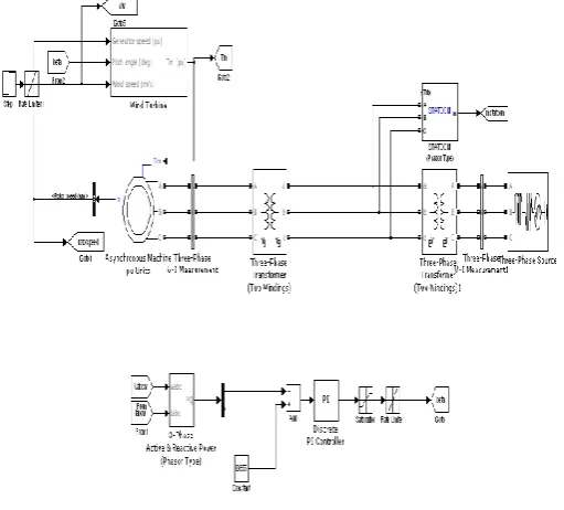
A. DFIG Wind Power System
Traditionally, the dynamic slip control is employed to fulfil the variable-speed operation in wind turbine system, in which the rotor windings are connected to variable resistor and control the slip by the varied resistance. This type of system can achieve limited variations of generator speed, but external reactive power source is still necessary. Consequently, to completely remove the reactive power compensation and to control both active and reactive power independently, DFIG wind power system is one of most popular methods in wind energy applications.
This paper reproduces DFIG model first of all and then concentrates on the controlling schemes of power converters, in which the active and reactive power are controlled independently. In particular, the stator-side converter control involving an RL series choke is proposed. Both controlling of rotor- and stator-side converter voltages end up with a current regulation part and a cross-coupling part. The wind turbine driving DFIG wind power system consists of a wound-rotor induction generator and an ac/dc/ac insulated gate bipolar transistor (IGBT)-based pulse width-modulated (PWM) converter (back-to-back converter with
capacitor dc link). In this configuration, the back-to-back converter consists of two parts: the stator-/grid-side converter and the rotor-side converter. Both are voltage source converters using IGBTs, while a capacitor between two converters acts as adc voltage source.
Figure 1. Basic Diagram of DFIG Wind Power
System
The generator stator windings are connected directly to grid (with fixed voltage and frequency of grid) while the rotor winding is fed by rotor-side converter through sliprings and brushes, at variable frequency. The control system is divided into two parts—stator-side converter control system and rotor-side converter control system. An equivalent circuit of DFIG is depicted, and the relation equations for voltage V, current I, flux Ψ, and torque Te involve.
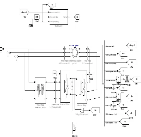
B. SCIG Wind Power System
SCIG is considered as active power reference to regulate the pitch angle while Vdis and Id is denote the distribution line-to-line voltage and phase current, and they are monitored to favor the reactive power compensation for distribution line.
Figure 2. Basic Diagram of SCIG Wind Power
System
This fairly straightforward technique was first used since it is simple and has rugged construction, reliable operation, and low cost. However, the fixed-speed essential and potential voltage instability problems severely limit the operations of wind turbine. Since SCIG is of fixed-speed generator, for a particular wind speed, the output active power is fixed as well. Thus, with the increase of wind speed, so does the output power until the nominal power is reached. The wind speed at this moment is called nominal wind speed.
IV.
CONCLUSION
This paper has presented the comparison of the wind turbine systems using SCIG and DFIG generator systems. With the experimentally investigated wind turbine model, a SCIG and a DFIG wind power systems are modeled and simulated in Matlab/Simulink. An optimal active-power-versus-rotor-speed relationship has been proposed for turbine model first, and it functions as a lookup table for tracking the maximum output active power. The SCIG system presents the need
of external reactive power source to support grid voltage, and it can keep the output power at the nominal level by pitch control but cannot accordingly change the rotor speed to achieve maximum wind power capture at different wind speeds. In contrast, the DFIG system does not need reactive power compensator to hold distribution line voltage and achieves optimal active power controlling. Both voltage control schemes for two converters consist of a current regulation part and a cross-coupling part. The turbine emulator system performs well and follows the theoretical and simulated maximum power extraction points indifferent operating conditions.
V.
REFERENCES
[1] M. Orabi, T. Ahmed, and M. Nakaoka, ―Efficient performances of induction generator for wind energy utilization,‖ inProc. 30th Annu. Conf.IEEE Ind. Elect. Soc., Nov. 2004, pp. 838–843.
[2] M. Molinas, J. A. Suul, and T. Undeland, ―Low voltage ride through ofwind farms with cage generators: STATCOM versus SVC,‖IEEE Trans.Power Electron., vol.-9 23, no. 3, pp. 1104– 1117, May 2008.
[3] Z. Chen, J. M. Guerrero, and F. Blaabjerg, ―A review of the state of theart of power electronics
for wind turbines,‖IEEE Trans. Power
Electron.,vol. 24, no. 8, pp. 1859–1875, Aug. 2009.
[4] Y. Lei, A. Mullane, and G. Lightbody, ―Modeling of the wind turbine witha doubly fed induction generator for grid integration studies,‖IEEE Trans.Energy Convers., vol. 21, no. 1, pp. 257– 264, Mar. 2006.
[5] R. Ganon, G. Sybille, and S. Bernard, ―Modeling and real-time simulation of a doubly-fed induction generator driven by a wind turbine,‖ presented at the Int. Conf. Power Systems Transients, Montreal, QC, Canada,Jun. 2005, Paper IPST05-162.
[6] H. Sun, Y. Ren, and H. Li, ―DFIG wind power
generation based on backto-back PWM
converter,‖ in Proc. IEEE Int. Conf. Mechatron. Autom.,Aug. 2009, pp. 2276–2280.
[8] S. Heier, Grid Integration of Wind Energy Conversion Systems.Hoboken, NJ, USA: Wiley, 2006.
[9] N. W. Miller, W. W. Price, and J. J. Sanchez-Gasca, ―Dynamic modelingof GE 1.5 And 3.6 wind turbine-generators,‖ GE Power Systems EnergyConsulting, Gen. Elect. Int., Inc., Schenectady, NY, USA, Oct. 2003.
[10] R. Pena, J. C. Clare, and G. M. Asher, ―Doubly fed induction generatorusing back-to-back PWM converters and its application to variable-speedwind-energy generation,‖Proc. Inst. Elect. Eng.—Elect. Power Appl.,vol. 143, no. 3, pp. 231–241, May 1996.
[11] Feijoo, J. Cidras, and C. Carrillo, ―Third order model for the doubly-fedinduction machine,‖ Elect. Power Syst. Res., vol. 56, no. 2, pp. 121– 127,Nov. 2000.
[12] T. Ghennam, E. M. Berkouk, and B. Francois, ―DC-link voltage balancingalgorithm using a space-vector hysteresis current control for three-levelVSI applied for wind conversion system,‖ inProc. Power Elect. Appl.Eur. Conf., Sep. 2007, pp. 1–10.