ISSN: 2231-5381
http://www.ijettjournal.org
Page 72Speed Control of DC Motor Using Particle
Swarm Optimization Technique by PSO
Tunned PID and FOPID
1
Anupam Aggrawal, 2Akhilesh Kumar Mishra*, 3Abdul Zeeshan
1
M.tech Scholar, 2,3, Assistant Professor
1.2.3
Department of Electrical Engineering, United College of Engineering & Research, Naini, Allahabad,Uttar Pradesh,India.
Abstract-The objective of this work is to design a speed
controller of a DC motor by finding of PID and FOPID parameters using bio-inspired optimization technique of Particle Swarm Optimization (PSO). Here, model of a DC motor is considered as a second order system for speed control. In this work bio-inspired optimization technique in controllers and their advantages over conventional methods is discussed using MATLAB/Simulink. This proposed optimization methods could be applied for higher order system also to provide better system performance with minimum errors. The main aim is to apply PSO technique to design and tune parameters of PID controller to get an output with better dynamic and static performance. The application of PSO to the PID and FOPID controller imparts it the ability of tuning itself automatically in an on-line process while the application of optimization algorithm to the PID controller makes it to give an optimum output by searching for the best set of solutions for the PID and FOPID parameters.
Keywords: - Particle Swarm Optimization; PID controller, FOPID controller; Parameter tuning.
I. INTRODUCTION
Because of to the excellent speed control behavior of a DC motor, it has been widely used in industry, in spite of its maintenance costs are higher than the induction motor. As a result, researchers have paid attention to position control of DC motor and founded several methods to control speed of such motors. Proportional–Integral-Derivative (PID) controllers have been widely used for speed and position control. In a FOPID controller, apart from the proportional (KP), Integral (KI) and derivative (KD) constants, there are
two more constants i.e, order of derivative (µ) and order of integral (λ). Hence, designing an optimum FOPID controller requires fine tuning of parametric gains {KP, KI,
KD, λ, µ}, which in return calls for real parameter
optimization in five-dimensional hyperspace. To carry out this optimization task, we chose a recently evolved swarm intelligent based Particle swarm optimization (PSO) Algorithm. Since its introduction, PSO has shown remarkable performances on wide variety of optimization
problems and a comprehensive view of applications of ABC can be found in [1]. The main advantage of PSO over other swarm intelligent methods is its simplicity in implementation, followed by a well-organized exploitation and exploration phases. These characteristics enabled ABC to be a superior contender among various evolutionary or swarm algorithms. In our current research, ABC has been chosen as optimization algorithm for finding the optimal parametric gains of FOPID controller. The design method focuses on minimization of time domain based objective function. In parallel we also designed optimal PID controller and analysis was made for both PID and FOPID controllers in terms of time domain indices and also via frequency domain stability.
The significance of fractional order control is that it is a generalization of conventional integral order control theory, which could lead to much adequate modeling and more robust control performance. The advantages of fractional order control in modeling and control design motivated renewed interest in various applications of fractional order control [6].Some MATLAB tools of the fractional order dynamic system modeling, control and filtering can be found in [7]. Reference [8] gives a fractional order PID controller by minimizing the integral of the error squares. Some numerical examples of the fractional order were presented in [9]. In reference [10], a controller was designed to ensure that the closed-loop system is robust to gain variations and the step responses exhibit aniso-damping property. For speed control of two-inertia systems, some experimental results were presented in [11] by using a fractional order PIαD controller. A comparative introduction of four fractional order controllers can be foundin [12].
ISSN: 2231-5381
http://www.ijettjournal.org
Page 73Design of fractional-order controllers based on optimization methods is one of the intensively developed methods of the present time. There are several quality control criterions to check the controller performance and to design the controller parameters by optimization methods. All of these objective functions are almost always multimodal in this case - so they have too complex geometric surface with many local extrema. In this context the choice of the optimization method is very important. A great contribution to this area have been the works (Chen, 2003; Nonje, 2005; Bettou, 2006; Cao, 2006; etc.), oriented toward the optimization-based design (Zelinka, 2002; Laciak, Kostúr, 2000; etc.). There are several quality control criterions to evaluate the controller performance and to design the controller parameters by optimization. All objective functions have too complex geometric surface with many local extrema. In this context the choice of the optimization method is very important. The methods based on classical deterministic linear or nonlinear function minimization often failed (Dorčák, 2006/a, 2006/b).The requirement for the no
steady-state error can be fulfilled by properly implementing the fractional order integrator in the controller, which provides the steady-state error cancellation. The other requirements constitute the main optimized function and the optimization constrains.
since many process plants controlled by PID controllers have similar dynamics it has been found possible to set satisfactory controller parameters from less plant information than a complete mathematical model. These techniques came about because of the desire to adjust controller parameters with a minimum of effort, and also because of the possible difficulty and poor cost benefit of obtaining mathematical models.
The PID controller calculation (algorithm) involves three separate parameters, and is accordingly sometimes called three-term control: the proportional, the integral and derivative values, denoted P, I, and D. The proportional value determines the reaction to the current error, the integral value determines the reaction based on the sum of recent errors, and the derivative value determines the reaction based on the rate at which the error has been changing. The weighted sum of these three actions is used to adjust the process via a control element. By tuning the three constants in the PID controller algorithm, the controller can provide control action designed for specific process requirements. The response of the controller can be described in terms of the responsiveness of the controller to an error, the degree to which the controller overshoots the set point and the degree of system oscillation.
In Bees Algorithm, the colony of artificial bees consists of three groups of bees: employed bees, onlookers and
scouts. First half of the colony consists of the employed artificial bees and the second half includes the onlookers. For every food source, there is only one employed bee. In other words, the number of employed bees is equal to the number of food sources around the hive. The employed bee whose the food source has been abandoned by the bees becomes a scout. The position of a food source represents a possible solution to the optimization problem and the nectar amount of a food source corresponds to the quality (fitness) of the associated solution. The number of the employed bees or the onlooker bees is equal to the number of solutions in the population. In proposed ABC-PID controller, ABC algorithm is used to optimize the gains and the values are applied into the controller of the plant. The objective of this algorithm is to optimize the gains of the PID controller for the given plant. The proportional gain makes the controller respond to the error while the integral derivative gain help to eliminate steady state error and prevent overshoot respectively.
II. MATHEMATICAL ANALYSIS OF DC MOTOR
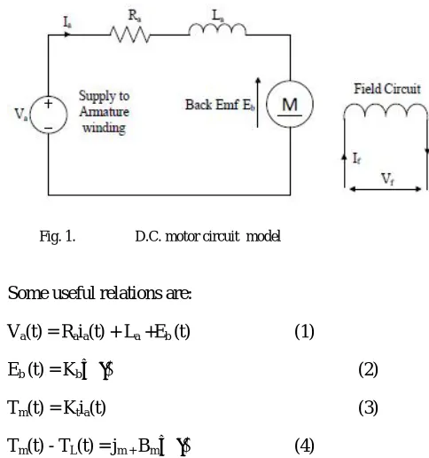
In armature control of separately excited DC motors, the voltage applied to the armature of the motor is adjusted without changing the voltage applied to the field. Figure 1 shows a DC motor equivalent model.
Fig. 1. D.C. motor circuit model
Some useful relations are:
Va(t) = Raia(t) + La +Eb (t) (1)
Eb (t) = Kbω(t) (2)
Tm(t) = Ktia(t) (3)
Tm(t) - TL(t) = jm + Bmω(t) (4)
A separately excited DC Motor mainly consists of field winding and armature winding with an independent supply. Field windings are used to excite the flux [2, 8]. A separately excited DC motor is excited by a field current If
and as a consequence an armature current Ia flows in the
ISSN: 2231-5381
http://www.ijettjournal.org
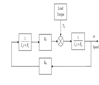
Page 74to balance the load torque at a particular speed level. Figure.1 showing the basic block diagram of DC motor model including their transfer functions. Va is the input
supply, TL is load torque and ω is angular speed.
where Va= armature voltage (Volts); Eb= Motor back Emf
(Volts); Ia= armature current (Amps); Ra= armature
resistance(ohm); La= armature inductance (H); TL= load
torque (N-m); Td= developed torque (Td); J = Moment of
Inertia (Kg/m2); B =friction coefficient of motor; angular
velocity (rad/sec).
Fig. 2. Block diagram of D.C. motor model
Speed Control of DC Motor
Substitute (3) in (2) and (4) in (5), we get
Va(t) = Raia(t) + La +Kbω(t) …(5)
Ktia(t)= jm +Bmω(t) …(6)
Taking Laplace transform of equation (6) and (5),
Va(s) = Raia(s) + sLa Ia (s ) +Kb
ωs
…(7)KtIa(s)= s jm ω(s) + Bmω(s) …(8)
There are two possible conditions:
When TL = 0
Fig. 3. Block diagram D.C. motor model when TL = 0
Figure 3 shows that the DC motor is running under no-load condition (ideal) i.e. TL = 0. Now find the transfer
function of (s) with respect to Va(s).
So, the relation between motor speed and applied voltage is given by the transfer function, = (9)
and when Va =0.
Fig. 4. Block diagram D.C. motor model when Va= 0
Figure 4 shows the DC motor model when supply voltage
(Va) is 0 and the transfer function of ω(s) is with respect to
TL(s).
Here, the relation between motor speed and load torque is given by the transfer function,
= (10)
III. SPEED CONTROL USING CLASSICAL PID
TUNING METHODS
The PID controller is the most common general purpose controller in the today’s industries. It can be used as a single unit or it can be a part of a distributed computer control system.
After implementing the PID controller, now we have to tune the controller; and there are different approaches to tune the PID parameters like P, I and D. The Proportional (P) part is responsible for following the desired set-point while the Integral (I) and Derivative (D) part account for the accumulation of past errors and the rate of change of error in the process or plant, respectively.
PID controller consists of three types of control i.e. Proportional, Integral and Derivative control
ISSN: 2231-5381
http://www.ijettjournal.org
Page 75The system transfer function in continuous s-domain are given as
ForP Kp,
I
K
i/
s
andD
K s
d
ic p d
K
G s P I D K K s
s
…(11)
1 1c p d
i
G s K T s
T s
..(12)
Where Kp is the proportional gain, Ki is the integration
coefficient and Kd is the derivative coefficient.
Ti is known as the integral action time or reset time and Td
is the derivative action time or rate time.
Fractional order control systems are described by fractional order differential equations. The FOPID controller is the expansion of the conventional PID controller based on fractional calculus.
A fractional PID controller therefore has the transfer function:
Gc(s) = Kp + Tis-λ+ Tdsδ
The orders of integration and differentiation are respectively λ and δ (both positive real numbers, not necessarily integers). Taking λ=1 and δ=1, we will have an integer order PID controller. So we see that the integer order PID controller has three parameters, while the fractional order PID controller has five
There are various tuning strategies based on an open-loop step response. While they all follow the same basic idea, they differ in slightly in how they extract the model parameters from the recorded response, and also differ slightly as to relate appropriate tuning constants to the model parameters. There are different methods, the classic Ziegler-Nichols test, and Cohen- Coon test. Naturally if the response is not sigmoid or ‘S’ shaped and exhibits overshoot, or an integrator, then this tuning method is not applicable.
This method implicitly assumes the plant can be adequately approximated by a first order transfer function with time delay.
Gp = (13)
Where K is gain, is the dead time or time delay, and T is the open loop process time constant. Once we have recorded the open loop input/output data, and subsequently measured the times T and , the PID tuning parameters can be obtained directly from the given tables for different classical methods.
Fig. 6. Block diagram of plant with variable output
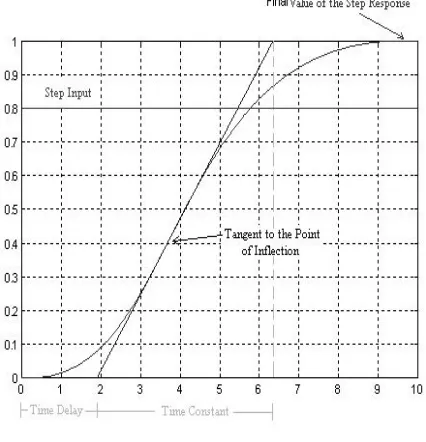
Tuning rules based on a measured step response are also called process reaction curve methods. The first (and most well-known) tuning rule of this type was suggested in 1942 [3]; in this method, the process is modeled by a FOPDT process model with
the model parameters estimated using a tangent and point method, as indicated in Figure 4.3. Simple formulae are used to define tuning parameters for PI and PID controllers. The PI controller settings are given by of the system response is obtained as shown in the figure:
Fig. 7. System responses for first order time delay transfer function
From figure we can calculate the time delay (θ) and time
constant (T) and maximum response (K=Dc gain), we can find the parameter of PID controller.
A: Ziegler-Nichols Tuning Method
The PID tuning parameters as a function of the open loop model parameters K, T and from the Process reaction curve derived by Ziegler-Nichols [2-5].
ISSN: 2231-5381
http://www.ijettjournal.org
Page 76presented by Ziegler and Nichols is based on a registration of the open-loop step response of the system, which is characterized by two parameters. First determined, and the tangent at this point is drawn. The intersections between the tangent and the coordinate axes give the parameters T and. A model of the process to be controlled was derived from these parameters. This corresponds to modeling a process by an integrator and a time delay. Ziegler and Nichols have given PID parameters directly as functions of T and. The behavior of the controller is as can be expected. The decay ratio for the step response is close to one quarter. It is
smaller for the load disturbance. The overshoot in the set point response is too large.
TABLE I Ziegler Nichols open loop method
Controller Kp Ti Td
Ziegler-Nichols Method (Open Loop)
P T/Kθ - -
PI 0.9T/Kθ θ/0.3 -
PID 1.2T/Kθ 2θ 0.5θ
B: Cohen-Coon Tuning Method
Cohen and Coon based the controller settings on the three parameters, T and K of the open loop step response. The main design criterion is rejection of load disturbances. The method attempts to position closed loop poles such that a quarter decay ration is achieved.
The PID tuning parameters as a function of the open loop model parameters K, T and from equation (14) as derived by Cohen-Coon:
TABLE II Cohen Coon open loop method
IV. PARTICLE SWARM OPTIMIZATION (PSO)
3
James Kennedy an American Social Psychologist along with Russell C.Eberhart innovated a new evolutionary computational technique termed as Particle Swarm Optimization in 1995.The approach is suitable for solving nonlinear problem. The approach is based on the swarm behavior such as birds finding food by flocking. A basic variant of the PSO algorithm works by having population (called a swarm) of candidate solution (called particles). These particles are moved around in the search-space according to a few simple formulae. The movements of the particles are guided by their own best known position in the search-space as well as the entire swarm's best known position. When improved positions are being discovered these will then come to guide the movements of the swarm. The process is repeated and by doing so it is hoped, but not guaranteed, that a satisfactory solution will eventually be discovered. Here in this technique a set of particles are put in d-dimensional search space with randomly choosing velocity and position. The initial position of the particle is taken as the best position for the start and then the velocity of the particle is updated based on the experience of other particles of the swarming population.
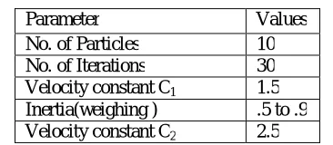
TABLE III Parameter for ABC
PSO Flowchart
The flowchart of the Artificial Bee Colony Optimization based PID control system is shown in figure 8.
Parameter Values
No. of Particles 10
No. of Iterations 30
Velocity constant C1 1.5
Inertia(weighing ) .5 to .9
ISSN: 2231-5381
http://www.ijettjournal.org
Page 77
Fig. 8. Flowchart of Artificial Bee Colony Optimization
V.SIMULINK MODEL OF DC MOTOR
The Simulink model of DC motor using is shown in Fig 8.
Fig.9. Simulink model of DC motor Fopid Tunned
The Simulink model of various tuning method for speed control of DC motor using PID controller is shown in Fig 10.
Fig.10. Simulink model of various tuning methods
The parameters used to describe the electrical and electromechanical systems are given below.
Fig.11 Simulink model of DC Motor
RESULTS AND DISCUSSION
ISSN: 2231-5381
http://www.ijettjournal.org
Page 78 Step Response Time (sec) A m p li tu d e0 1 2 3 4 5 6 7
0 0.2 0.4 0.6 0.8 1 1.2 1.4 System: ZNicolas I/O: Step to Z-Nicolas Rise Time (sec): 0.976
From: Step To: Out(1)
System: Cohen-Coon I/O: Step to Cohen-Coon Rise Time (sec): 0.547
ZNicolas Cohen-Coon
Fig.12. Speed versus Time plot with reference speed for PID tuned with Zeigler Nicholas & Cohen Coon
Step Response(Comparative Response including Closed loop)
Time (sec) A m p li tu d e
0 2 4 6 8 10 12 14 16 18 20
0 0.2 0.4 0.6 0.8 1 1.2 1.4 System: Model I/O: Step to Closed Loop Final Value: 0.0908
System: Model I/O: Step to Z-Nicolas Final Value: 1
Step Response(Comparative response of FOPID and PID Tunned by PSO)
Time (sec) A m p li tu d e
0 5 10 15 20 25
0 0.2 0.4 0.6 0.8 1 1.2 1.4
Fig.13. Speed versus Time plot with reference speed for PID tuned with Artificial Bee Colony optimization (Step response)
Table1. Comparative analysis of various tuning methods
It can be seen from the above comparison table that while using the bio-inspired technique (Particle swarm Optimization ) the overshoots obtained is zero as compared to the case when the PID Controller is was tuned via conventional methods. The settling time is also lesser in case of the Particle swarm Optimization, also the rise time is reduced. The Particle swarm Optimization FOPID controller tends to approach the reference speed faster and has, comparatively, a zero overshoot. It can be observed from Fig 11 and 12 that the Conventional PID controller have overshoot from the reference speed and attain a steady state with larger settling time.
CONCLUSION
Performance comparison of different controllers has been reviewed and it is found that Particle Swarm optimization is best among the all methods which are used for tuning the parameter of PID controller for which settling time and rise is found to be less. The conventional controllers however are not recommended for higher order and complex systems as they can cause the system to become unstable. Hence, a heuristic approach is required for choice of the controller parameters which can be provided with the help of Bio inspired methods such as Particle swarm Optimization, where we can define variables in a subjective way.
VI. ACKNOWLEDGMENT
This work was supported by Mr. Ashish Tripathi & Anukaran Khanna , Ajit Yadav( Assistant Professor). Special Thanks to all faculty members of Electrical Engineering of United College of Engineering & Research, Allahabad India, Specially Head of Department Mr. Abdul Zeeshan & Mr. Vinod Kumar Vishwkarma for their co-operation.
K P KI
LE MD
A KD ME U OVERS HOOT SETT LING TIME RISE TIM E STE ADY STA TE ERR OR CLOS ED N
A NA NA NA NA 52.0055 1.8476
1.02E +00 0.919 2 ZN 1.7
15 16.3 NA
4.5
1E-02 NA 12.0168 3.2516 9.91E
-01 0
CC
1.9 31
3.40E
+01 NA
2.8
3E-01 NA 31.5632 4.502 6.09E
-01 0
PIDPS O 50
9.690
4 NA
0.7 048
N
A 0 12.5
2.93E
-01 0
FOPI
DPSO 36 35 1 35 0.9
763 1.17 2.96
3.51E
ISSN: 2231-5381
http://www.ijettjournal.org
Page 79REFERENCES
[1] Akhilesh K. Mishra, Anirudha Narain, “Speed Control of Dc Motor Using Particle Swarm Optimization”, International Journal of Engineering Research and Technology Vol. 1 (02), 2012, ISSN 2278 - 0181
[2] Gopal K. Dubey, “Fundamentals of Electrical Drives”, Narosa Publishing House Pvt. Ltd., 2001, chap. 6.
[3] J.G. Ziegler, N.B. Nichols, “Optimization Setting for Automatic Controller”, Trans. ASME, Vol. 64,pp. 756-769, 1942.
[4] J. Kennedy, “The Particle Swarm: Social Adaptation of Knowledge”, Proceeding of the IEEE International Conference on Evolutionary Computation, ICEC1997, Indianapolis, pp. 303-308, 1997.
[5] Ozden Ercin and Ramazan Coban, “Comparison of the Artificial Bee Colony and the Bees Algorithm for PID Controller Tuning”, Innovations in Intelligent Systems and Applications (INISTA) IEEE conference, pp. 595-598, 2011.
[6] A. Oustaloup, J. Sabatier and X. Moreau, “From fractal robustness to the CRONE approach,” ESAIM, vol. 5, pp. 177-192, 1998.
[7] D.Y. Xue and Y.Q. Chen. Advanced Mathematic Problem Solution Using MATLAB, Beijing: Tsinghua University Press, 2004.
[8] Z.F. Lv, “Time-domain simulation and design of SISO feedback control systems,” Doctoral Dissertation, National Cheng Kung University, 2004.
[9] C.N. Zhao, D.Y. Xue and Y.Q. Chen, “A fractional order PID tuning algorithm for a class of fractional order plants,” Proc of the IEEE International Conference on Mechatronics and Automation, Niagara Falls, Canada, 2005, pp. 216-221.
[10] C.A. Monje, et al. “Proposals for fractional PIλDµ tuning,” The First
IFAC Symposium on Fractional Differentiation and its Applications, Bordeaux, France, 2004.
[11] C.B. Ma and Y. Hori, “Design of fractional order PID controller for robust two-inertia speed control to torque saturation and load inertia variation,” IPEMC, Xi'an, China,2003.
[12] D.Y. Xue and Y.Q. Chen, “A comparative introduction of four fractional order controllers,” Proceedings of the 4th World Congress on IntelligentControl and Automation, Shanghai, China, 2002, pp. 3228-3235.
[13] Akhilesh Kumar Mishra , Vineet Kumar Tiwari , Rohit Kumar , Tushar Verma (2013). Speed Control of DC Motor Using Artificial Bee Colony Optimization Technique.Universal Journal of Electrical and