Maximum Power Point Tracking Using Fuzzy
Logic Controller Based Cuk Converter
P.Prakash#1, M.Vigneshkumar#2, A.Vinothkumar#3, R.Thirumoorthy#4
#
Assistant Professor(s), Department of Electrical and Electronics Engineering P.A. College of Engineering and Technology, Pollachi, India
Abstract — The need for renewable energy sources is increases at present scenario because of the acute energy crisis. India plans to produce 20 Gigawatts Solar power by the year 2020, whereas we have only realized less than half a Gigawatts of our potential as of 31st October 2019. Solar energy is a vital untapped resource in a tropical country like ours. The main hindrance for the penetration and reach of solar PV systems is their low efficiency and high capital cost. In our project we examine a schematic to extract maximum obtainable solar power from a PV module using Fuzzy logic algorithm technique to obtain maximum efficiency and it is used to control the duty cycle of Cuk converter. DC to DC power electronic Cuk converter which is used to convert DC voltage from one level to another level without using transformer. Cuk converter can step up or step down the voltage according to application though Cuk converter has an inverted output but with suitable connection it provides zero ripple output voltage.
Keywords — Cuk Converter, MPPT, Fuzzy Logic Controller, DC-DC Converter.
I.INTRODUCTION
The energy which is harvested from the natural resources like sunlight, wind, tides, geothermal heat etc. is called Renewable Energy. These resources are renewable and can be naturally replenished. Therefore, for all practical purposes, these resources can be considered to be inexhaustible, unlike dwindling conventional fossil fuels. The global energy crunch has provided a renewed impulsion to the growth and development of Clean and Renewable Energy sources. Clean Development Mechanisms (CDMs) are being adopted by organizations all across the globe. Apart from the rapidly decreasing reserves of fossil fuels in the world, another major factor working against fossil fuels is the pollution associated with their combustion. Contrastingly, renewable energy sources are known to be much cleaner and produce energy without the harmful effects of pollution unlike their conventional counterparts.
The cost of conventional energy is rising and solar energy has emerged to be a promising alternative. They are abundant, pollution free, distributed throughout the earth and recyclable. PV arrays consist of parallel and series combination of
depending upon the atmospheric specifies (e.g. solar insulation and temperature). At present scenario, renewable energy sources have been given more attention in the research area as they provide excellent opportunity to generate electricity to meet the growing CONCERN over the scarcity and undesirable environmental impacts on thermal and nuclear power plants. In general, solar energy conversion systems can be classified into two categories: photovoltaic systems which convert solar energy to electricity and thermal systems which convert solar energy into heat. Photovoltaic system offers the potential to generate electricity in a clean and consistent method. However, there are still certain limitations like low conversion efficiency of PV system and converters. In order to handle this problem, it is essential to employ an approach to extract maximum power from the PV cells.
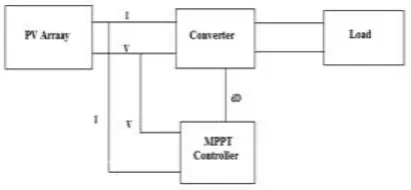
Maximum Power Point Tracking (MPPT) technique is an approach which effectively makes use of the photovoltaic cells. It extracts the maximum power from the photovoltaic cells.
Fig. 1 Typical MPPT Controller
A MPPT is applied for extracting the maximum power from the solar PV module and send out that power to the load. A DC/DC converter (step up/ step down) helps in transferring maximum power from the solar PV module to the load. A DC/DC converter acts as an interface between the load and the module as shown in Figure 1.
converter switches to guarantee that the converter operates as close as possible to the PV Maximum Power Point. [9,10]
For an efficient MPPT controller, two considerations can be made, initially by establishing an improved algorithm for tracking MPP of PV systems and then by establishing an efficient boost converter circuit which is an essential component in the controller. Many ongoing researches are mainly based on the converter circuit in order to extract maximum power from the PV panel. Some of the converter circuits used to obtain maximum power is buck converter, boost converter and Cuk converter. The operation and drawbacks of these conventional converters are discussed in the next sections.[3]
In this project, a modified Cuk converter with fuzzy logic controller based MPPT technique has been proposed to extract the maximum power from the PV panel. The proposed converter is compared with modified Cuk converter With P&O MPPT Controller and also compared with the boost converter with P&O controller in the MATLAB/Simulink environment.
II.EXISTINGTECHNIQUE
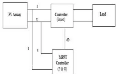
In the existing project converter used was boost converter and to control the duty cycle of converter Perturb and Observe algorithm was employed in MPPT for tracking maximum power. Under abruptly changing weather conditions (irradiance level) as MPP changes continuously, P&O takes it as a change in MPP due to perturbation rather than that of irradiance and sometimes ends up in calculating wrong MPP.
Fig. 2 Block diagram of Existing System.
However the disadvantage can be overcome by using Fuzzy logic controller algorithm. The block diagram of existing technique is shown in Figure 2. [1]
III.PROPOSEDTECHNIQUE
However the disadvantage in the existing system can be overcome by employing Fuzzy logic controller algorithm using cuk converter in proposed
technique of our project. The block diagram of proposed system is shown in Figure 3.
It will track the maximum amount of power with continuous output voltage and current and provide accurate maximum efficiency when compared to other conventional techniques.
Fig. 3 Block diagram of Proposed System.
A. An overview of MPPT
A typical solar panel converts only 30 to 40 percent of the incident solar irradiation into electrical energy. Maximum power point tracking technique is used to improve the efficiency of the solar panel. According to Maximum Power Transfer theorem, the power output of a circuit is maximum when the Thevenin impedance of the circuit (source impedance) matches with the load impedance. Hence our problem of tracking the maximum power point reduces to an impedance matching problem.
In the source side we are using a Cuk converter connected to a solar panel in order to enhance the output voltage so that it can be used for different applications like motor load or any other application. By changing the duty cycle of the Cuk converter appropriately we can match the source impedance with that of the load impedance. [2,7]
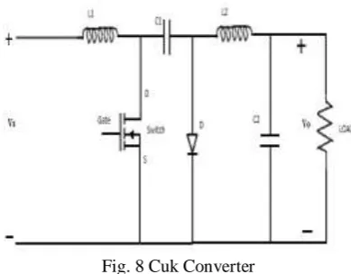
B. Cuk converter
The circuit arrangement of the Cuk converter is shown in Figure 4. Similar to the Buck-Boost converter, the Cuk converter provides an output voltage that is less than or greater than the input voltage, but the output voltage polarity is opposite to that of the input voltage.
Fig. 4 Cuk Converter Circuit Diagram.
C. Fuzzy Logic Control
Microcontrollers have made using fuzzy logic control popular for MPPT over last decade. Fuzzy logic controllers have the advantages of working with imprecise inputs, not needing an accurate mathematical model, and handling nonlinearity. Recently fuzzy logic controllers have been introduced in the tracking of the MPP in PV systems. They have the advantage to be robust and relatively simple to design as they do not require the knowledge of the exact model. They do require in the other hand the complete knowledge of the operation of the PV system by the designer. The general diagram of Fuzzy Controller is shown in the Figure 5. [5]
Fig. 5 General diagram of a Fuzzy Controller
IV.MODELLINGOFSTANDALONEPV
SYSTEM
A. Solar panel
The entire system has been modelled on MATLAB™ 2011a and Simulink™. The block diagram of the solar PV panel is shown in Figure 6. It contains the series combination of solar cell connection.
Fig. 6 Block diagram of the solar PV panel The Figure 7 shows the connection of solar cell in series in order to get the required voltage. The
inputs to the solar PV panel are temperature, solar irradiation.
Fig. 7 Connection of solar cell in series
B. MPPT Interfacing
The controlled voltage source and the current source inverter have been used to interface the modelled panel with the rest of the system and the Cuk converter which are built using the Sim Power Systems module of MATLAB.
The block diagram for the model is a simulation for the case where we obtain a varying voltage output. This model is used to highlight the difference between the power obtained on using an MPPT algorithm and the power obtained without using an MPPT algorithm. To compare the power output in both the cases stated above, the model is equipped with a manual switch as shown. When the switch is thrown to the left the circuit bypasses the MPPT algorithm and we obtain the desired power, voltage and current outputs through the respective scopes. Contrarily when the switch is thrown to the right, the embedded MPPT function block is included in the circuit and we obtain the desired outputs through the respective scopes rate. The PIC controller works towards minimizing the error between Vref and the measured voltage by varying the duty cycle through the switch. The switch is physically realized by using a MOSFET with the gate voltage controlled by the duty cycle. [4,5]
C. Cuk converter
A Cuk Converter has been used in our simulation. It finds applications in various real life scenarios like charging of battery bank, running of DC motors, solar water pumping etc. The simulation has been done for a resistive load of recharging battery and for LED light. For efficient running of a motor, we should undergo load resistance matching techniques.
Fig. 8 Cuk Converter
V.HARDWAREIMPLEMENTATION
A. Solar Panel
The source available was solar and battery. We used was solar panel rating about 10W. It consists of 72 solar cells connected in series combination. Each cell generate output voltage of 0.5V.The model of solar panel we used was MS1210.The solar panel is shown in the Figure 9. [3]
Fig. 9 Solar Panel
B. Cuk converter
The converter we used in our project was Cuk converter which generates output voltage greater than or lesser than that of the input voltage. But in our project we generate the output voltage greater than that of the input voltage of about 50V. The design of Cuk converter is shown in the Figure 10.
Fig. 10 Cuk Converter
Based on the mode of operation of Cuk converter and its derivation we had designed suitable inductor and capacitor values for this project.
The designed ratings of our project are given below
Switching frequency = 10 kHz Duty cycle = 38.7%
T = 0.1ms TON = 38.7µs
TOFF = 61.3 µs
L1 = 0.278 mH
L2 = 0.441 mH
C1 = 3.757µF
C2 = 0.3464 µF
C. Fuzzy Logic Controller
Fuzzy Logic (FL) is one of the most popular control methods which is known by its multi-rule-based variable’s consideration. This method provides faster results compared to other Artificial Intelligent control methods such as Genetic Algorithm and Neural Networks. Being fast and robust is the main reasons of choosing FL for MPPT in the current study. To implement the FL in a problem, different steps of this algorithm must be taken which are as follows. The algorithm steps are shown in the flowchart shown in Figure 11.
Fig. 11 Flowchart for Fuzzy algorithm
The input variables of the Fuzzy logic controller are created based on the equations 1 & 2
e(t) = ∆P(t) / ∆V(t) = P(t) – P(t-1) / V(t) – V(t-1) (1) e(t) = e(t) - e(t -1) (2)
1) Fuzzy systems
2) Fuzzification
The input defined in Equations 1 and 2 need to be fuzzified by some membership functions. For each inputvalue, the respective membership function returns a value of m. The max-min method was applied to extract the m from the triangle type membership function and trapezoidal type membership function.
Figure 12 depicts the membership functions for inputs e and Δe and output ΔD which is the
variation needs to beapplied to the current D value.
Fig. 12 Membership function for inputs e ,∆e, ∆D
3) Fuzzy Inference System
Fuzzy inference methods are classified in direct methods and indirect methods which have been shown in the Figure 13. Direct methods, such as Mamdani's and Sugeno's, are the most commonly used (these two methods only differ in how they obtain the outputs). Indirect methods are more complex. The process of fuzzy inference involves all of the pieces that are described in Membership Functions, Logical Operations, and If-Then Rules.
Fig. 13 Classification of inference system
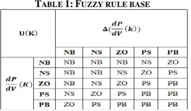
A rule base must be applied to the obtained membership function according to Mamdani. The rule table is designed and shown as Table 1.
TABLE 1:FUZZY RULE BASE
4) Mamdani’s direct method
Mamdani's method is the most commonly used in applications, due to its simple structure of 'min-max' operations. In our project too we have used mamdani’s method. The following are the steps involved in mamdani’s method.
Step 1: Evaluate the antecedent for each rule. Step 2: Obtain each rule's conclusion. Step 3: Aggregate conclusions. Step 4: Defuzzification.
5) Defuzzification
For the Defuzzification, the centroid method is applied to return a proper value for the duty cycle variation (ΔD). With the Mamdani inference scheme, the center of gravity(COG) defuzzification method is used. The defuzzified output value of the FLC must be added to a reference value of duty cycle which is considered equal to 0.5 for the current study. The result is the optimum value of D that has to be sent to the Cuk converter as a control signal.
D. Load
The load we used for our project was rechargeable battery. By using this we can able to store the energy and used whenever the need arises. Apart from battery there will be some other loads like resistive load, LED, dc motors depending upon the application requirements we can use any load.
VI.SIMULATEDRESULTANALYSIS
A. Case 1: Running the system without Fuzzy logic algorithm.
Case 1 shows that the Design of Cuk converter using Matlab had been performed using P&O algorithm which was shown in the Figure 14.
The simulated output of Cuk converter using P&O algorithm is shown in the Figure 15.
Fig. 15 Simulated output using P&O algorithm
The above simulated output is for varying input from 3V to 21V so we get the output as per this by using P&O algorithm concept.
B. Case 2: Running the system with Fuzzy logic algorithm.
This was our project in which we used Fuzzy logic controller algorithm concept along with Cuk Converter. The Matlab model of Cuk converter using Fuzzy logic algorithm is shown in the Figure 16.
Fig. 16 Matlab model of Cuk converter using Fuzzy logic concept
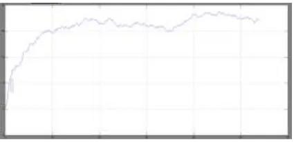
Using Fuzzy logic concept it will overcome the drawbacks of using P&O algorithm concept. The simulated output of Cuk converter using Fuzzy logic algorithm concept is shown in the Figure 17.
Fig. 17 Simulated output using Fuzzy logic concept
On comparison with case1, it shows that the output generated using Fuzzy logic controller is more with nearly of about 50v as generated output
where as using P&O concept it will generate output of about 22v.
C. Case 3: Comparative result analysis
We did simulation by using two MPPT techniques namely P&O and Fuzzy logic based concept. On viewing simulation part we conclude that fuzzy based concept will provide the robust accurate result and fewer losses. So Fuzzy based algorithm will provide an efficient and accurate result than any other algorithms. The simulated waveform for both the MPPT techniques has been given in the Figure 18 & 19.
Fig. 18 Simulated result using P&O concept
Fig. 19 Simulated result using Fuzzy logic concept
VII.CONCLUSION
REFERENCES
[1] M.S.Sivagamasundari, Dr.P.Melba Mary,V.K.Velvizhi ―Maximum Power Point Tracking For Photovoltaic System by Perturb and Observe Method Using Buck Boost Converter‖ International Journal of Advanced Research in Electrical, Electronics and Instrumentation Engineering Vol. 2, Issue 6, June 2013.
[2] Bader N. Alajmi, Khaled H. Ahmed, Stephen J. Finney, and Barry W. Williams ―Fuzzy-Logic-Control Approach of a Modified Hill-Climbing Method for Maximum Power Point in Microgrid Standalone Photovoltaic System‖ IEEE Transactions on Power Electronics, vol. 26, no. 4, April 2011.
[3] Raju .D, S.Ranga Rajan ―Simulation and Hardware Implementation of Change in Conductance MPPT controller for a solar photovoltaic system using cuk converter‖ IJRET: International Journal of Research in Engineering and Technology eISSN: 2319-1163 | pISSN: 2321-7308. [4] M.S. Aït Cheikh, C. Larbes†, G.F. Tchoketch Kebir and A.
Zerguerras ―Maximum power point tracking using a fuzzy logic control scheme‖ Revue des Energies Renouvelables Vol. 10 N°3 (2007) 387 – 395.
[5] Rasoul Rahmani, Mohammadmehdi Seyedmahmoudian, Saad Mekhilef and 1Rubiyah Yusof ―Implementation of Fuzzy Logic Maximum Power Point Tracking Controller for Photovoltaic system‖ American Journal of Applied Sciences, 10 (3): 209-218, 2013 ISSN: 1546-9239.
[6] Algazar, Mohamed & AL-monier, Hamdy & EL-halim, Hamdy & Salem, Mohamed. (2012). Maximum power point tracking using fuzzy logic control. International Journal of Electrical Power & Energy Systems. 39. 21-28. 10.1016/j.ijepes.2011.12.006.
[7] Mahammedi, Abdellatif & Abdellah, Kouzou & Hafaifa, Ahmed. (2017). Fuzzy logic controller based maximum power point tracking of PV system.
[8] Babaa, Saleh & Armstrong, Matthew & Pickert, Volker. (2014). Overview of Maximum Power Point Tracking Control Methods for PV Systems. Journal of Power and Energy Engineering. 02. 59-72. 10.4236/jpee.2014.28006. [9] P Kumar, P Prakash Harmonic Filter Design for Hvdc Lines
Using Matlab. International Journal of Computational Engineering Research, Volume 3, Issue 1, pages 12-19, 2013.