www.nat-hazards-earth-syst-sci.net/12/2811/2012/ doi:10.5194/nhess-12-2811-2012
© Author(s) 2012. CC Attribution 3.0 License.
and Earth
System Sciences
The CASA quantitative precipitation estimation system: a five year
validation study
V. Chandrasekar, Y. Wang, and H. Chen
Colorado State University, 1373 Campus Delivery, Fort Collins, CO 80523, USA
Correspondence to: V. Chandrasekar ([email protected])
Received: 27 February 2012 – Revised: 13 June 2012 – Accepted: 20 June 2012 – Published: 12 September 2012
Abstract. Flooding is one of the most common natural
haz-ards that produce substantial loss of life and property. The QPE products that are derived at high spatiotemporal res-olution, which is enabled by the deployment of a dense radar network, have the potential to improve the predic-tion of flash-flooding threats when coupled with hydrolog-ical models. The US National Science Foundation Engineer-ing Research Center for Collaborative Adaptive SensEngineer-ing of the Atmosphere (CASA) is dedicated to revolutionizing our ability to observe, understand, predict, and respond to haz-ardous weather events, especially in the lower atmosphere. CASA’s technology enables precipitation observation close to the ground and QPE is one of the important products gen-erated by the system. This paper describes the CASA QPE system built on the various underlying technologies of net-worked X-band radar systems providing high-resolution (in space and time) measurements, using the rainfall products from the radar. Evaluation of the networked rainfall prod-uct using 5 yr of data from the CASA IP-1 test bed is pre-sented. Cross validation of the product using 5 yr of data with a gauge network is also provided. The validation shows the excellent performance of the CASA QPE system with a standard error of 25 % and a low bias of 3.7 %. Examples of various CASA rainfall products including instantaneous and hourly rainfall accumulations are shown.
1 Introduction
Flooding is one of the most common natural hazards that produce substantial loss of life and property. According to the US National Academy report, floods are responsible for more deaths nationwide than any other weather phe-nomenon (NRC, 2005). Especially heavy development in
urban regions decreases the response time of urban water-sheds to rainfall and increases the chance of localized flood-ing events over a small spatial domain (Maki et al., 2008). The scales of urban floods are fairly small and intense and have a large temporal variability with fast response time. Successful monitoring of urban floods requires high spa-tiotemporal resolution and accurate precipitation estimation because of the rapid flood response as well as the complex hydrologic and hydraulic characteristics in an urban environ-ment.
The CASA (Collaborative Adaptive Sensing of the At-mosphere) is a US National Science Foundation Engineer-ing Research Center dedicated to revolutionizEngineer-ing our abil-ity to observe, understand, predict, and respond to hazardous weather events, especially in the lower atmosphere. This cen-ter has pursued an innovative, densely networked, sensing paradigm, called DCAS (Distributed Collaborative Adaptive Sensing), to overcome the resolution and coverage limita-tions of traditional weather radars using lower cost, densely networked radar systems (McLaughlin et al., 2005). The DCAS radar network is capable of high-resolution observa-tion over a large coverage area (Chandrasekar et al., 2008). The network centric sensing paradigm greatly improves the system capability and measurement accuracy (Junyent and Chandrasekar, 2009). By reducing the maximum range and operating at X-band, one can ensure good cross-range res-olution with a small-size antenna and keep the radar beam closer to the ground. The individual sensing node can be con-structed from small-size radar units that are easily amenable to ubiquitous urban deployment. A recent National Academy study has explained the salient features of the DCAS system for complex terrain (NRC, 2008).
X-band dual-polarization radar network has been in opera-tion in Oklahoma, which is referred as the IP1 (Integrative Project 1). Dual polarization radar-based technologies have been implemented for real-time mitigation of rain attenua-tion. Also the rainfall estimation using specific differential propagation phase (Bringi and Chandrasekar, 2001),Kdp, in rain is more sensitive at X-band compared to lower frequen-cies such as S- or C-band, as long as the radar return sig-nals are not attenuated fully in rain. Use ofKdp for produc-ing rainfall products makes it immune to absolute calibration errors and also more accurate than the tradition reflectivity-rainfall relations (Bringi and Chandrasekar, 2001). One of the major challenges of usingKdpis that it is derived as the slope of a phase quantity. This poses two challenges: namely, the range resolution of a slope is not as good as the point measurements, and the slope estimation is highly sensitive to phase noise. Wang and Chandrasekar (2010) have devel-oped a robustKdpestimation procedure that overcomes these problems and has contributed significantly to the progress of Kdpestimation at X-band frequencies.
This paper describes the CASA Quantitative Precipitation Estimation (QPE) system built on the various underlying technologies of networked X-band radar systems providing high-resolution (in space and time) measurements, using the rainfall products from the radar. Evaluation of the networked rainfall product using 5 yr of data from the CASA IP-1 test bed is presented. Cross validation of the product using 5 yr of data with a gauge network is also provided. Examples of various CASA rainfall products including instantaneous and hourly rainfall accumulations are shown. The paper is orga-nized as follows. Section 2 describes the features of the net-worked radar system for rainfall estimation, whereas Sect. 3 describes the CASA X-band radar network. The algorithmic aspects of the dual polarization radar rainfall estimation are described in Sect. 4, and the architecture and the commu-nication aspects of the CASA QPE system are described in Sect. 5. Section 6 presents samples of the QPE system prod-ucts and cross validation with gauge network. Section 7 sum-marizes the important features of the CASA QPE system.
2 Rainfall mapping using dense radar network
QPE is one of the key products that will drive the hydro-logic models for flood monitoring. High-resolution rainfall mapping over a large area with frequent update is the fun-damental strength of radar in this type of applications. In urban environments, the replacement of vegetation by im-permeable surface and the construction of drainage networks reduce the response time of urban watersheds to rainfall but also increase the peak discharge volumes. Road, channels, buildings and other structures modify the hydrologic and hy-draulic characteristics and potentially increase the chance of localized flooding events. Predication of lumped discharge
from the target basin is not sufficient in this case for efficient flood warning and prevention.
The spatial resolution of the QPE depends on the radar parameters such as cross-range resolution, and the temporal resolution depends on the scan strategy. The CASA system of radars maintains a system heartbeat of 30 s, and after fin-ishing two low level full 360 degree scans, conducts adaptive scans at different elevations depending on the location of the echo. The accuracy of radar QPE relies both on the radar system, such as beamwidth and sidelobe, and on the environ-mental factors, such as clutter and storm variability. Radar beam can overshoot the lower part of atmosphere due to the Earth’s curvature or blockage due to local terrain. Radar ob-servations of rainfall can also be contaminated by hail, melt-ing hydrometeor particles, and/or ground clutter. In addi-tion, in urban environments, strong clutter is expected due to scattering from buildings in the neighborhood, which act as perfect reflectors when radar is steered down low. In addi-tion, radar calibration errors and anomalous propagation also contaminate rainfall rate estimation. We refer to Saltikoff et al. (2010), for a summary of the factors leading to the quality assurance of weather radar data for QPE. In this research, the main parameter used for rainfall estimation is specific differ-ential propagation phase (Kdp).
2.1 Spatial resolution
always be some overlap. A detailed analysis of the sampling volume (or voxel) resolution as a function of beam width, network topology and degree of overlap can be found in Jun-yent and Chandrasekar (2009).
2.2 Temporal resolution
High temporal resolution real-time rainfall product genera-tion is required in order to track fast moving or evolving precipitation events to predict the threats at the same time scale in order to elicit quick response. The current NEXRAD observations are updated every 5∼6 min, collecting vol-ume information that can be used for many applications, be-yond QPE. For example, the volume information and verti-cal profile are used to compute nowcasting as well as storm growth/decay trend measurement. Because radar measures the instantaneous rainfall rate, coarse temporal update rate likely leaves substantial sampling gaps in radar QPE for the cases of fast moving storms. Small sampling interval will be particularly valuable in the extreme rain storms. It only takes tens of minutes for an urban basin to reach its peak discharge from dry condition. As flood monitoring pinpoints down to specific blocks, the temporal variability is even higher and a sampling at 5∼6 min can miss the local peaks. For short-range radar, flexible waveforms and agile scan strategy can be adopted. In a dense radar network, scan patterns can be co-ordinated in an automatic and adaptive manner in response to the detected weather phenomena. For example, a full volume scan can be performed when a widespread shallow storm is present, whereas a narrower sector scan can be performed at multiple elevation angles to observe the vertical structure when deep convective storms are present. The CASA scan strategy systems are described in Zink et al. (2010).
2.3 Beam height
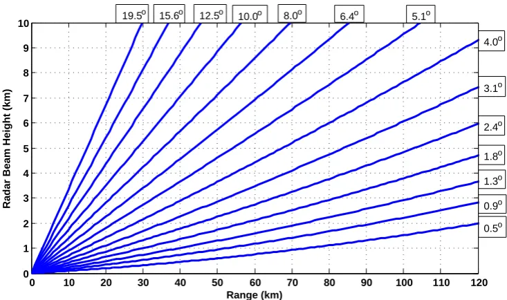
Radar measurement and rainfall estimates will be closer to the ground if they are obtained at lower heights. The radar beam also needs to be contained below bright bands or melt-ing layers and above the significant mainlobe clutter to avoid QPE biases (Zhang and Qi, 2010). The Earth’s curvature and the blockage by the local terrain can even prevent the cover-age of raining regions of interest. The lowest beam height de-pends on radar range and the lowest available elevation angle. At long range, the beam height becomes extremely high be-cause of the Earth’s curvature, e.g., nearly 5.3 km at 300 km range even at 0◦elevation angle. In addition, the current reg-ulations limit the lowest elevation angle used by NEXRAD to 0.5◦, that is, one-half the antenna beamwidth. For good radar QPE, we prefer to have the lowest beam height to be kept around 1 km. We choose the lowest useful height free of clutter contamination. While it is useful to choose the lowest height, one should be careful to avoid clutter contamination. Figure 1 shows the beam height as a function of the range from the radar, for short ranges using the 4/3 Earth curvature
model. It can be seen from Fig. 1 that 1 km height observa-tion can be achieved at 1◦elevation angle if the maximum range is limited to 50 km.
2.4 Sensitivity
The sensitivity of weather radar is directly proportional to the transmit power and inversely related to the square of radar range. Long duration light rain is not an apparent threat to an urban watershed, because the drainage can discharge the runoff in time. When using gauge measurements to validate radar QPE, the gauge may not respond well to light rain ei-ther. For example, a tip bucket rain gauge of 0.254 mm per bucket will not tip in a single 5-min interval for 2.5 mm hr−1 rainfall, which is approximately translated to 30 dBZ for radar reflectivity or 0.1 deg km−1 for the specific differen-tial propagation phase. However, for X-band radar systems, an extra margin needs to be allocated for the transmit power budget to compensate for the rain attenuation. Statistically, rain attenuation is more likely to be higher at longer propa-gation paths. Altogether, short-range radar largely relaxes the constraint on sensitivity. Extensive studies have been con-ducted for rain attenuation margin needed for communica-tion systems at higher elevacommunica-tion angles. However, data at very low elevations such as zero and few degrees are rare. Chan-drasekar et al. (2009) have shown that, for the South Central US such as Oklahoma and Texas area, the attenuation mar-gin needed for X-band radars is about 12 dB. This marmar-gin will change with different climatic region. For example, it is likely to be smaller for the western coast of the US.
2.5 Clutter mitigation
The radar reflectivity for clutter echo can be written as Zec<dBZ>
=2f (α)+σ0<dB>+C+10 log10Ac<km 2> Vc<km3>
(1) where f(α)is the sidelobe pattern at clutter incidence angle, σ0is surface backscattering coefficient,C is the radar con-stant,Acis the beam illuminated area, andVcis the effective
radar resolution volume. At low grazing angles,Ac is
0 10 20 30 40 50 60 70 80 90 100 110 120 0
1 2 3 4 5 6 7 8 9 10
Range (km)
Radar Beam Height (km)
3.1o
2.4o
1.8o
1.3o 4.0o 5.1o
8.0o 10.0o
12.5o 6.4o 19.5o 15.6o
0.9o 0.5o
Fig. 1. Beam height vs. radar range at the elevation angles corresponding to one of the scan strategies of WSR-88D (VCP-12).
clutter filtering procedure that is very close to the GMAP technique (Siggia and Passarelli, 2004), except that it oper-ates on the dual-polarized signals (Bharadwaj et al., 2010). It should be noted here that, since the main product used for rainfall isKdp, clutter filtering of dual polarized measure-ments is important. With a combination of networked radar application and advanced clutter filtering, the impact of clut-ter on rainfall estimation is mitigated in the CASA QPE sys-tem.
3 X-band dual-polarization radar networks
A distributed collaborative adaptive sensing (DCAS) sys-tem dynamically utilizes networked short-range radar units to achieve high spatiotemporal resolution (Junyent and Chan-drasekar, 2009). In DCAS networks, distributed short-range radars are not only densely deployed, but the resources are also dynamically and adaptively allocated according to the storm evolution and user needs, achieving higher resolution in both space and time. All the radar nodes are operated collaboratively to provide the sensing functionality for the entire network coverage. Overlapped radar coverage is sys-tematically designed to provide rich information for fusion, and neighboring radars can be coordinated in real time to pinpoint the features of interest. As a dense deployment, a DCAS network consists of many radar nodes, demanding a cost-efficient development and installation of a single radar node. As a result, the radar operating is moved to shorter wavelength, such as X-band. In fact in some instances, teams are experimenting with even higher frequencies such as Ku-band (Yoshikawa et al., 2010).
3.1 CASA IP1
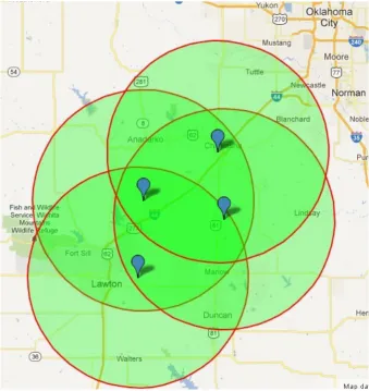
CASA has deployed a networked X-band radar test bed, named Integrated Project 1 (IP1), in southwestern Oklahoma. The IP1 test bed is the first DCAS system of this kind de-veloped and operated by CASA, primarily to monitor and respond to severe thunderstorms, heavy rainfall, and severe winds. The test bed covers a 7000 km2region in southwest-ern Oklahoma that receives an average of 4 tornado warnings and 53 thunderstorm warnings per year. The radars are lo-cated under the NEXRAD coverage of the KFDR and KTLX radars, as shown in Fig. 2.
Fig. 2. The layout and location of the IP1 weather radar network. The coverage circles of IP1 radar are in radius of 40 km.
weather radar systems. The system update time can be as fast as 30 s to 1 min due to the implementation of adaptive, coor-dinated sector scanning strategy.
4 Dual polarization quantitative precipitation estimation
Derivation of quantitative rainfall products from radar ob-servations is known as a highly challenging process be-cause of the inherent variability of hydrometeorological pro-cesses as well as the practical challenges of radar measure-ments in the context of rainfall estimation. Cifelli and Chan-drasekar (2010) delineated these issues into two categories: physical science issues and engineering considerations. The microphysical variability can be largely accounted for us-ing dual polarization measurements, such as combinations of the radar reflectivity, the differential reflectivity, and the specific differential propagation phase (Bringi and Chan-drasekar, 2001). Rainfall estimation fromKdpis particularly appealing in X-band radar networks, because (1) it avoids
the uncertainty in attenuation correction; (2) Kdp is sensi-tive to light rainfall at short wavelengths; (3) as the range slope of differential phase, it does not need network cali-bration for the four radar nodes. Deploying the radars as a network addresses the engineering challenges faced in rain-fall estimation such as beam height, resolution and clutter issues, whereas using the Kdp-based product addresses the physical science issues as discussed in Cifelli and Chan-drasekar (2010).
Fundamentally, radar QPE is built upon physical models of the rain medium relating rain microphysics and radar observ-ables (Bringi and Chandrasekar, 2001). TheR−Kdprelation can be expressed in a power law form as
R=aKdpb. (2)
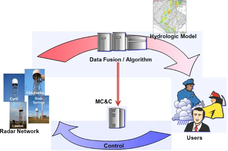
Fig.3. CASA Architecture
4. DUAL POLARIZATION QUANTITATIVE PRECIPITATION ESTIMATION
Derivation of quantitative rainfall products from radar observations is known as a highly
challenging process because of the inherent variability of hydrometeorological processes as
well as the practical challenges of radar measurements in the context of rainfall estimation.
Cifelli and Chandrasekar (2010) delineated these issues into two categories namely, physical
science issues and engineering considerations. The microphysical variability can be largely
accounted for using dual polarization measurements, such as combinations of the radar
reflectivity, the differential reflectivity, and the specific differential propagation phase (Bringi and
Chandrasekar 2001). Rainfall estimation from
K
dpis particularly appealing in X-band radar
networks, because 1) it avoids the uncertainty in attenuation correction; 2)
K
dpis sensitivity to
light rainfall at short wavelengths; 3) as the range slope of differential phase, it does not need
network calibration for the four radar nodes. Deploying the radars as a network, addresses the
engineering challenges faced in rainfall estimation such as beam height, resolution and clutter
Fig. 3. CASA Architecture.is small, and therefore it has to measure as the slope of8dp. However, by going to higher frequencies, theKdp threshold is smaller and henceR(Kdp)can be used for light rain. The estimation ofKdpis a challenge as the range derivative of the differential propagation phase profiles. It is subject to sub-stantial fluctuations, especially at low rain rates, that need to be suppressed with a filter. However, the filter will smooth out the peaks on the other hand and introduce biases at high rain rates (Gorgucci et al., 1999). An adaptiveKdpalgorithm automatically tuned to the spatial gradient ofKdpwas imple-mented in the CASA QPE system that substantially reduces the fluctuation in light rain and the bias in heavy rain (Wang and Chandrasekar 2009). Figure 4a shows a snapshot ofKdp estimates for each IP1 radar. It can be seen that theKdpfield is fairly stable in the low rain rate regions and is high in the storm cores.
The IP1 QPE test bed was designed with overlapping cov-erage among its radar nodes. The independence ofKdp on the radar calibration enables flexibility in combining the col-locatedKdpestimates from all the radar nodes. It is theKdp field, rather than the rainfall field, to be merged because we want to further reduce the variation on the input to the nonlin-earR−Kdpconversion. The compositeKdpfield comes from the radar with lowest beam height and nearest slant range, or from the radar with the best Kdp estimates. Moreover, the data availability is further enhanced by the overlapped topol-ogy in cases of heavy rainfall, or blockage or any other factor requiring redundancy demonstrating the operational strength of the network centric system.
(a)
(b)
Fig.4. Composite Kdp estimates from the IP1 radar network, on 08:12 UTC, May 27, 2008. (a)
the estimated Kdp field for each IP1 radar (b) the merged Kdp field based on the data quality of
Kdp.
5. The QPE system functions and cross validation
Fig. 4. CompositeKdp estimates from the IP1 radar network, on
08:12 UTC, 27 May 2008. (a) the estimatedKdpfield for each IP1
radar, (b) the mergedKdpfield based on the data quality ofKdp.
5 The QPE system functions and cross validation 5.1 QPE System functions
The IP1 network is operated over a set of dynamic scan strategies where new scan protocols are continuously being developed and evaluated to serve the needs of a diverse end-user base, as shown in the architecture in Fig. 3. The net-work centric sensing can be implemented at varying time and spatial scales. The data flow architecture of QPE system is shown in Fig. 5a, demonstrating the data flow, whereas the functional system diagram for QPE product interface with end-users is shown in Fig. 5b. The high-resolution hydro-logic model is eventually integrated into a DCAS network. As an end-to-end system, multiple aspects of flood forecast-ing prevention will be investigated, includforecast-ing data fusion,
(a)
(b)
Fig.5. (a) Data Flow for QPE (b) Functional Architecture of urban floods monitoring system integrated into a DCAS radar network.
In the QPE system, the Kdp estimates are produced on a node basis. This can be done
physically either at the node level or at the central facility. The rainfall product generation
happens at the central facility. There are several background processes that happen between
the Kdp generation and rainfall estimation. Some of them include “data fusion” of rainfall
estimation from multiple radar nodes. The governing principles for the QPE data fusion, just
based on the radar nodes was described in section 4. This is the module that will be expended if
external auxiliary data was brought in such as a radar outside the network, or real time
adjustment with in-situ sensors. One of the key processes, in the central facility is the
conversion of products from the radar coordinate system to the common geophysical coordinate
system. Nearly all of the conventional radar products are generated with the radar as the origin. Fig. 5. (a) Data flow for QPE, (b) functional architecture of urban
floods monitoring system integrated into a DCAS radar network.
rainfall estimation, short-term precipitation forecast, and user impact. The interaction between flood warnings and people response will also be investigated, in order to deliver better risk information to the users with different requirements. In addition to the standard QPE systems, an additional subsys-tem for nowcasting is also implemented in the QPE syssubsys-tem (Ruzanski et al., 2011). This system has undergone extensive evaluation including the interface of QPE subsystem within the nowcasting system (Ruzanski and Chandrasekar, 2011).
2818 V. Chandrasekar et al.: The CASA quantitative precipitation estimation system
with in-situ sensors. One of the key processes in the cen-tral facility is the conversion of products from the radar co-ordinate system to the common geophysical coco-ordinate sys-tem. Nearly all of the conventional radar products are gen-erated with the radar as the origin. However, with more than one radar in the system, such a convention is not possible. The various products including the QPE, along with other products such as composite radar reflectivity factor, multiple-Doppler wind velocity vectors, and nowcast products are pro-duced in standard geophysical reference coordinates such as lat/long , Google Maps and GIS interface system that are used by the end-user community. In addition, these prod-ucts are also delivered in a user-defined software environ-ment such as, “Weather Scope”, used by the Norman local emergency manager community, and WDSS II system, used by the local forecast community. There are special products that can be produced in addition to the standard rainfall maps (Surface Rainfall Intensity product), namely the hourly ac-cumulation maps and single location rainfall acac-cumulation trace, which can be used to compare against rain gauges.
5.2 Cross validation
CASA has conducted extensive validation studies on radar rainfall estimation using X-band dual-polarization radar. The metrics of validation include the mean bias, the normalized mean bias and the normalized standard error, defined respec-tively as follows:
< e >= hRR−RGi (3)
< e >N=
hRR−RGi
hRGi (4)
NSE=h|RR−RG|i hRGi
(5) where brackets denote sample average, RR is the radar es-timate, andRG is the gauge measurement of instantaneous rainfall rate or hourly rainfall accumulation.
Since 2007, several intensive operation (IOP) experiments have been conducted in IP1, mostly during the spring storm season, to demonstrate and evaluate the fundamental concept of DCAS system and investigate the value added impact of this networked weather radar system compared to conven-tional weather radar systems (Chandrasekar et al., 2008). For use in the radar rainfall algorithm, a wide range of coeffi-cients has been reported for theR−Kdppower law relation (Bringi and Chandrasekar, 2001) at both S-band and X-band. For fair comparison, the KOUN’sR−Kdprelation was se-lected, which has been evaluated at S-band for the prototype WSR-88D system (Ryzhkov et al., 2005). The relation was scaled to X-band with respect to wavelength for rainfall con-version in the IP1 test bed, resulting in
R=18.15Kdp0.791 (6)
radar rainfall algorithm, a wide range of coefficients has been reported for the
R-K
dppower law
relation (Bringi and Chandrasekar, 2001) at both S-band and X-band. For fair comparison, the
KOUN’s
R-K
dprelations was selected, that has been evaluated at S-band for the prototype
WSR-88D system (Ryzhkov et al. 2005). The relation was scaled to X-band with respect to
wavelength for rainfall conversion in the IP1 test bed, resulted as
791 . 0
15
.
18
K
dpR
(6)
The performance of the IP1 QPE product was evaluated for all major rain events against the
USDA Agriculture Research Service’s gauge network (MicroNet) in the Little Washita
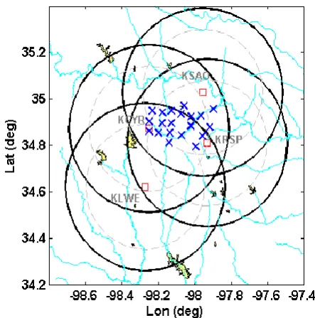
watershed, which comprises 20 weather stations in the center of the test bed as shown in Fig.6.
Fig. 6 Location of the USDA ground gauges in the CASA’s IP1 network.
In total, 42 storm events from the CASA experiments are analyzed in this paper, including
events of different storm types such as severe thunde
rstorm
, convective line, wide spread
stratiform rain, and cold front system. Overall the hourly rainfall estimates compared to the
gauge measurements have a very small bias of 3.74 % and a normalized standard error of 25%.
These aggregate numbers show the excellent performance of the CASA QPE system over a
5-Fig. 6. Location of the USDA ground gauges in the CASA’s IP1network.
The performance of the IP1 QPE product was evaluated for all major rain events against the USDA Agriculture Research Service’s gauge network (MicroNet) in the Little Washita watershed, which comprises 20 weather stations in the center of the test bed (as shown in Fig. 6).
In total, 42 storm events from the CASA experiments are analyzed in this paper, including events of different storm types such as severe thunderstorm, convective line, widespread stratiform rain, and cold front system. Overall, the hourly rainfall estimates compared to the gauge measure-ments have a very small bias of 3.74 % and a normalized standard error of 25 %. These aggregate numbers show the excellent performance of the CASA QPE system over a 5-yr time period. The performance is also about a factor of three improvements over the current long-range weather radar es-timates of rainfall reported in the literature.
6 Sample products from the CASA QPE system
Fig. 7a. Instantaneous rainfall map.
adjusted to match the response scale of the basin of interest. For the IP-1 test bed, this time was set at 60 min.
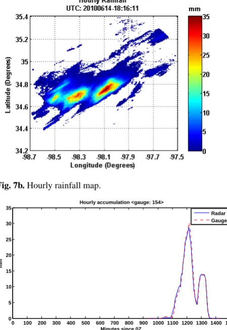
The following shows examples of instantaneous rainfall maps and hourly rainfall accumulation maps at the test bed, for 14 June 2010 case. Figure 7a shows a sample of instanta-neous rainfall maps over a storm event, and the Fig. 7b shows the hourly accumulation maps. In addition, point-wise traces are used for diagnostic purposes for comparison against gauges, and a detailed comparison against gauges at some of the Little Washita gauge network locations is shown in Fig. 7c for this rainfall event (at gauge number 154 location: Lat: 34.8553, Long:−98.1369). It can be clearly seen that the QPE system in CASA produces stable products for use in downstream applications such as flood forecast and input to hydrologic models. In addition to the standard QPE prod-ucts, these products are also being tested with additional sub-systems such as nowcasting. The current nowcasting product produces future time forecasts of reflectivity maps at fixed lead times – namely 5 min to half an hour. However, experi-mental products are being developed to produce nowcasting products of rainfall maps directly and they are under eval-uation (Ruzanski and Chandrasekar, 2011). The preliminary results of Ruzanski and Chandrasekar (2011) show that the performance of direct QPE nowcasting is superior to going through the route of reflectivity and converting to rainfall.
7 Summary and conclusions
This paper described the CASA QPE system, the archi-tecture, and its performance. This paper also described the process of high-resolution quantitative precipitation estima-tion (QPE) from a X-band dual-polarizaestima-tion radar network, which is expected to improve flood warning. High spatiotem-poral resolution is also one of the essential requirements for prevention of flash floods and urban floods. Urban devel-opment reduces the response time of urban watersheds to rainfall and increases the peak discharge volumes. Equipped
Fig. 7b. Hourly rainfall map.
0 100 200 300 400 500 600 700 800 900 1000 1100 1200 1300 1400 1500 0
5 10 15 20 25 30 35
Minutes since 0Z
mm
Hourly accumulation <gauge: 154>
Radar Gauge
Fig. 7c. Radar and gauge hourly rainfall comparison at the location
of gauge 154 for 14 June 2010 event.
with high-resolution rainfall maps, physically based dis-tributed hydrologic models have significant advantage for accurate monitoring of urban watersheds and drainage net-works.
infrastructure to support the conventional long-range radar system is a major task in an urban environment, due to the social footprint of such systems. This is one of the major mo-tivations driving the deployment of small-size X-band radars. The QPE validation studies over 5 yr have shown very good match between radar QPE and ground-based rain gauge network measurements, compared to the current state of the art. The excellent performance also shows the advantage of the network concept. The same studies also demonstrated the operational feasibility using X-band dual-polarization radar for accurate rainfall mapping and, in combination with the high resolution, the potential for driving the urban floods warning systems. Two types of products (namely instan-taneous rainfall maps and rainfall accumulation maps) are shown to demonstrate the types of output products. In ad-dition, point-wise trace of rainfall accumulation is used for validating against rain gauge networks. The interaction of the QPE subsystem with the nowcasting subsystem shows the potential for rainfall nowcasting.
Acknowledgements. This research is supported by the National
Science Foundation via the NSF/Engineering Research Center Program ERC-0313747.
Edited by: N. Rebora
Reviewed by: H. Pohjola and one anonymous referee
References
Bringi, V. N. and Chandrasekar, V.: Polarimetric Doppler Weather Radar: Principles and applications, Cambridge University Press, 648 pp., 2001.
Bharadwaj, N., Chandrasekar, V., and Junyent, F.: Signal Process-ing System for the CASA Integrated Project I Radars, J. Atmos. Ocean. Technol., 27, 1440–1460, 2010.
Chandrasekar, V., McLaughlin, D. J., Brotzge, J., Zink, M., Philips, B., and Wang, Y.: Distributed Collaborative Adaptive Radar Net-work: Preliminary Results from the CASA IP1 Testbed, 2008 IEEE Radar Conference, Rome, Italy, 2008.
Chandrasekar, V., Willie, D., Wang, Y., Lim, S., and McLaughlin, D.: Attenuation margin requirements in a networked radar sys-tem for observation of precipitation, IEEE Int. Geoscience and Remote Sensing Symp., IGARSS 2009, 2, Cape Town, South Africa, IEEE, 957–959, 2009.
Cifelli, R., and Chandrasekar, V.: Dual polarization radar rainfall estimation. Rainfall: State of the Science, edited by: Testik, F. Y. and Gebremichael, M., Geophys. Monogr. Ser., 191, 105–125, AGU, Washington, DC, 2010.
Gorgucci, E., Scarchilli, G., and Chandrasekar, V.: Specific Differ-ential Phase Estimation in the Presence of Nonuniform Rainfall Medium along the Path, J. Atmos. Ocean. Technol., 16, 1690– 1697, 1999.
Junyent, F. and Chandrasekar, V.: Theory and characterization of weather radar networks, J. Atmos. Ocean. Technol., 26, 474–491, 2009.
Junyent, F., Chandrasekar, V., McLaughlin, D., Insanic, E., and Bharadwaj, N.: The CASA Integrated Project 1 Networked Radar System, J. Atmos. Ocean. Technol., 27, 61–78, 2010.
Maki, M., Maesaka, T., Misumi, R., Iwanami, K., Suzuki, S., Kato, A., Shimizu, S., Kieda, K., Yamada, T., Hirano, H., Kobayashi, F., Masuda, A., Moriya, T., Suzuki, Y., Takahori, A., Lee, D., Kim, D., Chandrasekar, V., and Wang, Y.: X-band Polarimetric Radar Network in the Tokyo Metropolitan Area – X-NET, The fifth European Conf. Radar Meteor. Hydrology, Helsinki, Fin-land, ERAD, 3.7., http://erad2008.fmi.fi/proceedings/extended/ erad2008-0020-extended.pdf., 2008.
McLaughlin, D. J., Chandrasekar, V., Droegemeier, K., Frasier, S., Kurose, J., Junyent, F., Philips, B., Cruz-Pol, S., and Colom, J.: Distributed Collaborative Adaptive Sensing (DCAS) for Im-proved Detection, Understanding, and Prediction of Atmospheric Hazards, 9th Symp. Integrated Obs. Assim. Systems, Amer. Me-teor. Soc., 2005.
NRC: National Research Council: Flash Flood Forecasting Over Complex Terrain: With an Assessment of the Sulphur Moun-tain NEXRAD in Southern California, National Academy Press, 2005.
NRC: National Research Council: Observing Weather and Climate from the Ground Up: A Nationwide Network of Networks, Na-tional Academy Press, 2008.
Ruzanski, E. and Chandrasekar, V.: Scale filtering for improved nowcasting performance in a high-resolution X-band radar net-work IEEE Trans. Geosci. Remote Sens., 49, 2296–2307, 2011. Ruzanski, E., Chandrasekar, V., and Wang, Y.: The CASA
Nowcast-ing System, J. Atmos. Ocean. Technol., 28, 640–655, 2011. Ryzhkov, A. V., Giangrande, S. E., and Schuur, T. J.: Rainfall
Es-timation with a Polarimetric Prototype of WSR-88D., J. Appl. Meteor., 44, 502–515, 2005.
Ryzhkov, A. V.: The Impact of Beam Broadening on the Quality of Radar Polarimetric Data., J. Atmos. Ocean. Technol., 24, 729– 744, 2007.
Saltikoff, E., Huuskonen, A., Hohti, H., Jarvinen, H., and Koistinen, J. : Quality assurance in the FMI Doppler weather radar network, Boreal Environ. Res., 15, 579–594, 2010.
Siggia, A. D. and Passarelli, R. E.: Gaussian model adaptive pro-cessing (GMAP) for improved ground clutter cancellation and moment calculation, Proc. of 3rd European Conf. on Radar in Meteorol. and Hydrology (CDROM), Visby, Sweden, 2004. Wang, Y. and Chandrasekar, V.: Algorithm for Estimation of the
Specific Differential Phase, J. Atmos. Ocean. Technol., 26, 2565–2578, 2009.
Yoshikawa, E., Ushio, T., Kawasaki, Z., Mega, T., Yoshida, S., Mo-rimoto, T., Imai, K., and Nagayama, S.: Development and initial observation of high-resolution volume-scanning radar for mete-orological application, IEEE Trans. Geosci. Remote Sens., 48, 3225–3235, 2010.
Zhang, J. and Qi, Y. : A Real-Time Algorithm for the Correction of Brightband Effects in Radar-Derived QPE, J. Hydrometeor., 11, 1157–1171, 2010.