http://www.sciencepublishinggroup.com/j/ijmea doi: 10.11648/j.ijmea.20180606.12
ISSN: 2330-023X (Print); ISSN: 2330-0248 (Online)
Solidification and Filling Related Defects Analysis Using
Casting Simulation Technique with Experimental Validation
Nazma Sultana, Md. Rafiquzzaman, Younosur Rahman, Apurba Das
*Department of Industrial Engineering and Management, Khulna University of Engineering & Technology (KUET), Khulna, Bangladesh
Email address:
*
Corresponding author
To cite this article:
Nazma Sultana, Md. Rafiquzzaman, Younosur Rahman, Apurba Das. Solidification and Filling Related Defects Analysis Using Casting Simulation Technique with Experimental Validation. International Journal of Mechanical Engineering and Applications.
Vol. 6, No. 6, 2018, pp. 150-160. doi: 10.11648/j.ijmea.20180606.12
Received: September 13, 2018; Accepted: November 2, 2018; Published: January 28, 2019
Abstract:
Solidification as well as filling has great influences on the quality of cast products. In modern competitive world for increasing the quality of products these two steps draw higher attention to casting engineers. This case study is just one of the followings of the above mentioned objective. The aim of the present work is to reduce the rejection rate of cast products in a foundry shop due to casting defects in sand casting process using a computer aided simulation technique. In general conventional techniques require a larger number of trials with higher costs for checking outputs when the number of process parameters increase that can be reduced using simulation. For the simplification in this analysis grain size of sand, material quality, casting process parameters are considered uniform for all cases. Only the positional and dimensional variances are taken in considerations for defects analysis. It is found that defects such as shrinkage porosity, improper solidification, air entrapment, mould erosion are directly related with gating and feeding system design and although other process parameters are considered uniform but this defects will be changed with changing the design parameters. In this case Click2cast casting simulation software is used for mould filling and solidification analysis and it is observed that proposed gating and feeding system design improves casting yield approximately 15% more than conventional gating and feeding system. The validation of simulation is proved through experimental trials in foundry shop.Keywords:
Shrinkage Porosity, Improper Solidification, Air Entrapment, Mould Erosion, Click2cast1. Introduction and Literature Review
Sand casting is one of the versatile methods of metal shaping because it is used most frequently for intricate shape casting practically both of ferrous or nonferrous material. Further, the necessary tools required for sand casting are very simple and inexpensive. For this reason it is an ideal method for trial production or production of a small lot. It consists of pouring molten metal into a sand mould cavity, allowing the metal to solidify and then breaking away the mould for getting the cast product. However the surface finish and dimensional accuracy achieved by normal sand casting process are not adequate for final output in many cases, therefore many improvements can be done through quite modifications of casting process. Green sand casting process parameters perform a vital role for enhancing the quality of cast products. Many researchers performed their research on optimizing the
value of casting process parameters to improve the quality of cast products using various techniques over the past few years [1-24]. Up to now following methods are used for process design: Design of Experiments (DoE) techniques such as Taguchi approach, Response Surface Methodology (RSM), integrated approach of Taguchi approach and Response Surface Methodology (RSM), Finite Element Analysis (FEA), casting simulation techniques such as Magma 5, Quick cast, Auto Cast X, Solid cast simulation software’s, Artificial Neural Network (ANN), Gradient Search method [1-2].
gating and feeding system to obtain defect free casting. The main function of gating system is to carry clean molten metal from ladle to the casting cavity ensuring complete filling. For a given casting geometry an optimized gating design satisfying the entire requirement is obtained by experimentation through trial and error methods. But this technique takes a long time to get the desired dimensions of the gating channels and also increases cost to the company. This problem can be solved easily by using simulation that represents the actual mould filling and solidification process, so that we can predict the results in advance before producing actual casting. Research work published on optimization of gating system recommends maximizing the casting yield, minimizing the in-gate velocity of molten metal, ensuring directional solidification, optimizing the in-gate and riser location.
In this research the contributions of various researchers on casting simulation techniques for various gating and feeding system design in reducing casting defects in variety of cast parts are also studied. Gating design has a great impact on mould filling for light metal casting processes and the author provided validation of this statement through experimentation [3]. The suggestion of the authors is that optimization method assists in reducing casting related defects. The proper location, size and design of gating and feeder system improved the shrinkage porosity and cracks in cast products [4].
The authors described that proper dimension and positioning of riser and in-gates is very important in casting processes and they performed simulation for casting gear box of automobile components with the help of Auto-CAST software. They concluded that simulation of filling and gating system reduced the casting defects of cast iron in foundries [5]. One of the critical elements that has to be considered for producing a high quality sand casting product is the gating and risering system design [6-7]. Improper design of gating and risering system results in cold shut and shrinkage porosities. These defects negatively affect mechanical properties. Therefore adequate care is necessary in designing gating and risering systems for improved yield of defect free castings [8]. It has been shown that good gating system design could reduce the turbulence of melt flow, air entrapment, sand inclusion, oxide film and dross [9-14]. Melt flow influences solidification time, which is an important parameter that could alter the microstructure and mechanical properties of the cast part. This parameter is influenced by design and dimension of gating components and also impart on the cooling rate of the casting. Metal head height/pressure head/metal head is a vital gating component; it is the vertical distance between the metal pouring height and the top surface of the casting or simply the height of the metal in the sprue [15]. Hot spot from casting can be removed through optimum positioning and designing of riser and author has designed riser with higher value of modulus for increasing the solidification time compared to casting [16]. Computer-aided casting design and simulation is a faster tool for optimizing the feeder design of castings [17]. ABAQUS is applied for detection of casting defects during solidification of Aluminium alloy and author has concluded that most of the defects are formed where the metal solidified last [18].
Thermal analysis during mould filling time using FORTRAN has been done and the findings of this research is that the lastly solidifying area is near the junction [19-20]. The application of computer aided method, and casting simulation in foundries can reduce the bottleneck operations and excess non value added time in casting development, the number of required trial casting are reduced for simulation on the shop floor [21].
The authors applied AutoCAST-X1 simulation software for analysing this defects for wear plate mass production. They described that vertical gating and feeding system is not suitable for thick cast metal. They proposed horizontal gating and feeding system in this case and in their experiments 30% defects are reduced [22]. For reducing the shrinkage at the joint between the axle head and the main body of the impellor of 200ZJA slurry pump was reduced only reducing the distance from risers to axle head without changing the number or the design of gating system using ProCAST software [23]. The authors observed that solidification simulation using Vector Gradient Method (VGM) enables visualization of the progress of freezing inside a casting and identification of the last freezing regions or hot spots. Hence, an exothermic sleeve was attached to the feeder, which has completely shifted the hot spot in the feeder and there by eliminated shrinkage defect problem. This facilitated the optimized placement and design of feeders with improvement in yield by 20% while ensuring casting soundness without expensive and time-consuming trial runs [24].
From the above literature review it can be concluded that simulation technique helps to reduce filling and solidification related casting defects. But the gating and feeding system design for multi-cavity mould are performed a very few using simulation techniques. In this research casting related defects are tried to reduce for multi-cavity mould using simulation. This study has been carried out in following stages, viz. studying the way of designing various parts of feeder and gating system, comparative analysis of the conventional and newly designed gating systems based on simulation results using Click2cast simulation software, finding out the casting yield (%) for both cases from simulation results, experimental validation with simulation results through job shop trials for new design.
2. Simulation Technique for Casting
Defects Analysis
Figure 1. Sequential procedures of Click2Cast simulation technique for casting defects analysis
3. Solidification and Filling Related
Defects Analysis Using Casting
Simulation Technique
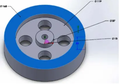
In this section multi cavity sand mould is used. As per the foundry requirement, Aluminium (AlSi7Mg) is used as a casting material and green sand is selected as mould material. The specifications of the cast parts are 165 mm diameter, 32 mm height with a centre hole of 13 mm diameter, and four holes surrounding the centre is shown in figure 2. Wooden pattern is used for getting good quality of mould cavity and casting and it is easily available at a cheap rate.
Figure 2. Specification of cast part (all dimensions are in mm).
3.1. Conventional Design of Gating and Feeding System for Manufacturing Flywheel in Our Foundry Shop
Studying the conventional design of gating and feeding system of multi-cavity mould is one of the prerequisite steps of proposing a new design of gating system for minimizing casting defects. For fulfilling this requirement the existing gating design for aluminium flywheel manufacturing in foundry shop of Khulna University of Engineering & Technology was selected. The first observation was that, in the conventional process no theoretical calculations are applied. The horizontal top gate and riser are used for filling of molten metal into the cavity with no runner extension. Riser is placed on the top centre of the plate as well as the height and diameter of riser is 76.2mm and 13mm sequentially. The other dimensions of sprue, runner, and in-gate are shown in table 1. In table the symbols that are used contains the following meanings: D=Diameter, W=Width, H=Height.
Table 1. Dimensions of conventional gating and feeding system.
Type Sprue (mm) Sprue base well (mm) Runner(mm) Riser(mm) In-gates(mm)
D(base) D(top) H D H W L H D H W L H
Conventional gating
and feeding system 12.7 25.4 76.2 25.4 16 25.4 50.8 8 13 76.2 - - -
3.2. Designing and Positioning of Elements of Proposed Gating and Feeding System
In this step a new design of gating system is proposed. For attaining the goal of our research, proper dimensioning and positioning of sprue, runner, riser and in-gates are determined based on various established mathematical calculations. Any Casting design mainly consists of three basic designs: pattern design, gating system design and finally the feeder/riser design. Pattern allowances are provided in casting processes for compensating dimensional and structural inaccuracies. The molten metal flows from the sprue to cavity through runner and in-gates. So the proper dimensions and positioning of sprue, runner and in-gates have a great influence on casting defects. Gating ratio for Aluminium, sprue (1): runner (2): in-gates (1) [26].
Element 1: Proposed pouring basin
It is not a wise decision to pour molten metal directly into the mould cavity because it may cause mould erosion. The
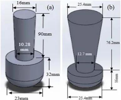
Figure 3. 3D view of (a) conventional and (b) proposed pouring basin (all dimensions are given in mm unit)
Element 2: Proposed Sprue and sprue base well
The passage which connects the pouring basin to the runner or in-gate is called sprue. It is generally designed taper shaped in downward to avoid aspiration of air in sand casting because straight cylindrical shape creates a low pressure area around the metal of the sprue. The exact tapering dimension and choke area are measured using equation 1 and 2 [26]. Sprue base well is a reservoir for metal at the bottom of the sprue which reduces the mould erosion through reducing the momentum of flow metal. Generally the well diameter for one runner system is twice the width of a runner. In this research efficiency factor C=0.9 is assumed because of single runner tapered sprue [25]. 3D view of sprue with sprue base well is represented in Figure 4.
Figure 4. 3D view of (a) conventional and (b) proposed sprue with sprue base well.
For tapered dimensions,
(1)
Choke Area,
A mm2Sprue area 2 choke area (2)
Here the significant meaning of symbols are given:
At Area of sprue(top)
Ac Area of choke
ht Height of sprue(top)
hc Height of choke
t Pouring time
d Mass density molten metal
g Acceleration due to gravity
H Effective sprue height
C Efficiency factor, 0.90
w Mass of metal poured into the mould
Element 3: Proposed Runner with its extension
It is generally located in the horizontal plane (parting plane) which connects the sprue to its in-gates. The main considerations of runner design is its dimension because if the size of in-gates is larger than runner then uniform flow will be disturbed and runner extension is provided in this design because it helps to trap the slag of molten metal. The area of runner is determined using equation 3 [26].
Area of runner 2 sprue area (3)
Element 4: Proposed In-gates
The connection between runner and mould cavity is maintained through this small passage. The cross section of gates may be square, rectangular and trapezoidal. The in-gates are generally made wider compared to depth. In this study two partial in-gates with same dimensions are provided. Pressurized gating system with gating ratio 1(sprue):2(runner):1(in-gate) is used in this analysis [26].
Element 5: Proposed Riser and its positioning
Shrinkage is a very normal nature of molten metal during solidification. The function of a riser is to feed the casting during solidification so that no shrinkage cavities are formed. For that reason it is also named feeder. In this analysis the optimum riser size is determined using Modulus method. Two centre risers are used for this casting which provides directional solidification and the dimensions are calculated using following formula 4 [26].
Diameter of Riser, Dr= 6Mc Mc = Modulus of casting D= Diameter of casting H= Height of casting Modulus of casting,
M $#% &# (4)
Using the above mathematical equations, dimensions for gating and feeding components are derived which are shown in table 2.
Table 2. Dimensions of proposed gating and feeding system (D=Diameter, H=Height, L=Length, W=Width).
Type Sprue (mm) Sprue base well (mm) Runner(mm) Riser(mm) In-gates(mm)
D(base) D(top) H D H W L H D H W L H
Casting Yield:
The casting yield is the proportion of the actual casting mass to the mass of metal poured into the mould expressed as a percentage in equation 5 [25].
Casting yield . 100% (5)
Here, W= actual casting mass, w= mass of metal poured into the mould
3.3. Comparative Analysis of Conventional and Proposed Gating and Feeding System with Simulation and Experimental Results
This section highlights the application of Click2cast software for analysing casting defects during filling and
solidification of molten metal.
Step 1: PART Module creation
The prerequisite of this software is to create the part model in CAD software and save it as a standard STL format for importing in Click2cast. The simulation is carried out for AlSi7Mg Green sand casting process. Process parameters such as the melting point of aluminium 713°C, green sand temperature 20°C, and gravity flow of molten metal are selected for simulation. Figure 5 represents drawing model of conventional and optimized gating and feeding system. The casting is automatically meshed into cubic elements for internal computations such as thickness, solidification and mould filling. The mesh size is defined as 2 mm.
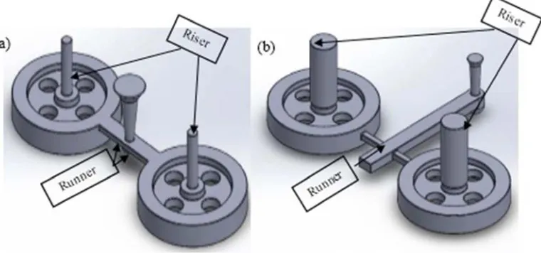
Figure 5. CAD models of (a) conventional and (c) proposed gating and feeding design.
Step 2: Filling process analysis results
Filling process is simulated to view the flow of molten metal through the gating system and to predict the filling related defects such as air entrapment, mould erosion etc. This helps in verifying the optimal gating system. Air entrapment into cast element helps to produce blow holes. In
Figure 6. Air entrapment result of (a) conventional and (b) proposed gating and feeding design.
Mould erosion is also analysed in this step. The main reason of occurring mould erosion is high velocity of flowing molten metal into the cavity. From simulation results it is found that in conventional gating system the maximum velocity of liquid flow from sprue to runner is 403.74 m/s but in modified gating design provides only 152.58 m/s velocity
and in this design the molten metal cannot enter the cavity directly from runner so the entering velocity is much more lower than conventional design. Mould erosion is almost disappeared in proposed gating system but in conventional gating design percentage of mould erosion is appeared in larger regions of cast product which is viewed in figure 7.
Step 3: Solidification analysis results
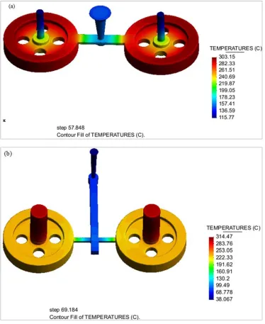
Casting solidification in figure 8 helps to view the cooling process from exterior casting surface to interior, and to detect the location of shrinkage porosity. This analysis helps to optimize and verify the design of risers, so that the casting yield is improved with desired quality. Here, two main results
are achieved: one is directional solidification (thin regions solidify faster than thick regions) and another is progressive solidification meant casting surface to interior. Equal temperature distribution throughout the cast body is an indication of progressive solidification.
Figure 8. Casting solidification of (a) conventional and (b) proposed gating and feeding design.
From the figure 8, it is noticed that both progressive and directional solidification is achieved in modified gating and feeding system design. From temperature scale it is clearly shown that yellow colour represents low temperature and red colour indicates high temperature. In conventional gating and feeding system riser is solidified before the solidification of
Figure 9. Shrinkage porosity of (a) conventional and (b) proposed gating and feeding design.
Step 4: Experimental Trial casting in proposed gating system
The first step of experimental trial is to prepare a wooden
Figure 10. Components of proposed gating and feeding system with multi-cavity mould.
Table 3. Casting yield for conventional and proposed gating system design.
Iteration No. Conventional gating system Proposed gating system
Casting yield (%) 39 45
Bentonite is used as a binding material that increases the mould strength. The mould cavity consists of two parts, cope (20×12×6) inch - the upper part and drag (20×12×3) inch - the lower part. After preparing mould box molten Aluminium is removed from furnace at 713°C and poured into mould
cavity. After 1 hour passing the cast product is collected from moulding box. Sand, dust are washed out using water and then excess metal, gates, runner and risers are cut off from cast product. At last the final product is found which is represented in figure 11.
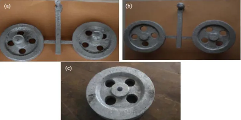
Figure 11. (a) Top view and (b) bottom view of multi-cavity mould aluminium flywheel with proposed gating elements (c) Cast flywheel after removing gating elements and cleaning dust.
Finally casting yield is determined using equation 5 for both gating system cast product that are represented in table 3 and casting yield is increased 15% more than conventional
gating design. Casting yield (%) calculations for new gating design is illustrated below.
Total volume of flywheel
53.144 ∗ 165 ∗ 165 ∗ 32< = 54 ∗3.144 ∗ 27 ∗ 27 ∗ 13< = $3.144 ∗ 119 ∗ 119 ∗ 19 @ 53.144 ∗ 37 ∗ 37 ∗ 26< = $3.144 ∗ 13 ∗ 13 ∗ 32& 466856 BB3
Mass of multi = cavity casting
2 ∗ 466856 ∗ 0.00000265 2.5 CD Mass of metal poured
2.5
0.45 5.6CD After casting the mass of flywheel=2.5kg
Maximum pouring rate 0.3CDF
Pouring time 5.60.3 18.67F
Casting yield 2.55.6 45%
4. Conclusions
Simulation technique is used in this study to determine the optimal size and positioning of gating and feeding systems for minimizing the defects. The findings are (a) the optimum size of the gating elements in pressurized parting gating system are: sprue (Dbase=10.28mm, Dtop=16mm, H=90mm), runner (W=18mm, L=200mm, H=16mm), in-gate (W=10mm, L=40mm, H=8mm), riser (D=40mm, H=100mm). (b) Filling results: Modified gating system helps to reduce mold erosion. Air entrapment is replaced from cast product to riser. (c) From solidification results it is found that directional solidification is achieved through changing the size and positioning of gating elements. Shrinkage porosity of cast product is almost removed in newly designed gating system. (d) Simulation results is found to be a good agreement with experimental results and casting yield is found 45% in modified gating system. So it can be declared that system is improved. It can be concluded that simulation helps to visualize filling and solidification phenomena with no wastage of time, energy, labour and money. Hence casting simulation enables to provide ‘correct at the first time’ through preventing potential problems related to flow of metals or during the time of freezing compatible with both product requirements and foundry capability.
References
[1] Johnston, R. E. (1989). Design of experiments: Taguchi in the foundry. Transactions of the American Foundrymen's Society, 97, 415-418.
[2] Kumar, P., &Gaindhar, J. L. (1995). Off‐line quality control for V ‐process castings. Quality and reliability engineering international, 11(3), 175-181.
[3] Masoumi, M., Hu, H., Hedjazi, J., &Boutorabi, M. (2005). Effect of gating design on mold filling. Transactions of the American Foundry Society, 113, 185-196.
[4] Choudhari, C. M., Padalkar, K. J., Dhumal, K. K., Narkhede, B. E., & Mahajan, S. K. (2013). Defect free casting by using simulation software. In Applied Mechanics and Materials, 313, 1130-1134. Trans Tech Publications.
[5] Bhatt, H., Barot, R., Bhatt, K., Beravala, H., & Shah, J. (2014). Design optimization of feeding system and solidification simulation for cast iron. Procedia Technology, 14, 357-364. [6] Lee, P. D., Chirazi, A., & See, D. (2001). Modelling micro
porosity in aluminium–silicon alloys: a review. Journal of light metals, 1(1), 15-30.
[7] Katzarov, I. H. (2003). Finite element modeling of the porosity
formation in castings. International Journal of Heat and Mass Transfer, 46(9), 1545-1552.
[8] ManjunathSwamy, H. M., Nataraj, J. R., & Prasad, C. S. (2012). Design Optimization of Gating System by Fluid Flow and Solidification Simulation for Front Axle Housing, International Journal of Engineering Research and Development, 4(6), 83-88. [9] Shafiee, M., Rizuan, M., Hashim, M. Y., & Said, M. N. Effects of
gating design on the mechanical strength of thin section castings,
Proceedings of (MUCEET2009) Malaysian Technical Universities Conference on Engineering and Technology June 20-22, MS Garden, Kuantan, Pahang, Malaysia.
[10] Hu, B. H., Tong, K. K., Niu, X. P., and Pinwill, I. (2000), Design and optimization of runner and gating systems for the die casting of thin-walled magnesium telecommunication parts through numerical simulation, Journal of Materials Processing Technology, 105,128-133.
[11] Dai, X., Yang, X., Campbell, J., & Wood, J. (2003). Effects of runner system design on the mechanical strength of Al–7Si– Mg alloy castings. Materials Science and Engineering: A,
354(1-2), 315-325.
[12] Ahmad, R., &Hashim, M. (2011). Effect of vortex runner gating system on the mechanical strength of Al-12Si alloy castings. Archives of Metallurgy and Materials, 56(4), 991-997.
[13] Naveenkumar, B. (2014). S. Kodli,“Design Optimization of Gating System by Fluid Flow and Solidification Simulation for Pump Casing by Sand Casting”. IJREAT International Journal of Research in Engineering & Advanced Technology,
2(4).
[14] Hashim, M. Y., Mohd Amin, A., & Vijay, R. R. Effects of runner diameter on the mechanical strength and porosity distribution of thin section castings. In: Regional Conference on Engineering Mathematics, Mechanics, Manufacturing & Architecture (EM3ARC 2007).
[15] Ochulor, E. F., Adeosun, S. O., &Balogun, S. A. (2015). Effect of Gating Sprue Height on Mechanical Properties of Thin Wall Ductile Iron. World Academy of Science, Engineering and Technology, International Journal of Chemical, Molecular, Nuclear, Materials and Metallurgical Engineering, 9(2), 360-367.
[16] Narkhede, B. E., Choudhari, C. M., & Mahajan, S. K. (2014). Modelling and Simulation for Optimum Design and Analysis of Riser in Sand Casting with Experimental Validation. In
Applied Mechanics and Materials, 465, 657-661. Trans Tech Publications..
[17] C. M. Choudhari, B. E. Narkhede and S. K. Mahajan, A hybrid approach for casting process simulation by combining FEM and VEM for defect minimization with experimental validation, during 7-8-9 February, 2014, 62nd Indian Foundry Congress, Ahmedabad, India
[18] Pequet, C., Rappaz, M., &Gremaud, M. (2002). Modelling of micro porosity, macro porosity, and pipe-shrinkage formation during the solidification of alloys using a mushy-zone refinement method: applications to aluminum alloys.
Metallurgical and Materials Transactions A, 33(7), 2095-2106.
[20] Shahria, S., Tariquzzaman, M., Rahman, M. H., Al Amin, M., & Rahman, M. A. (2017). Optimization of Molding Sand Composition for Casting Al Alloy. International Journal of Mechanical Engineering and Applications, 5(3), 155-161. [21] Behera, R., Kayal, S., &Sutradhar, G. (2011). Solidification
behavior and detection of Hotspots in Aluminium Alloy castings: Computer Aided Analysis and experimental validation. International journal of applied engineering research, 1(4).
[22] Nimbulkar, S. L., &Dalu, R. S. (2016). Design optimization of gating and feeding system through simulation technique for sand casting of wear plate. Perspectives in Science, 8, 39-42. [23] Zhi, X., Han, Y., & Yuan, X. (2015). Casting process
optimization for the impellor of 200ZJA slurry pump. The
International Journal of Advanced Manufacturing Technology,
77(9-12), 1703-1710.
[24] Choudhari, C. M., Narkhede, B. E., & Mahajan, S. K. (2014). Methoding and simulation of LM 6 sand casting for defect minimization with its experimental validation. Procedia Engineering, 97, 1145-1154.
[25] Ravi, B. (2008). Casting simulation and optimisation: benefits, bottlenecks and best practices. Indian Foundry Journal, 54(1), 47.