Analysis of Concentric Split Ring
Square Element for Broadband
Reflectarray Antenna
S. H. Yusop1*, N. Misran1, M. T. Islam2, M. Y. Ismail31
Department of Electrical, Electronic and System Engineering
Universiti Kebangsaan Malaysia, 43600 Bangi, Selangor, Malaysia2
Institute of Space Science (ANGKASA),
Universiti Kebangsaan Malaysia, 43600 Bangi, Selangor, Malaysia
3Communication Engineering Department Faculty of Electrical and Electronics Engineering
Universiti Tun Hussein Onn Malaysia, 86400 Batu Pahat, Johor, Malaysia
*Corresponding e-mail : [email protected]
Abstract
An investigation of phase variation and phase range of concentric split ring square element for broadband reflectarray antenna is presented in this paper. This is realized
by exploiting the physical geometry of three element shapes namely square element, concentric ring square element and concentric split ring square element. Modifying the current distribution of basic concentric ring square element, leads to a less steep phase variation and also the bandwidth performance. An analysis of frequency response is described and analysed. The physical interpretation of the elements is also discussed. The proposed antenna element effectively covers two frequency operations (13.44 GHz and 18.36 GHz) in Ku-band range. Bandwidth broadening is achieved by introducing the ring square combination of element and the practical phase range is achievedthrough the use of RF 35 (thickness = 1.524 mm) as the substrate. The new concept of split initiates to a wider bandwidth (up to 67.6 %) for the antenna and can applied to any two frequency operations of Ku-band applications.
1. INTRODUCTION
Microstrip reflectarrays present an
alternative to the conventional parabolic
reflectors [8], [9]. As its name implies, a reflectarray antenna combines some of the best features of reflector and array
antennas. In its basic form, a microstrip
relfectarray consists of a flat array of
microstrip patches or dipoles printed on a thin dielectric substrate. A feed antenna illuminates the array whose individual elements are designed to scatter the incident
field with the proper phase required to
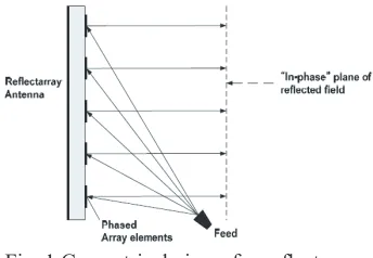
form a planar phase surface in front of the aperture, as shown in Fig. 1. A large
reflectarray antenna is made of thousands antenna elements printed on the flat surface
and illuminated by a feed horn [1], [3].
Fig. 1 Geometrical view of a reflectarray
antenna.
A plane wavefront can be obtained by controlling the scattering properties of each element. The basic design procedure entails
the use of phase-design curves. Various
approaches have been proposed in the past which include the use of variable size patches and identical patches with variable size stubs for obtaining the required phase shift [3], [10].
The key feature of a reflectarray antenna design is the adjustment of the reflected
phase of each of its elements [1], [9]. Microstrip patches of variable size have
been used to control the reflection phase
[10]. This method can be viewed as introducing a small shift in the resonant frequency of an element which in turn
changes the phase of the reflected field.
When a plane wave from a transmitter
reaches the flat reflectarray aperture, the operation of a reflectarray antenna can
be explained as collimating the incident plane wave into the feed horn by suitable phase variations across the surface of the
reflectarray [1].
The microstrip reflectarray has several applications due to its low-profile and
small mass characteristic. One of the
applications is that the flat reflectarray can
be surface-mounted on a building side wall as a Ku-band Direct Broadcast Satellite (DBS) antenna. It also can be mounted on the rooftop of a large vehicle for satellite reception [3].
factor can be solved by reducing the
frequency excursion error by reducing
the N integer in ∆S = (N + d) λ
formula where N is the integer and
d is a fractional number of freespace
wavelength
λ.One of the methods is
to design the reflectarray with a larger
focal-length-to-diameter (f/D) ratio [3].
1. ANTENNA STRUCTURE AND DESIGN
This paper discusses two types of single element namely ring element and square element and two types of concentric element which is the combination of ring and square elements and the combination of split ring and split square ring elements.
Substrate RF-35 is used for all designs with the dielectric constant of 3.54 and the loss tangent of 0.0018 at 1.9 GHz. The unit cell size is 10 mm x 10 mm. CST Microstripes software is used as the tool to analyze the phase variation graph.
2.1. Single ring element behaviour
The conductive ring is a simple
symmetrical element, which can be
nested and optimised for dual frequency
and/or broadband operation [5]. The
resonant behaviour of periodic arrays
of rings is determined by the element
size, periodicity and the electrical
properties of the substrate materials
[7]. In the absence of mutual coupling,
when
λeff = πd(where λeff is the
efficient wavelength and d is the ring
element diameter), the rings resonate
giving 180° reflection phase [7]. The
phase can therefore easily be controlled
by varying the ring element diameter,
and it is this method which is used to
provide the required phase correction
across the reflectarray antenna aperture
[7].
2.2. Single square element design and behaviour
The new proposed element in this paper is a single square element which can give
a better reflection phase range and phase
variation compared to the single ring element.
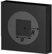
The 3-D geometrical views of the single square element is shown in Fig. 2, where a
is the square length and R is the ring radius from the end edge of the conductor. For investigation of square element structure performance and behaviour, the ratio of the square length and ring radius (a/R) was selected to be 0.7, 0.86, 1 (square length and ring radius is the same), 1.2 and 1.4.
Fig. 2 The 3-D geometrical view of a single
square reflectarray element.
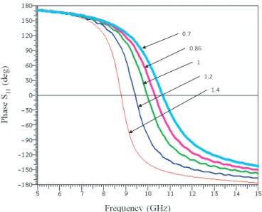
Fig. 3 shows the frequency response for variable-ratio of a/R at the nominal size of ring radius, R = 3.46 mm, the periodicity = 10 mm, the dielectric constant for the
Fig. 3 Frequency response of a single square
reflectarray element with different a/R ratio.
The resonant behaviour of a periodic square element is determined by the element size, periodicity and the electrical properties of the substrate materials. The phase is controlled by varying the square length, a and the ring radius, R. From Fig. 3, it is clearly shown that the phase slope is reduced for the smaller ratio of the square length and the ring radius (a/R). In other words, when R is fixed to one value, the
bandwidth performance is improved for smaller value of square element size, a. However, the linear phase range is also decreased, and therefore, a trade off must be made between these two parameters. In MicroStripes model, 0° phase reflection is used to define the resonance, whereas for a
perfect conductor this is 180° relative to the incident wave.
Fig. 4 shows that a high current density is observed at area x, at the resonant frequency, 9.97 GHz. For a smaller area of copper size x and y, the gradient is improved while the practical phase range is decreased. The element ratio of a/R = 1 therefore is used for further investigation due to the optimum value of the linear phase range and the phasegradient given.
Fig. 4 Surface current distribution at 9.97 GHz
for a grounded square reflectarray element
with a/R ratio = 1. (a = 3.46 mm, R = 3.46 mm,
periodicity = 10 mm, εr = 3.54 and t = 1.524
mm)
2.1. Concentric ring square element design and behaviour
It is shown that the bandwidth of a
reflectarray antenna can be increased by
exploiting the scattering properties of a dual resonant periodic array consisting of nested rings printed on the surface of a grounded dielectric substrate [6]. In common with other types of dual frequency elements, the
Q factor and the linearity of the reflection
phase response can be controlled by varying the inner to outer size ratio. Fig. 5
shows the configuration of concentric ring with square reflectarray element.
In Fig. 5, I is the square ring element radius
and O is the outer ring radius from the first
edge of the conductor to the centre. For concentric ring square element structure, the ratio of the square ring radius and outer ring radius (I/O) was selected to be 0.7, 0.86 and 0.91. Fig. 6 shows the response for the varies ratio of I/O (changing the outer ring radius) at the nominal size of square ring element radius, I = 3.06 mm. The ratio of a/R is kept constant to the value of 1. The periodicity is 10 mm, the dielectric
constant for the substrate, εr is 3.54 and the
Fig. 5 The top-view of concentric ring square
reflectarray element.
Fig. 6 Frequency response of concentric ring
square reflectarray element with different I/O
ratio.
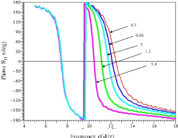
The reflection phase for concentric ring
square element is controlled by varying the outer ring radius, O and the square ring radius, I. From Fig. 6, it is shown that the
first resonant occur depending on the O
dimension whereas the second resonant is similar for all ratios. The phase slope at
first resonance varies for all ratios of the
square ring radius and the outer ring radius (I/O). However, the linear phase range is increased for higher I/O and the plateau region [6] factor is abolished because the
first resonant frequency and the second
resonant frequency are closer. For smaller gap between outer ring and square ring element, performance of phase range is improved.
Fig. 7 shows the frequency response for varies ratio of a/R (changing the square element dimension) with the resonant frequencies at the nominal size of outer ring radius, O = 3.56 mm with I/O = 0.86, periodicity = 10 mm, the dielectric constant
for the substrate, εr = 3.54 and the thickness
of the substrate, t = 1.524 mm. The ratio of square length and ring radius, a/R was selected to be 0.7, 0.86, 1, 1.2 and 1.4.
Fig. 7 Frequency response of concentric ring
square reflectarray element with different a/R
ratio.
From Fig. 7, it is shown that the phase slope and phase range for second resonance is varied for all ratios of a/R. The phase slope is decreased for smaller ratio of a/R , however the linear phase range is decreased and the plateau region is abolished. For smaller size of square element a, the gradient performance for concentric ring square is improved.
It is evident that the outer ring radius
determines the first resonant frequency because the first resonance in Fig. 6 is varied
Fig. 8 Surface current distribution (a) at 7.48 GHz and (b) at 11.78 GHz for a grounded
concentric ring square reflectarray element
with a/R = 1 and I/O = 0.86. (O = 3.56 mm, a = 3.06 mm, R = 3.06 mm, periodicity = 10
mm, εr = 3.54 and t = 1.524 mm)
Fig. 8 shows the current distribution predicted by Microstripes. It is clear from
the fig. that, at the first resonance (7.48
GHz), the current density in the outer ring is very high, while at the frequency of the second resonance (11.78 GHz), the square element is strongly excited.
2.2. Concentric split ring square element design and behaviour
In Fig. 9, I and O gives the same meaning as with the design in Fig. 5, while g is the gap size for the split of the elements. The nominal inner radius of the outer split ring element is 3.56 mm and the radius of the split square ring is 3.06 mm which give the ratio of I/O value = 0.86. In this work, the gap size is limited to 0.28 mm due to fabrication tolerances, but ideally it should be smaller [6], [11] so that the
resonant frequency is not increased. The unit cell size is 10 mm x 10 mm. RF-35 with a dielectric constant of 3.54 and a loss tangent of 0.0018 at 1.9 GHz was used. Copper metal was used to simulate the designed element and the ground plane.
Fig. 9 The top-view of concentric split ring
square reflectarray element.
Based on studies in [6] and [11], the introduction of gap on a structure can affect the frequency response performance. In this work, gap is also introduced to improve the performance of both phase range and gradient for periodic
reflectarray elements. In this work, we also
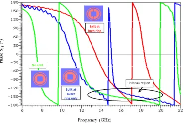
Fig. 10 Frequency response for three element designed.
It is clearly shown in Fig. 10 that, for the
first resonance, the gradient of the curve is
largely decreased when gap is introduced in the design. The bandwidth performance is improved from 26.9% to 67.6%. While for the second resonance, the phase slope is slightly improved from 19.8% to 20.3% only, however the plateau region is largely improved for the element with gaps.
Fig. 11 shows the current distribution
for concentric split ring square reflectarray
element. It is evident that the outer ring
determines the first resonance, while the
inner square ring determines the second
resonance. For the first resonance, it
is observed that the outer ring element is strongly excited, and for the second resonance, the inner square ring element is strongly excited.
Fig. 11 Surface current distribution (a) at 13.44 GHz and (b) at 18.36 GHz for a grounded
concentric split ring square reflectarray element
with a/R = 1 and I/O = 0.86. (O = 3.56 mm, a =
3.06 mm, R = 3.06 mm, periodicity = 10 mm, εr
= 3.54 and t = 1.524 mm)
3. RESULTS AND DISCUSSION
With the designed structure dimension
given in Section 2, the simulated reflection
phase versus ring radius of the proposed antenna is plotted and shown in Fig. 12, 13 and 14.
As stated before, a/R = 1 is used for further investigation on square element
resonant behavior. The reflection phase
versus square ring radius is plotted at the resonant frequency of 23.70 GHz. The linear phase range is 403° which is
sufficient enough for practical design [6]
while the gradient is 0.34 °/µm. Bandwidth performance for this element is 40.8%. Fig. 12 also shows that the maximum radius, R for the square ring is 4.46 mm. This is because the phase given at the higher R is not an acceptable resonance because the edge of the ring almost touched the next periodic array and caused short-circuit.
Fig. 12 Reflection phase versus outer ring
radius for single square element with a/R = 1
at 23.70 GHz. (periodicity = 10 mm, εr = 3.54
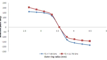
For concentric ring square element, I/O
= 0.86 and a/R = 1 is used in reflection
phase versus outer ring radius graph (Fig. 13) at the resonant frequencies of 7.48 GHz and 11.78 GHz. The linear phase range
achieved at the first resonance is 249° with the gradient 0.54°/µm and the phase range at the second resonance is 230° with the gradient 0.50/µm. Bandwidth performance
for first resonance is 26.9% and 19.8% for
the second resonance.
Fig. 13 Reflection phase versus outer ring
radius for concentric ring square element with I/O = 0.86 and a/R = 1 at 7.48 GHz and 11.78
GHz. (periodicity = 10 mm, εr = 3.54 and t =
1.524 mm)AA
While for the concentric split ring square element performance as in Fig. 14, I/O
and a/R ratio used is similar to the design (without gaps) at the resonant frequencies of 13.44 GHz and 18.36 GHz. The linear
phase range achieved for the first resonance
is 320°, which is acceptable for practical design [6] with the gradient 0.15°/µm and 464° (phase range) with gradient 0.33 °/µm at the second resonance. The bandwidth performance is 67.6 % and 20.3 % for the
first and second resonance respectively.
Fig. 14 Reflection phase versus outer ring
radius for concentric split ring square element with I/O = 0.86 and a/R = 1 at 13.44 GHz and
18.36 GHz. (periodicity = 10 mm, εr = 3.54
and t = 1.524 mm)
The performance for concentric split ring square element in Fig. 14 is improved from the design in Fig. 13 (without split).
As shown in Fig. 14, the curve at the first
resonance is largely improved where the plateau region is almost abolished and the curve is more linear. The frequency is shifted from 7.48 GHz to 13.44 GHz which then give the bandwidth improvement of about 40.7%.
For the second resonance, the plateau region is again improved but with a slight change. This results the bandwidth improvement ofabout 0.5% only. However, the new concept of split is still giving the better performance compared to the previous design with no split introduced. The second resonant frequency shifted from 11.78 GHz to 18.36 GHz.
The concentric element concept in the other hand is used to achieve a dual frequency operation compare to the single element performance which gives only one resonant frequency, as shown in Fig. 3. The phase range performance in a single element is bigger compared to
the first resonance of the concentric split
gradient which leads to the bandwidth performance is improved from 0.34°/µm to 0.15°/µm.
In concentric element design, the critical feature of mutual coupling should be taken care of because the design consist two elements which use the copper metal material. In this work, the gap between
the first and second element for concentric design is fixed at 0.5 mm, except for studies
in I/O ratio as shown in Fig. 6.
4. CONCLUSION
A new design of reflectarray element
for broadband dual frequency Ku-band application is proposed in this work which is the concentric split ring square element. By modifying the current distribution of the physical geometry of the basic concentric ring square element leads to a better phase variation and bandwidth.
This new design gives the good performance in bandwidth which is up to 67.6 % and 20.3 % in dual frequency operations. The phase range for the element is also in a good practical region which gives the value of 320° and 464° at both frequencies respectively.
This antenna is easy to fabricate and low cost. These features are very useful for worldwide portability of communication applications.
The authors would like to thank the MOSTI Secretariat, Ministry of Science, Technology and Innovation of Malaysia, Science fund: 01-01-02-SF0376, for sponsoring this work.
REFERENCES
1. Han C. M., “Dual-band Reflectarrays
Using Microstrip Ring Elements
and Their Applications with Various
Feeding Arrangements,” PhD Thesis,
Office of Graduate Studies of Texas A&M University, Texas, 2006.
2. Encinar J. A., “Design of Dual
Frequency Reflectarrays using Microstrip Stacked Patches of Variable
Size,” Electron. Letter, Vol. 32, No.
12, 1049-1050, 1996.
3. Huang J. and Encinar J. A., Reflectarray Antennas, John Wiley and Sons, United States of America, 2007.
4. Misran N., Cahill R. and Fusco V. F., “Reflection Phase Response of
Microstrip Stacked Ring Elements,”
Electron. Letter, Vol. 38, No. 8,
356-357, 2002.
5. Misran N., Cahill R. and. Fusco V. F,
“Design Optimisation of Ring Elements
for Broadband Reflectarray Antennas,” Proceeding IEEE Microwaves Antennas And Propagation, 2003. 6. Misran N., “Design Optimisation
of Ring Elements for Broadband
Reflectarray Antennas,” PhD Thesis,
Faculty of Engineering, The Queen’s University Belfast, Ireland, 2004. 7. Misran N., Cahill R. and Fusco
V.F., “Performance of a Broadband Ring Element Reflectarray,” Student Colloquium IEEE, The Queen’s University Belfast, Ireland, 2003. 8. Pozar D. M., Targonski S. D. and
Syrigos H. D., “Design of Millimeter
No.2, 287–296, 1997.
9. Rajagopalan H. and Samii Y. R., “Dielectric and Conductor Loss
Quantification for Microstrip Reflectarray: Simulations and
Measurements,” IEEE Trans. Antennas Propag., Vol. 56, No.4, 1192–1196,
2008.
10. Pozar D. M. and Metzler T. A.,
“Analysis of a Reflectarray Antenna Using Microstrip Patches of Variable
Size,” Electron. Letter, Vol. 29, No. 8,
657-658, 1993.
11. Han C. M. and Chang K., “Ka-band
Reflectarray Using Ring Elements,” Electron. Letter, Vol. 39, No. 6,