Modeling and Simulation of Induction Motor
in Stator and Synchronous Reference Frames
Praveen M G 1, Dr Sathyendra Kumar 2
PG Student, Dept. of EEE, NMAMIT, Nitte, Karkala, Udupi, India1. Professor, Dept. of EEE, NMAMIT, Nitte, Karkala, Udupi, India 2.
ABSTRACT: Induction motor is the commonly used electromechanical device in industrial, domestic and commercial
applications. In order to analyse transient response dq- modelling of induction motor is proposed in this paper. The three phase system is reduced to two phase system by this method so that it helps to control the motor parameter independently. The transient responses of induction motor is analysed in stator and synchronous reference frames by using dq-modelling. The MATLAB programming software is used to carry out the simulation in stator and synchronous reference frames.
KEYWORDS: DQ-Modelling, stator and Synchronous reference frame, MALAB.
I. INTRODUCTION
Induction motor are most used motor in the industries when compared to dc motor because of its ruggedness, low cost, seize, reliability and output per weight. Induction motors draws large current during starting and other transient operations and produces variations in the voltages and oscillatory torque and generate harmonics in the system. The dq-modelling is the best and accurate method to investigate transient problems. The transient responses are analysed using stationary and synchronous reference frames.
Now a days to model induction motor MATLAB software is used. The transient response of induction motor can be predicted by using this software. In this paper Matlab programming based modelling is proposed by using stator and synchronous reference frames. The conclusions are drawn based on the simulated results to justify the selection of particular reference frame.
II. DQ-MODELLING OF INDUCTION MOTOR
The following assumptions are made for induction motor modelling. 1. Air gap is assumed to be uniform.
2. Saturation and parameter changes are neglected. 3. Inductance versus rotor position is sinusoidal.
4. Stator and rotor windings are balanced and mmf distribution is sinusoidal.
The induction motor modelling is obtained by considering the two phase induction motor in direct and quadrature axis. Constant induction matrices are obtained from varied inductance matrix by replacing the actual rotor with fictitious rotor consisting of equal number of phase per turns and the voltage equations are given in equation 1 [1].
= (1)
Vts, Vss , Vtr , Vsr – Terminal voltages of stator and rotor along t-axis and s-axis respectively.
Its, Iss , Itr , Isr – Currents flowing through of stator and rotor coils along t-axis and s-axis respectively.
p – Differential operator, θr’ – time derivative angle between stator and rotor.
Lm- Mutual inductance, Ls & Lr –stator and rotor inductances respectively. Rst, Rro -Stator and rotor resistance respectively.
THREE PHASE TO TWO PHASE TRANSFORMATION
By establishing equivalence between three phase and two phase dynamic model of three phase induction motor can be derived from two phase motor. The three phase to two phase transformation is shown in figure1. Equivalence is based on equal mmf and current produced in the two phase and three phase windings. Assuming three phase windings have N1 turns and two phase windings 3N1/2 turns for equal current and mmf production is shown in figure 1. It is assumed that t-axis lagging the r- axis by an angle .The relationship between sto and rby currents is given in equation 2 [1].
= * (2)
Figure 1: Two and three phase stator windings.
The above equation can be represented as
(3)
[Tryb] is also valid for flux linkages and voltage in machines.
GENERALIZED MODEL IN ARBITRARY REFERENCE FRAME
The stator and rotor variables are represented in common reference frame in order to analyse the induction motor drive system. The induction motor model equations in arbitrary reference frames is given equation 4 [1].
STATIONARY REFERENCE MODEL
In stationary reference frame, the reference frame speed is that of the stator, i.e. .This reference frame is preferred whenever stator voltages are unbalanced and discontinuous and rotor voltages are balanced. The voltage equations of induction motor in stationary reference frame is obtained by substituting in equation 4 and given in equation 5 [1].
= (5)
SYNCHRONOUS REFERENCE FRAME MODEL
In synchronous reference frame, the reference frame speed is that of the stator supply frequency i.e. .The synchronous reference frame is used to study the dynamic and transient stability of the system. The synchronous reference frame is used to study the dynamic and transient stability of the system. The equations of induction motor in synchronous reference frame is obtained by substituting in equation 4 [1].
= (6)
ELECTROMAGNETIC TORQUE
Electromagnetic torque is the ratio of air gap power developed to the mechanical rotor speed in rad/sec. The electromagnetic torque is given in equation 7 [4].
(7)
Where P is the number of poles and Tel is the instantaneous electromagnetic torque.
COMPUTATIONAL EQUATIONS
The three phase induction motor model equations are represented in terms of state space form [2]. The following equations are used to get simulation results which are represented in state space form [6] [2].
(8) (9) (10) (11) Where (12) (13) (14)
The current values are obtained by substituting the flux equations in equations 15-18.
(18)
III.SIMULATION RESULTS
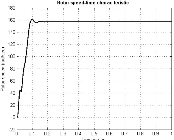
The following Squirrel cage induction motor parameters are consider for the simulation analysis. Rs =1.2 ohm, Rr =1.2 ohm, Ll =6e-3 H, Llr=6e-3H, Lm =203.7e-3H, J=0.02 kg – m2, B=0, P=4, V =415V, f =50Hz. Figures from (2) to (7) shows the simulation results using MATLAB Programming software. The torque and rotor speed characteristics shown in figure 2 and figure 3 and are remain same irrespective of reference frame. Stator current of stationary and synchronous reference frames are shown in figure 4 and figure 5 [3] [5].The torque vs speed characteristics of stationary and synchronous reference frames are shown in figure 6 and figure 7.
Figure 2: Rotor speed (rad/sec) vs time characteristics
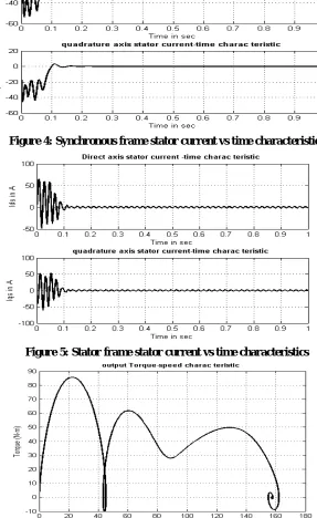
Figure 4: Synchronous frame stator current vs time characteristics
Figure 5: Stator frame stator current vs time characteristics
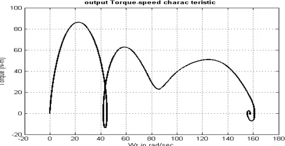
Figure 7: Torque vs speed characteristics of synchronous frame.
IV.CONCLUSION
The modelling of induction motor in stator and synchronous reference frames are analysed and presented in this paper. The simulation are carried out in Matlab software in synchronous and stator reference frames and are analysed in terms of rotor speed, torque and stator currents. The torque and speed remains same irrespective of reference frame and stator currents of stator and synchronous reference frames will vary.
REFERENCES
[1] R. Krishnan, ―Electric motor drives modelling, analysis and Control, ǁ 1st ed., 2001 Prentice-Hall International, New Jersey.
[2]P. C. Krause, O. Wasynczjk, ―Analysis Of Electrical Machinery, ǁIEEE Press, New York.
[3] C.M. Ong. 1998. Dynamic simulation of Electric Machinery. Prentice Hall PTR, Upper Saddle River, N. J. Publication. [4] B. K. Bose. 2007. Power Electronics and AC Drives. Pearson Prentice Hall.
[5] The MATLAB compiler user’s guide in Math works Handbook. Math Works.