Application of EMC3-EIRENE to Estimation of Influence of a
Liquid Metal Limiter on an LHD-Type Fusion Plasma
∗
)
Gakushi KAWAMURA
1,2), Junichi MIYAZAWA
1,2), Takuya GOTO
1,2),
Mamoru SHOJI
1), Suguru MASUZAKI
1,2), Yasuhiro SUZUKI
1,2)and Yuhe FENG
3)1)National Institute for Fusion Science, National Institutes of Natural Sciences, Toki 509-5292, Japan 2)Department of Fusion Science, Graduate University for Advanced Studies (SOKENDAI), Toki 509-5292, Japan
3)Max-Planck-Institut für Plasmaphysik, D-17491 Greifswald, Germany
(Received 28 December 2017/Accepted 25 March 2018)
Recently, a new limiter concept with liquid metal for a helical fusion reactor was proposed. This work present a modeling study to understand the influence of the limiter to the plasma and to find critical parameters for the liquid limiter concept. EMC3-EIRENE code is applied to a limiter configuration of a vertical column formed with plane surfaces at the inboard side of the Large Helical Device (LHD). The calculation results indicate that heat load on the helical divertor plates is significantly reduced when the limiter is inserted into the ergodic layer even without impurities. However, the influence of impurity radiation is too large in some cases. In order to achieve a large reduction of divertor flux and to avoid a large reduction of core electron temperature, parameter scans with limiter position and sputtering yield were performed. The results suggest that the limiter position is a critical parameter for acceptable degradation of the core and sufficient reduction of divertor flux.
c
2018 The Japan Society of Plasma Science and Nuclear Fusion Research
Keywords: EMC3-EIRENE, modeling, liquid metal, limiter, divertor DOI: 10.1585/pfr.13.3403034
1. Introduction
The issue of heat flux on plasma-facing components is crucial for a future fusion reactor. New concepts of tokamak divertor systems have been proposed utilizing modifications of the magnetic field structure and the di-vertor plates. A concept design of an advanced didi-vertor, REVOLVER-D, for a helical fusion reactor has been pro-posed based on Large Helical Device (LHD) [1]. This con-cept design uses a shower of melting tin as a plasma-facing component. The shower catches high heat flux from the plasma and reduces heat flux to the helical divertor plates. High heat-removal performance of liquid metal makes it possible to install the shower in the ergodic region. The melting tin shower plays the role of a poloidal limiter to diminish the divertor legs. However, there is no experi-mental knowledge of such a strong plasma shaping with a limiter in LHD, and it is difficult to realize such a limiter in a usual operation campaign of LHD. Therefore, modeling studies are required to estimate the liquid limiter’s perfor-mance and its influence to the peripheral plasma, and the divertor plates.
2. Modeling of a Liquid Metal Limiter
The shower limiter of REVOLVER-D consists of many fine liquid flows, and precise modeling requires fineauthor’s e-mail: [email protected]
∗)This article is based on the presentation at the 26th International Toki
Conference (ITC26).
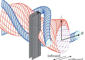
Fig. 1 A schematic figure of the box-like plane limiter in the model. A plasma shape (red), two helical coils (blue), and a limiter surface (black) are depicted.
resolution of the calculation grid system. Therefore, we obscure the fine structure and use a box-like plane limiter, as shown in Fig. 1. The limiter in the model has sufficiently long inz-direction to cut the plasmas including the divertor legs in the inboard side. The toroidal width of the limiter is 4◦ corresponding to approximately 8 cm when the limiter is placed in the ergodic region. The radial position of the limiter is defined by two coordinate values of both edges of the surface, RwandRp, as shown in Fig. 2. The
wall-side position of the limiter is fixed atRw =2.3 m and the
plasma-side positionRp is a free parameter in this work.
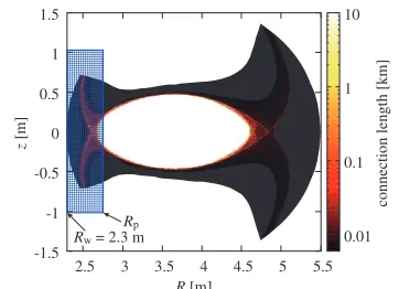
The connection length map is also shown in the figure to show where the limiter cuts the plasma. The limiter edge atR =Rpcuts the LCFS in the white region in the core.
c
2018 The Japan Society of Plasma
Fig. 2 Connection length distribution with a limiter surface in the horizontally elongated cross section. The blue hatched region represents the position of the limiter. The coordinateRwandRpis the radial position of both edges of the limiter surface. The limiter position in the figure is atRp=2.75 m.
The plasma is terminated by the limiter surface with Bohm condition and the deuterium ions are released as deuterium molecules and atoms with the same process as on the diver-tor plates. We use the open diverdiver-tor configuration and the standard LHD magnetic field configuration with the axis position atRax = 3.6 m. The first wall geometry and the
size of the device are the same as LHD.
We employed EMC3-EIRENE code [2–4] to model the plasma with the limiter. The code describes a plasma with Braginskii-type two fluid equations along magnetic field lines with cross-field diffusion and neutrals with a Boltzmann-type kinetic equation. We used typical cross-field diffusion coefficientsD⊥ =0.5 m2/s,D
imp⊥ =1 m2/s,
andχe⊥ = χi⊥ = 1 m2/s for deuterium plasma, impurity
ion, and electron/ion energy, respectively. The code in-cludes energy interactions between the impurity and the electron due to ionization, recombination, and radiation. We used ADAS database [5] for impurity atomic pro-cesses. The electron density at the core boundary atR =
2.895 m and the heating power are fixed to 5×10¹⁹/m3and 10 MW, respectively. Details of the grid system and the modeling parameters are found in papers [6, 7].
3. Influence of Limiter Position
We made a parameter scan of the plasma-side limiter positionsRp =2.55, 2.6, 2.7, 2.75, 2.8, and 2.85 m to see
influence of the limiter position to the plasma transport. We compare electron density and electron temperature dis-tributions at the same toroidal position as the limiter be-tween with and without the limiter in Figs. 3 (a) and 3 (b). The divertor legs at the inboard side cause large particle and heat fluxes on the divertor tiles [8] without the limiter but are completely removed by the limiter. Plasmas in the other legs are significantly weakened by the limiter but do not disappear.
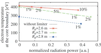
Dependence of the electron temperature on the limiter
Fig. 3 Electron density (a) and temperature (b) distributions without and with the limiter.
Fig. 4 Dependence of electron temperature at the core boundary and the wall surfaces on the limiter positionRp.
positionRpis shown in Fig. 4. Impurities are not take into
Fig. 5 Dependence of particle and heat flux losses on the limiter position Rp. Surface recombination energy is included in the heat loss on surfaces and ionization energy is ex-cluded in the heat loss due to neutral particles. The heat loss due to neutral particles includes charge exchange and radiation from deuterium.
Normalized flux losses of particle and heat are shown in Figs. 5 (a) and 5 (b), respectively. The loss on the lim-iter increases and the loss on the divertor decreases when the limiter position is shifted toward the core plasma. The fraction of heat loss on the divertor rapidly decreases even when the limiter surface is far from the LCFS. The heat flux is reduced to 41% at the positionRp =2.6 m and to
26% at the positionRp = 2.65 m. Those results suggest
that large reduction of heat flux to the divertor plates is possible without significant degradation of the core tem-perature by choosing the limiter position in the range of 2.6 m<Rp<2.7 m.
Distributions of fluxes and plasma parameters on the limiter surface are shown in Figs. 6 (a), 6 (b), 6 (c), and 6 (d). The center region of the limiter is closest to the core plasma but has lower particle flux and lower heat flux than the other regions because the magnetic field lines are in-clined on the surface of the center region. The fluxes on the side surfaces of the limiter have wide distribution along the radial direction when the limiter is outside the LCFS. On the other hand, the flux distributions have significant peaks on the side surfaces near the center region when the limiter is placed beyond the LCFS as shown in the case of
Rp=2.8 m.
4. Influence of Impurity
Impurity is another essential factor leading to degra-dation of the core plasma performance. Therefore, esti-mation of impurity flux released from the limiter and its transport in the plasma are critical issues. REVOLVER-D uses tin because of its much lower vapor pressure than other metallic materials with low melting point [1, 9]. A rough estimation of vapor flux is given byPv/
√
2πmkT
under the assumption of an equilibrium of particle flux on
Fig. 6 Distributions of (a) heat flux density, (b) particle flux den-sity, (c) electron temperature, and (d) electron density on the limiter surface. Results with three different cases,
Rp =2.6, 2.7, and 2.8 m, are shown together. The green dotted lines represent the corner positions of the limier surfaces.
the surface. The vapor pressure, atomic mass, Bolzmann constant, and surface temperature are denoted byPv,m,k,
andT, respectively. When the surface temperature is less than 1000◦K the vapor pressure is less than 10−5 Pa and
the particle flux is less than 10−6 of a typical deuterium
ion flux. That means the vapor flux is similar to a sputter-ing flux with a sputtersputter-ing yield of the order of 10−6. The vapor flux arises from the surface with high temperature and, therefore, it can be much larger than the plasma wet-ted area. If the high temperature area is 100 times larger than the plasma wetted area, the corresponding sputtering yield becomes 10−4.
The physical sputtering yield of tin bombarded by deuterium is found in paper [10]. The authors suggest a strong dependence on surface temperature especially above the melting point. The sputtering yield is of the order of 10−2 with solid tin and of the order of 10−1 with
melt-ing tin. In any case, the sputtermelt-ing flux would be larger than the vapor flux. Sputtering of melting metal is not well investigated, and it seems to be difficult to estimate a sput-tering yield for a certain surface temperature and plasma parameters. In this study, we use 1% of sputtering yield as a reference although this amount may be an underestima-tion.
Fig. 7 Dependencies of electron temperature at the core bound-ary and at the wall surfaces for different impurity species.
Fig. 8 Electron temperature at the core boundary. Values near the marks are sputtering yields of germanium.
available in the ADAS database. Accordingly, we carried out a parameter scan of homologous elements of tin, i.e., carbon, silicon, and germanium. We modified the EMC3-EIRENE code to use the fixed sputtering yield on the lim-iter surface and no sputtering on the divertor plates. Elec-tron temperature at the core boundary and the wall surfaces is shown in Figs. 7 (a) and 7 (b), respectively. Energy loss due to radiation from the impurity causes decrease of elec-tron temperature. The temperature reduction is not signif-icant with the limiter atRp =2.6 m but becomes large for
Rp > 2.65 m. Carbon and silicon have a relatively small
impact on the core electron temperature, but germanium has a large impact. Reduction of electron temperature of the wall surfaces also occurs. Impurity ions with a higher atomic number cause larger radiation in general. There-fore, tin would have larger radiation and larger influence on the core electron temperature.
We investigated the impact of impurity on the core electron temperature with different sputtering yields. Fig-ure 8 shows temperatFig-ure as a function of impurity radia-tion power normalized by the heating power. In the case of largeRp,>2.65 m, radiation power becomes large even for
1% of sputtering yield. On the other hand, in the case of
Rp=2.6 m, radiation power is much smaller than the other
cases of the same sputtering yield, and does not cause large reduction of core electron temperature.
In order to avoid a significant influence upon the core
plasma, the limiter position should be sufficiently outside the LCFS. Our results suggest Rp < 2.65 m. However,
these results depend on the sputtering yield and impurity species. Development of sputtering model and impurity database is required to achieve quantitative results. Also, impurity transport is affected by plasma parameters such as electron temperature and density. Therefore, further in-vestigation including development of physical models are necessary.
5. Conclusions
The first modeling of an LHD-type fusion plasma with a box-like limiter at the ergodic region has been conducted and its application to estimation of influence of a liquid metal limiter on the plasma has been presented. Signifi-cant reduction of divertor flux is confirmed as a result of flux removal by the limiter. Particle and heat flux on the divertor plates are reduced to one half even in the case of a modest limiter position,Rp =2.6 m, and to almost zero
in the case of a position deeply in the plasma across the LCFS,Rp=2.8 m. In order to avoid large drop of the core
electron temperature, the model suggests the range of the limiter position,Rp<2.7 m.
In the investigation of impurity, tin cannot be used for the modeling because of the lack of a database. However, a sensitivity study has been performed with homologous elements of tin. Impact of carbon and silicon on the core electron temperature is relatively small However, germa-nium has strong impact. The model suggestsRp <2.65 m
as an acceptable range, where the heat flux on the divertor plates are reduced to one half or one third. However, we note that tin would have stronger impact. Also our estima-tion depends on a sputtering yield, which has not yet been clarified for liquid metal.
From the above investigations, significant reduction of heat flux on the divertor plates and relatively small influ-ence on the core electron temperature seems to be obtained in the range of 2.6 m<Rp<2.65 m. That finding suggests
the necessity of an adjustment mechanism of the limiter position, for example, switching of each liquid flow. Influ-ence of impurity must be clarified with reliable sputtering model and database. Control method of impurity transport in the plasma and in the liquid metal shower is a critical issue from the engineering point of view.
Acknowledgments
This work was supported partly by JSPS KAK-ENHI Grant Number 16K18340 and performed under the auspices of the NIFS Collaboration Research program (NIFS16KNST100).
[5] OPEN-ADAShttp://open.adas.ac.uk/
[6] G. Kawamuraet al., Contrib. Plasma Phys.54, 437 (2014). [7] G. Kawamuraet al., “Three-dimensional impurity transport modeling of neon-seeded and nitrogen-seeded LHD