Gupta et al. World Journal of Engineering Research and Technology
EXPERIMENTAL FREQUENCY RESPONSE FUNCTIONS AND
THEIR USE IN DEVELOPING UPDATED FINITE ELEMENT MODEL
Atul Gupta*1, Ajay Vardhan2 and Anant K. Gupta3
1,3
Department of Mechanical Engineering, SGSITS, Indore 23-Park road, Indore, 452003.
2
UIT RGPV Bhopal MP 462036.
Article Received on 14/09/2017 Article Revised on 05/10/2017 Article Accepted on 26/10/2017
ABSTRACT
The dynamic characteristics of a system include its modal parameters
(natural frequencies, damping factors, mode shapes) as well as
frequency response functions (FRFs). The important characteristics of
the frequency response are its magnitude and phase. The magnitude
provides the information about the resonance and anti-resonance
frequencies of system, while the phase shows the lag in response and stimulus signal.
Determining frequency response function of dynamic system is of great interest in recent
years. This can be achieved through conducting some experiments as well as using
theoretically/finite element method. This work reports the work involving estimation of both
experimental FRFs and theoretical FRFs and the co-relation between the two. Finite element
analysis is now a days widely used tool to carry out numerical analysis and the same has also
been used in this work. In the process of correlation of experimental and finite element
results, the issue of modelling inaccuracies of structures especially joint parameters has been
addressed. The issue of coupling between bending and torsional mode has also been
discussed.
KEYWORDS: Frequency response function, resonance and anti-resonance frequency, mode shapes, signal processing, Lab VIEW, ANSYS, point receptance, cross receptance.
World Journal of Engineering Research and Technology
WJERT
www.wjert.org
SJIF Impact Factor: 4.326*Corresponding Author Atul Gupta
INTRODUCTION
Vibratory motion in machines and structures are of frequent concern in engineering practices.
In general, vibrations are undesirable in machines and structures as they are responsible for
producing excessive stresses, wear, unwanted noise and premature failure of the components
by way of looseness or due to fatigue.
Modal analysis is used to find out the dynamic characteristics of structures. These include
natural frequencies, damping factors and mode shapes. These properties help in
understanding the dynamic behaviour of structures. The conditions of resonance can be
prevented by the knowledge of natural frequencies.
Modal analysis is a tool to determine the dynamic characteristics of structures. It can be
performed both theoretically and experimentally (Ewins (2000b)). Experimental modal
analysis consists of exciting the structure with a force transducer and sensors are used to
measure the resulting response. The work by Ewins (2000a) can be referred to for details of
procedures of modal testing. Structures can be non-spinning like stationary structures or
spinning like in case of rotating machines. Chouksey, Dutt et al. (2012) carried out modal
testing of spinning structures.
In recent years, various research studies are going to actively control the unwanted vibration
of flexible structures by utilizing the piezoelectric actuators. Pradhanand Modak (2012).
Proposed improved FRF based FE model updating method for updating mass and stiffness
matrices. Gillich and Praisach (2014) proposed a new method based on natural frequency to
detect and locate the damage in beam like structure. Arora(2014) proposed the new structural
damping identification method using normal frequency response function.Friswell and
Mottershead (1999b) proposed a method for replacement of unknown stiffness with rigid
connections in two systems of equations from a finite element model. Besides the above
mentioned work, numerous works has been carried on finding the frequency response of the
system.
Merkel, Gatzwiller et al. (1998) performed experimental modal analysis for more accurate
Anti-Resonance frequency (ARF) of the building structure during the earthquake
condition.Chouksey, Dutt et al. (2010) obtained the complete model and more accurate modal
analysis of rotor shaft systems by taking into account the rotating shaft material damping
force and the influence of the damping forces on the mode-shapes and directional frequency
response.Friswell and Mottershead (1999a) proposed a method for the replacement of
unknown stiffness with rigid connections in two systems of equation from a finite element
model and from measured response functions.
In the literature surveyed as available so far, the studies involving the correlation of
experimental results with theoretical results are found to be limited. Moreover, in the existing
literature the studies showing the coupling in torsional and lateral degrees of freedom are not
found.
Based on the literature review, it was decided to carry out experimental and numerical studies
on modal analysis. The issue of developing the accurate finite element model is also
addressed. In the Present work correlation of experimental and finite element results, the
issue of modelling inaccuracies of structures especially joint parameters has been addressed.
The issue of coupling between bending and torsional mode has also been discussed.
METHODOLOGY
By studying the various research works and literature, we identify the problem and for this
the experimental modal analysis of cantilever beam is carried out in Lab VIEW to determine
its frequency response experimentally. Modelling and simulation of the cantilever beam is
carried out in ANSYS APDL to find its FRF and mode shapes. Updating the simulation
model and comparing its result with experimental FRF.
RESULTS
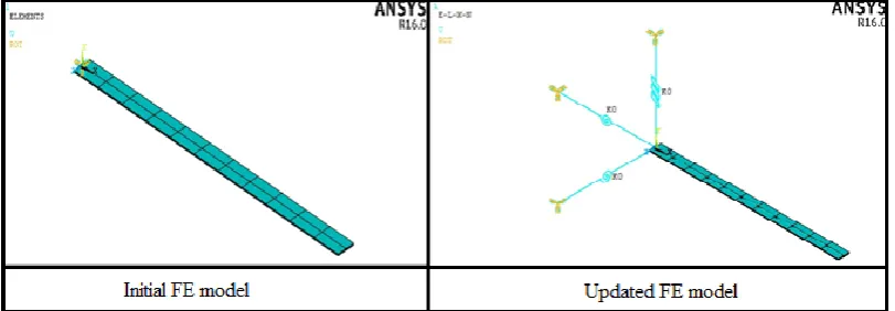
The Figure 0.1 shows the initial and updated FE model. The initial FE model refers to the
cantilever beam with fixed support. While the updated FE model is modelled on the basis of
observation that the cantilever beam used in experiment is not rigidly fixed at support and
Figure 0.1: Initial and updated FE model.
Figure 0.2: Comparison of experimental FRF andinitial FE model FRF.
Initial FE model has certainly some inaccuracies, as is reflected through comparison of FRFs
shown in Figure 0.2. These inaccuracies as such may be either in inertial or stiffnesses.
However, inertia is generally modelled correctly, as we have fair idea of density of the
material. Further, with good idea of material properties like modulus of elasticity, Poisson’s
ratio the chances of inaccuracies of bending stiffness of beam are also not there. However,
support/joint stiffnesses are generally not known and this forms the inaccuracies in the model.
Estimation of the same is further addressed in the work. Regarding this, an updated finite
element model has been modelled in the ANSYS APDL. The updated model is modelled by
an observation that the cantilever beam used for experiment is not rigidly fixed at its end and
thus the finite element model is updated by changing its boundary condition (support).
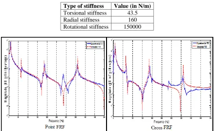
The cantilever beam is supported by the spring along the x, y, and z-directions. To provide
Table 0-1: Spring stiffness value.
Type of stiffness Value (in N/m)
Torsional stiffness 43.5
Radial stiffness 160
Rotational stiffness 150000
Figure 0. 3: Comparison of experimental FRF and updated FE model FRF.
From the Figure 0. 3it has been observed that the experimentally measured FRF matches with the updated finite element model FRF. Although, it has been observed that there is a mode
observed in the experimental result and is not observed in the simulation result this is due to
the presence of coupling between bending and torsion in the real- system and thus due to
uncoupling in the simulation the torsion mode is not observed in the frequency response of
the cantilever beam. To justify this, the torsion mode corresponding to natural frequency
279.387 is shown in Figure 0.4.
Table 0-2 Comparison of natural frequencies.
Experimental Data Simulation Data Percentage Error
Before update After update Before Update After Update
10.24 11.5 10.24 10.95 00.00
66.56 72 65.13 07.55 02.19
186.36 208.5 184.32 10.61 01.10
359.50 432 360.65 16.78 00.31
It can be seen from the Table 0-2 that the percentage error after updating FE model is
considerably reduced.
CONCLUSIONS
In this work, experimental and finite element analysis of the cantilever beam has been carried
out. The objective of the work is to obtain the frequency response of the cantilever beam
experimentally and using numerical simulation. An updated finite element model is shown by
changing the boundary condition (support) of cantilever beam and the effectiveness of the
updated model is demonstrated by comparing with the experimentally measured frequency
response. It can be concluded from the work that there is remarkable change in the frequency
response by changing the boundary conditions of the beam.
The importance of various terms related to signal processing are also discussed. The point
FRF and cross FRF measured are plotted and the experimental natural frequencies are
measured through the FRFs. The plots of coherence showed the accuracy of the FRFs
measured.
The issues of modelling inaccuracies are discussed in the work. The joint parameters may be
the main sources of inaccuracies in a finite element model
The work also included comparison of experimental FRFs and finite element model FRFs.
The comparison of measured FRFs and initial FE model FRFs results showed large variation.
However, with updating the FE model the variations are minimized considerably.
The comparison of measured natural frequencies has been made with the initial as well as
updated FE model. This comparison in case of initial FE model showed large variation,
which is reduced considerably in case of updated model
REFERENCES
1. Arora, V. "Structural damping identification method using normal FRFs." International
Journal of Solids and Structures, 2014; 51(1): 133-143.
2. Chouksey, M., et al. "Influence of rotor-shaft material damping on modal and directional
frequency response characteristics." Proceedings of ISMA- Katholieke Universiteit,
Leuven, Belgium, 2010; 1543-1557.
3. Chouksey, M., et al. Experimental modal analysis studies for spinning rotor system.
VETOMAC-VIII, Gdansk, Poland, 2012.
4. Ewins, D. J. "Basics and state-of-the-art of modal testing." Sadhana, 2000; 25(3):
207-220.
5. Ewins, D. J. Modal testing: Theory, practice and application, Research Studies Press,
Baldock, Hertfordshire, England, 2000.
6. Friswell, M. I., et al. Frequency response functions and finite element equations with
rigid-body constraints, and their application in model updating, Society for Experimental
Mechanics Bethel, CT, 1999; 1: 654-659.
7. Friswell, M. I., et al. Frequency response functions and finite element equations with
rigid-body constraints, and their application in model updating. 17th Int. Modal Analysis
Conf. (IMAC). Bethel, 1999.
8. Gillich, G.-R., et al. "Modal identification and damage detection in beam-like structures
using the power spectrum and time–frequency analysis." Signal Processing, 2014; 96:
29-44.
9. Lien, N. C., et al. Identification of Anti-resonance Frequency in Buildings Based on
Vibration Measurements. 12th World Conference on Earthquake Engineering. Auckland,
NZ, 2000.
10.Merkel, R. C., et al. Important Aspects of Precise Driving Point FRF Measurements
Using a Mechanical Impedance Head Sensor Proceedings of the Sixteenth International
Modal Analysis Conference. Santa Barbara, California, USA, 1998; 795-799.
11.Pradhan, S., et al. "Normal response function method for mass and stiffness matrix
updating using complex FRFs." Mechanical Systems and Signal Processing, 2012; 32: