ISSN (e): 2250-3021, ISSN (p): 2278-8719
Vol. 08, Issue 7 (July. 2018), ||V (IV) || 50-56
THD Reduction in Multi-Level Inverter by Solving SHE
Equations Using Improved Optimization Technique
Meghana Mc
1, Dr W M Sivakumar
2, Anguraja R
3 1Visvesvaraya TechnologicalUniversity, Department of Electrical and Electronics Engineering, Don Boaco Institute of Technology, Bangalore, Karnataka, India,
2 Visvesvaraya Technological University, Department of Electrical and Electronics Engineering, Don Bosco
Institute of Technology, Bangalore, Karnataka, India,
3
Visvesvaraya Technological University, Department of Electrical and Electronics Engineering, Don Bosco Institute of Technology, Bangalore, Karnataka, India,
Corresponding Author: Meghana Mc
Abstract:
The multilevel Inverter is used for high power utility applications. To get AC output waveforms with low harmonic content, a set of non- linear transcendental equations known as selective harmonic elimination equationsare solved. Thus lower order harmonics are eliminated and the higher order harmonics are filtered out in SHE techniques .The switching angles are optimized with new proposed optimization technique. Modulation index m, is changed over a range to get required output waveform. THD vary with modulation index values. In this paper, the THDs and output waveform of single phase full-bridge inverter using SHE scheme with varying the modulationindex isobtainedIndex Terms
– Cascaded H-Bridge multilevel inverter, Total Harmonic Distortion-THD, Selective Harmonic Elimination-SHE, Modulation index mi, Optimization techniques.--- --- Date of Submission: 06-07-2018 Date of acceptance: 23-07-2018 --- ---
I.
INTRODUCTION
Extensive use of renewable resources, has given opportunity for innovations and enhancements in field of inverters.A multilevel converter is used to achieve high power ratings, reduce harmonics, dv/dt stresses, and stresses in the bearings of a motor. Different multilevel converter topologies used are; i) diode clamped, ii) flying capacitors, and iii) cascaded or H-bridge. A cascade multilevel inverter is a power electronic device, which synthesize a desired AC output from several levels of DC inputs. Referring to the literature reviews, the cascaded multilevel inverter (CMI) is the most feasible topology for medium& high power applications due to its modularization and extensibility. Cascaded multilevel inverter is composed of several single phase H-Bridges connected in series, thereforeits often called as, H-bridge cascaded multilevel inverters.It has varies application such as motor drives, renewable energy, active powerfilters, Flexible AC Transmission System (FACTS), HVDC and others[1]. With specific modulation techniques, required harmonics can be eliminated.
Reduction in harmonics is achieved, byfinding optimum switching angels of converters. There are many modulation techniques studied to reduce harmonic contents inthe converters. Different methods emerged: sinusoidal Pulse Width Modulation (PWM), Space Vector PWM, Selective Harmonic Elimination (SHE), and Space Vector Modulation (SVM)[2]. However, PWM techniques do not eliminate low order harmonic.
It is found that SVM and SHE are the most widely used modulation techniques for all the types of multilevel inverters.The popular selective harmonic elimination method is based on the harmonic elimination theory[3],[4].SHE techniques comprises the mathematical modelling of output voltage waveform and solving nonlinear transcendental equations which contain trigonometric terms for switching angles based on the amplitude of the fundamental wave of the output voltage, the order and number of the eliminated harmonics.
difficult. In [10] ,the most popular Newton-Raphsonmethod for solving these equations is proposed. This method gives optimum result only for proper initial guess.
The new technique proposed in this paper , uses both cauchy (steepest descent )and NR method algorithm for convergence. A 7-level inverter using five H-bridges per phase in series is analysed , and it is shown that for a given range of modulation index , switching angles can be computed. Desired fundamental voltage V1 is obtained, with elimination of 5th, 7th, and 9th, components. The validity of the proposed methods are made by comparing the results with experimental results
II.
SYSTEM DESCRIPTICTION
Cascade Multilevel Inverter (CMLI) is the most popular topology in the group of multilevel inverters and multipulse inverters. It requires less number of components compared to diode-clamped and flying capacitors type multilevel inverters and no transformer is required as compared to multipulse inverter.
A. Cascaded H-Bridge Multilevel Inverters (CHB-MLI) topology
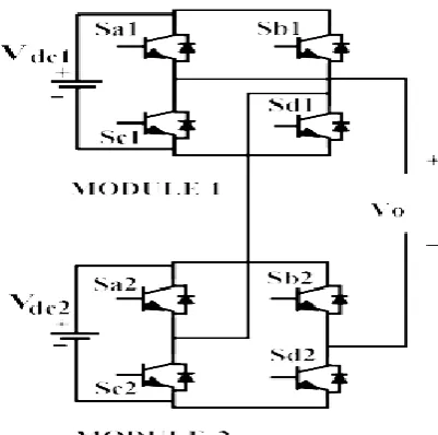
Fig 1,shows cascaded multilevel inverter, it consist of H-bridge modules connected in series.The absence of clamping diodes or voltage balancing capacitors, and easy adjustment of the number of output voltage levels are some advantages of CMLI in comparison with other topology. Switching devices switch ON and OFF once per cycle to overcome the switching loss problem [3].Each H-bridge generates three different voltage: +Vdc, 0, and −Vdc. All CMIL produces staircase wave and 2S + 1 number of output voltage levels are generated, where S is the number of dc sources.
Fig 1: Single phase cascaded multilevel H- bridge inverter
Fig.2. 5-level cascaded multilevel inverter
Fig. 3.5-level CMLI output voltage waveform.
III.
CASCADED MULTILEVEL H-BRIDGE INVERTER MODELLING USING SHE
TECHNIQUE
Fourier series expansion of the staircase wave of CMLI is given as
𝑉 𝑤𝑡 = 𝑉𝑛sin(𝑛𝑤𝑡 ∞
𝑛=1
) (1)
where, Vn is the amplitude of the nth harmonic. Switching angles are limited between zero and 90o (0 ≤ xi< π/2)[11]. Because of odd quarter-wave symmetric characteristic, even order harmonics become zero. Consequently, Vnbecomes
𝑓 𝑥 = 4𝑉𝑑𝑐
𝑛𝜋 cos 𝑛𝑥𝑖
𝑆
𝑖=1
, 𝑓𝑜𝑟 𝑜𝑑𝑑 𝑛𝑠
0, 𝑓𝑜𝑟 𝑒𝑣𝑒𝑛 𝑛𝑠
(2) where , Vdc is the level of dc voltage, S is number of H-bridge
The objective of SHE method is to reduce the lower order harmonics and other remaining harmonics are removed with filter[12].In this paper, a 7-level inverter is chosen for case study and its low-order harmonics (fifth and seventh) are eliminated. Triplen harmonics disappear in three-phase applications.
4𝑉𝑑𝑐
4𝑉𝑑𝑐
𝜋 cos 5𝑥1 + cos 5𝑥2 + cos 5𝑥3 = 0 (4)
4𝑉𝑑𝑐
𝜋 cos 7𝑥1 + cos 7𝑥2 + cos 7𝑥3 = 0 (5)
Equation (2) is the expression for the fundamental voltage in terms of switching angles. The modulation index mi is the ratio of the fundamental output voltage V1 to the maximum obtainable fundamental voltage Vmax[2];.The maximum voltage ,when all the switching angles are zero, Vmax=4𝑠Vdc𝜋 Therefore the expression for mi is
mi=𝜋𝑉1 4𝑠𝑉𝑑𝑐 (6)
Equation (3) to (5) is non-linear transcendental equation and it is solved for switching angles for the a range of
mi(0 to 1)
IV.
PROPOSED OPTIMIZATION TECHNIQUE TO SOLVE SHE EQUATIONS
The negative of the gradient vector as a direction for minimization was first made by Cauchy in 1847 . In this method, initial point of x1 is assumed and iteratively moved along the steepest descent direction ,to reach optimumpoint. The NewtonRaphson method, converges fast when initial guess of Xi is close to the optimum point X∗. The new proposed optimizationmethod is combination of both the steepest descent and NR methods. In this method diagonal elements of the Hessian matrix is modified , [Ji] by multiplying it a positive constant
p. The value of pidecreases from a large value to zero, the characteristics of the search method change from those of a steepest descent method to those of the NR method.
A. Algorithm of proposed optimization technique
1. Start with an arbitrary initial point x1 and constants p1(highest value), 2. Set the iteration number as i = 1.
3. Compute the gradient of the function, ∇Fi = ∇F (xi). 4. Test for optimality of the point xi . If ||∇Fi || = ||∇F (xi)|| ≤ ε,
If, xi reaches optimum point ,then stop the process. Otherwise, go to step 4. 5. Find the Xi+1 as Xi+1 =Xi − [[Ji]] + pi [I ]]−1 ∇Fi
6. Compare the values of Fi+1 and Fi. 7. If Fi+1 < Fi , go to, step 8
If Fi+1 ≥ Fi, go to step 9.
8. Set pi+1 = b1*pi, i = i + 1, and go to step 2. 9. Set pi = b2*pi and go to step 4.
By following the above algorithm steps, all possible solution sets, when they exist, can be computed without any computational complexity.
V.
IMPLEMENTING PROPOSED OPTIMIZATION METHOD ON 7-LEVEL INVERTER
A. 7-level CHB-MLI driving angles
Toncalculate the switching angles, the above mentioned proposed optimization technique is programmed using MATLABsoftware. Initial values are guessed. Possible output for nine level inverters iscalculated for different mi values.
Table 1: SWITCHING ANGLES CALCULATED for different modulation index of 7 levels inverter
m X1 X2 X3
0.35 35.5532 54.2994 69.3368 0.387 26.4589 52.8006 64.2048 0.451 13.4068 36.3693 61.5077 0.489 11.8817 25.9052 55.4652 0.501 14.038 20.9695 53.0517
m X1 X2 X3
Table 1, shows all the driving angles of 7levels inverter, the same is verified on Simulink. It is observed that the driving angles are not obtained for few modulation indexes.
B. Harmonic analysis using Simulink inverter model
SHE technique is used for finding different switching angles that can be used for removing certain harmonic from the output waveform of the CHB-MIL.angles obtained in above proposed optimization technique is validated by simulating CHB-MIL and harmonic analysis is carried out to find the percentage content of selected harmonic in the output waveform The harmonics that are considered for elimination are 5th, 7th and 9th.
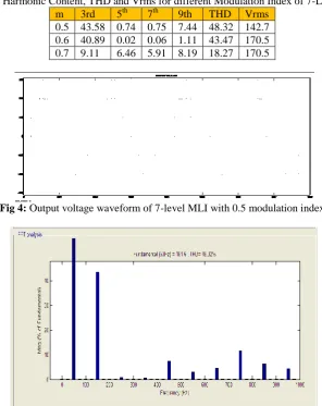
Table 2: Harmonic Content, THD and Vrms for different Modulation Index of 7-Level MLI
m 3rd 5th 7th 9th THD Vrms 0.5 43.58 0.74 0.75 7.44 48.32 142.7 0.6 40.89 0.02 0.06 1.11 43.47 170.5 0.7 9.11 6.46 5.91 8.19 18.27 170.5
Fig 4: Output voltage waveform of 7-level MLI with 0.5 modulation index
Fig 5: Harmonic content in Output voltage waveform of 7-level CHB-MLI with 0.5 modulation index
Figure 4,shows the output waveform of 7level CHM-MLI ,with particular modulation index ,i.e 0.5.Figure 5 shows the harmonic content in output voltage of 7 level CHB-MIL with 0.5 modulation index. It is observed that 5th, 7th and 9th is almost eliminated.
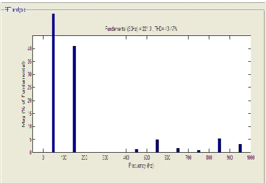
Fig 6: Output voltage waveform of 7-level MLI with 0.6 modulation index
Fig 7: Harmonic content in Output voltage waveform of 7-level CHB-MLI with 0.6 modulation index
Figure.7, shows the harmonic content in output voltage of 7 level CHB-MIL with 0.6 modulation index. It is observed that 5th, 7th and 9th is almost eliminated. It is observed that SHE technique successfully removes targeted harmonics from the output voltage waveform of the CHB-MLI. It can successfully calculate the angles where notches are required to remove the targeted harmonics.
VI.
CONCLUSION
The selective harmonic elimination strategy at fundamental has been solved using the proposed optimization technique that produces all possible solution sets of switching angles when they exist. In comparison with other methods, the proposed technique has many advantages such as: it can produce all possible solution sets for any numbers of multilevel inverter without much computational burden; convergencespeed is fast etc. The proposed technique was successfully implemented for computing the driving angles for7level H-Bridge cascaded multilevel inverter. It was observed that 5th ,7h and 9th harmonics were almost eliminated . A complete analysis for n - level inverter can be made and switching angle which results in lower THD and can be determined.
ACKNOWLEDGMENT
The authors are thankful to Don Bosco Institute of Technology for providing necessary facilities & support.
REFERENCES
[1]. F. Z. Peng, J. W. McKeever, and D. J. Adams, “Cascade Multilevel Inverters for Utility Applications”, IECON Proceedings (Industrial Electronics Conference), vol. 2, pp. 437-442, 1997
[2]. JaniRushiraj G. , Prof. P.N. Kapil “Analysis of Different Modulation Techniques for Multilevel Inverters", International Conference on Electrical, Electronics, and Optimization Techniques (ICEEOT) – 2016
[3]. Fang ZhengPeng, Jih-Sheng Lai, et al, “A Multilevel Voltage-Source Inverter with Separate DC Sources for Static Var Generation”, IEEE Trans. on Industry Applications, vol. 32, no. 5, pp. 1130-1138, September/October 1996.
[5]. L. M. Tolbert, F. Z. Peng, and T.G. Habetler, “Multilevel converters for large electric drives”, IEEE Transactions on Industry Applications, vol. 35, no. 1, pp. 36-44, Jan. /Feb. 1999.
[6]. R. Lund, M.D. Manjrekar, P. Steimer, T.A. Lipo, “Control strategies for a hybrid seven-level inverter”, in Proceedings of the European Power Electronic Conference , Lausanne, Switzerland, September 1990. [7]. John N. Chiasson, Leon M. Tolbert, Keith J. McKenzie, Zhong Du, “Control of a Multilevel Converter
Using Resultant Theory”, IEEE Transaction on Control Systems Technology, vol. 11, no. 3, pp. 345-353, May 2003.
[8]. John N. Chiasson, Leon M. Tolbert, Keith J. McKenzie, Zhong Du, “A new approach to solving the harmonic elimination equations for a multilevel converter”, in Proc. IEEE Industry Applications Soc. Annu. Meeting, Salt Lake City, UT, pp. 640-645, Oct.12-16, 2003.
[9]. BurakOzpineci, Leon M. Tolbert, John N. Chiasson, “Harmonic Optimization of Multilevel Converters Using Genetic Algorithms”, IEEE Power Electronics Letters, vol. 3, no. 3, pp.92-95, September 2005. [10]. C. Woodford and C. Phillips, “Numerical Methods with Worked Examples”, CHAPMAN & HALL, pp.
45-57, First edition 1997,
[11]. M. A. Kumar and S. Lakshminarayanan, "Cost effective gate drive circuit for MLI with constant number of conducting switches," 2016 IEEE International Conference on Recent Trends in Electronics, Information communication Technology (RTEICT), Bangalore, 2016, pp. 617- 622. doi: 10.1109/RTEICT.2016.7807896
[12]. Arun Kumar M, Sanjay Lakshminarayanan, “Evaluation of Different Multilevel Inverter topologies for Harmonics and Power Losses”,International Journal For Research in Applied Science and Engineering Technology, Vol 5, Issue XI, November 2017, pp 1369 - 1374.
AUTHORS
Meghana MC - Received B.E in Electrical and Electronics Engineering from B N M institute of
technology ,Bengaluru in the year 2013 and now currently pursuing M.Tech in Power System Engineering from DBIT, Bengaluru, Her academic interest area include. Power flow study, Optimization techniques, Renewable energy E-mail address: [email protected]
Dr W M Sivakumar- was ranked 7th in the state in Bachelors of Engineering (Electrical) from Karnataka University in 1979. He ranked 1st in Masters of Engineering (Power Systems) and secured the Gold Medal from University of Mysore in 1988. He completed his PhD on Artificial Intelligence Methodologies for Electric Distribution System Management functions from the University of Mysore in 2002. He has published 16 Technical Papers in International & National Journals. He was adjudged and awarded as the first ever Outstanding Engineer of Karnataka Electricity Board (KEB) in 1988. He was Managing Director of Karnataka VidyuthKarkhane Limited (KAVIKA), Government of Karnataka Undertaking. He is currently working as Professor in Don Bosco Institute of Technology. His research interests includes Switching in Power Systems; Integration renewable Energy Systems and Knowledge base Systems.E-mailaddress:[email protected]
Anguraja R – Received B.E in Electrical and Electronics Engineering from Bharathidasan University in the year 1996 and M.Tech in High Voltage Engineering from SASTRA University in the year 2004.He is pursuing Ph.D. in High Voltage Engineering. He is currently working as Associate Professor & Head of the Department in Don Bosco Institute of Technology. His research interests includes are Power System, Renewable Energy and High Voltage Engineering. E-mail address:[email protected].