Multi-Mode Analysis Software
SpectraMax
®Paradigm
®Multi-Mode Detection Platform
FilterMax™ Multi-Mode Microplate Readers
User Guide
5008530 A
September 2010
This document is provided to customers who have purchased Molecular Devices, Inc. (“Molecular Devices”) equipment, software, reagents, and consumables to use in the operation of such Molecular Devices equipment, software, reagents, and consumables. This document is copyright protected and any reproduction of this document, in whole or any part, is strictly prohibited, except as Molecular Devices may authorize in writing.
Software that may be described in this document is furnished under a license agreement. It is against the law to copy, modify, or distribute the software on any medium, except as specifically allowed in the license agreement. Furthermore, the license agreement may prohibit the software from being disassembled, reverse engineered, or decompiled for any purpose.
Portions of this document may make reference to other manufacturers and/or their products, which may contain parts whose names are registered as trademarks and/or function as trademarks of their respective owners. Any such usage is intended only to designate those manufacturers' products as supplied by Molecular Devices for incorporation into its equipment and does not imply any right and/or license to use or permit others to use such manufacturers' and/or their product names as trademarks.
Molecular Devices makes no warranties or representations as to the fitness of this equipment for any particular purpose and assumes no responsibility or contingent liability, including indirect or consequential damages, for any use to which the purchaser may put the equipment described herein, or for any adverse circumstances arising therefrom. For research use only. Not for use in diagnostic procedures.
Product manufactured by Molecular Devices, Inc.
1311 Orleans Drive, Sunnyvale, California, United States of America 94089. Molecular Devices, Inc. is ISO 9001 registered.
© 2010 Molecular Devices, Inc. All rights reserved.
Printed in Austria.
The trademarks mentioned herein are the property of Molecular Devices, Inc. or their respective owners. These trademarks may not be used in any type of promotion or advertising without the prior written permission of Molecular Devices, Inc.
ALPHASCREEN is a registered trademark of PerkinElmer, Inc. CHROMA-GLO is a trademark of Promega Corporation HTRF is a registered trademark of Cisbio Bioassays. BRET2 is a trademark of PerkinElmer, Inc.
Safety
Introduction
This section provides safety information and instructions for the hardware and accessories of the system. It includes the following topics:
• Safety Terminology on page 3
• Chemical and Biological Safety on page 5
• Electrical Safety on page 5
• Moving Parts on page 6
• Cleaning on page 6
• Disposal and Recycling on page 6
• Maintenance on page 7
• Warnings and Cautions Found in this User Guide on page 7
Safety Terminology
The symbols displayed below and on the instrument should remind you to read and understand all safety instructions before attempting installation,
operation, maintenance, or repair to this instrument.
CAUTION!Paragraphs marked by “CAUTION” indicate that there is a potential danger of equipment damage.
CAUTION!Paragraphs marked by “CAUTION” contain information about a possible software program failure, draw attention to a specific software setting or point out that a loss of data may occur if information stated within the paragraph is not adhered to or if procedures are executed incorrectly.
The symbols displayed below and on the instrument are reminders that all safety instructions should be read and understood before installation, operation, maintenance, or repair to this instrument is attempted.
WARNING! Paragraphs marked by “WARNING” alert you of a
potential hazard to your personal safety if you do not adhere to the information stated within the paragraph.
Note:Paragraphs marked by “Note” contain supplemental or explanatory information concerning the current topic or procedural step.
WARNING! When present, this symbol indicates that a potential hazard to your personal safety exists if information stated within the “WARNING” paragraph is not adhered to or procedures are executed incorrectly.
Safety
4 5008530 A
WARNING! This icon accompanies text and/or other symbols dealing with potential damage to equipment. When present, it indicates that there is a potential danger of equipment damage, software program failure, or that a loss of data may occur if information stated within the “CAUTION” paragraph is not adhered to or procedures are executed incorrectly.
WARNING! HIGH VOLTAGE Paragraphs marked by this symbol
indicate that a potential hazard to your personal safety exists from a high voltage source.
WARNING! BIOHAZARD Paragraphs marked by this symbol indicate that a potential hazard to your personal safety exists from a
biological source.
WARNING! LASER LIGHT Paragraphs marked by this symbol indicate that a potential hazard to your personal safety exists from a laser source.
WARNING! SHARP OBJECTS Paragraphs marked by this symbol indicate that a potential hazard to your personal safety exists from unblunted corners or other appendages on the outside or inside of the equipment.
WARNING! HOT SURFACE Paragraphs marked by this symbol indicate that a potential hazard to your personal safety exists from heated surfaces or other appendages on the outside or inside of the equipment.
WARNING! PROTECTIVE EARTH OR GROUND TERMINAL This symbol identifies the location of the protective earth or ground terminal lug on the equipment.
OFF POSITION OF PRINCIPAL POWER SWITCH This symbol graphically represents the equipment main power push-button switch when it is in the off position.
ON POSITION OF PRINCIPAL POWER SWITCH This symbol graphically represents the equipment main power push-button switch when it is in the on position.
Multi-Mode Analysis Software User Guide
Chemical and Biological Safety
Normal operation of the FilterMax 3 and FilterMax 5 Multi-Mode Microplate Readers and the SpectraMax Paradigm Multi-Mode Detection Platform may involve the use of materials that are toxic, flammable, or otherwise biologically harmful. When using such materials, observe the following precautions:
• Handle infectious samples according to good laboratory procedures and methods to prevent the spread of disease.
• Observe all cautionary information printed on the original solutions containers prior to their use.
• Dispose of all waste solutions according to your facility's waste disposal procedures.
• Operate the FilterMax 3 and FilterMax 5 Multi-Mode Microplate Reader, and the SpectraMax Paradigm Multi-Mode Detection Platform in
accordance with the instructions outlined in this user guide, and take all the necessary precautions when using pathological, toxic, or radioactive materials.
• Splashing of liquids may occur; therefore, take appropriate safety precautions, such as using safety glasses and wearing protective clothing, when working with potentially hazardous liquids.
• Use an appropriately contained environment when using hazardous materials.
• Observe the appropriate cautionary procedures as defined by your safety officer when using flammable solvents in or near a powered-up instrument.
• Observe the appropriate cautionary procedures as defined by your safety officer when using toxic, pathological, or radioactive materials.
Electrical Safety
To prevent electrically related injuries and property damage, properly inspect all electrical equipment prior to use and immediately report any electrical deficiencies. Contact a Molecular Devices Service Engineer for any servicing of equipment requiring the removal of covers or panels.
To reduce risk of electrical shock, all devices employ a three-wire electrical cable and plug to connect the equipment to earth ground.
• Ensure that the wall outlet receptacle is properly wired and earth grounded.
• DO NOT use a three-to-two wire plug adapter.
• DO NOT use a two-wire extension cord or a two-wire multiple-outlet power strip.
• Disconnect power to the system before performing maintenance.
• DO NOT remove any panels; panels should be removed only by qualified service personnel.
Note:Observe all warnings and cautions listed for any external devices attached or used during operation of the FilterMax 3 and FilterMax 5 Multi-Mode Microplate Readers and the SpectraMax Paradigm Multi-Multi-Mode Detection Platform. Refer to applicable external device user guides for operating
Safety
6 5008530 A
Moving Parts
To avoid injury due to moving parts, observe the following:
• Never attempt to exchange labware, reagents, or tools while the instrument is operating.
• Never attempt to physically restrict any of the moving components of the Multi-Mode Analysis Software.
• Keep the Multi-Mode Analysis Software work area clear to prevent obstruction of the movement.
Cleaning
Observe the cleaning procedures outlined in this user guide for the Multi-Mode Analysis Software. Prior to cleaning equipment that has been exposed to hazardous material:
• Appropriate Chemical and Biological Safety personnel should be contacted.
• The Chemical and Biological Safety information contained in this user guide should be reviewed.
Disposal and Recycling
The symbol of a crossed-out wheeled bin on the product is required in accordance with the Waste Electrical and Electronic Equipment (WEEE)
Directive of the European Union. The presence of this marking on the product indicates that the device:
• Was put on the European Market after August 13, 2005.
• Is not to be disposed via the municipal waste collection system of any member state of the European Union.
For products under the requirement of WEEE directive, please contact your dealer or local Molecular Devices office for the proper decontamination
information and take-back program, which will facilitate the proper collection, treatment, recovery, recycling, and safe disposal of the device.
WARNING! This symbol indicates the potential of an electrical shock hazard existing from a high voltage source and that all safety
instructions should be read and understood before proceeding with the installation, maintenance, and servicing of all modules.
Do not remove system covers. To avoid electrical shock, use supplied power cords only and connect to properly grounded (three-holed) wall outlets. Use only multiplug power strips provided by the manufacturer.
WARNING! It is important to understand and follow all laws
Multi-Mode Analysis Software User Guide
Maintenance
Perform only the maintenance described in this user guide. Maintenance other than that specified in this user guide should be performed only by service engineers.
Warnings and Cautions Found in this User Guide
Please read and observe all cautions and instructions. Remember, the most important key to safety is to operate the FilterMax 3 and FilterMax 5
Multi-Mode Microplate Reader and the SpectraMax Paradigm Multi-Mode Detection Platform with care.
The WARNINGs and CAUTIONs found within this document are listed below.
CAUTION!Settings that vary from the recommended Power Options Properties may introduce a risk of data transfer interruption and a loss of data.
CAUTION!In any situation (such as when operating the instrument with integrated systems) where automatic loading and ejection of the cartridge carrier may cause a potential equipment collision, we recommend disabling the Automatically load/eject cartridge carrier when running the Validation Plate feature, and to load and eject the cartridge carrier manually.
CAUTION!Shake low density plates, such as 6-well or 48-well plates, at low speed only. Shaking low density plates at higher speeds may cause liquid in wells to spill.
CAUTION!The plate height configured must not be less than that of the actual plate. Doing so may cause the FilterMax Multi-Mode Microplate Readers to collide with the plate during a Read Height Optimization. The SpectraMax Paradigm Multi-Mode Detection Platform has an auto-detection to prevent collision, if an incorrect plate height is entered for the SpectraMax Paradigm Multi-Mode Detection Platform an error message appears while running protocols using the defined labware.
CAUTION!Luminescence light levels visible to the human eye may cause damage to the detection system.
WARNING! It is your responsibility to decontaminate components of the Multi-Mode Analysis Software before requesting service by a Molecular Devices Service Engineer or returning parts to Molecular Devices for repair. Molecular Devices will NOT accept any items which have not been decontaminated where it is appropriate to do so. If any parts are retuned, they must be enclosed in a sealed bag stating that the contents are safe to handle and are not contaminated.
WARNING! If the equipment is used in a manner not specified by Molecular Devices, the protection provided by the equipment may be impaired.
Safety
Contents
Safety . . . 3
Introduction . . . 3
Safety Terminology . . . 3
Chemical and Biological Safety . . . 5
Electrical Safety . . . 5
Moving Parts. . . 6
Cleaning. . . 6
Disposal and Recycling. . . 6
Maintenance . . . 7
Warnings and Cautions Found in this User Guide. . . 7
Chapter 1 Overview . . . 15
Introduction . . . 15
Where to Begin . . . 15
Chapter 2 Installing, Using, and Configuring
the Software . . . 17
Overview . . . 17
Installing Multi-Mode Analysis Software . . . 17
Preparing to Install Multi-Mode Analysis Software . . . 17
Meeting System Requirements . . . 18
Upgrading From Previous Versions of the Software . . . 19
Installing Multi-Mode Analysis Software on Windows XP . . . 19
Installing Required Components and
Multi-Mode Analysis Software . . . 20
Installing the Required Multi-Mode System Updater . . . 22
Repairing or Removing the Multi-Mode Analysis
Software Installation . . . 24
Using Multi-Mode Analysis Software. . . 24
Launching the Software . . . 25
Using the Software Interface . . . 26
About the Navigation Pane . . . 26
About the Tool Bar. . . 27
About the Selection and Configuration Pane . . . 31
About the Preview Pane . . . 31
Accessing Online Help . . . 31
Configuring Multi-Mode Analysis Software . . . 32
Configuring Instrument Settings . . . 33
Configuring Software Settings. . . 35
Selecting Simulated Data Files . . . 35
Selecting a Directory for Saving Exported
Measurement Results . . . 37
Configuring Print Settings . . . 38
Contents
10 5008530 A
Configuring the Data Format . . . 43
Configuring Database Settings . . . 47
Deleting and Restoring Items . . . 48
Chapter 3 Configuring and Controlling Instruments . . . 51
Overview . . . 51
Managing Instruments . . . 52
Adding a New Instrument . . . 52
Deleting an Instrument. . . 53
Configuring the Current Instrument . . . 54
Controlling Instrument Actions . . . 54
Connecting to the Instrument . . . 55
Ejecting the Plate Carrier . . . 55
Loading the Plate Carrier. . . 55
Initializing the Instrument. . . 56
Enabling Simulation Mode . . . 56
Configuring the FilterMax Multi-Mode Microplate Readers
Instrument Settings . . . 57
Modifying and Viewing System Information . . . 58
Defining and Editing Filter Slides . . . 58
Adding Filter Slides. . . 59
Configuring Filter Slides . . . 60
Removing Filter Slides . . . 61
Exporting and Importing All Filter Slide Configurations . . . 61
Exporting and Importing Single Filter Slide Configurations . . . 61
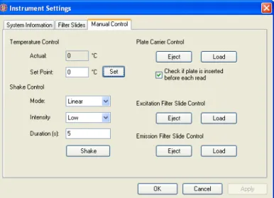
Manually Controlling the FilterMax Multi-Mode
Microplate Readers. . . 62
Temperature Control (FilterMax 5 Multi-Mode
Microplate Reader only) . . . 63
Shake Control . . . 63
Plate Carrier Control . . . 64
Excitation Filter and Emission Filter Slide Control . . . 64
Configuring SpectraMax Paradigm Multi-Mode
Detection Platform Instrument Settings . . . 64
Configuring SpectraMax Paradigm Multi-Mode
Detection Platform System Information Settings . . . 65
Viewing Installed Detection Cartridges . . . 66
Defining and Editing the Available Detection Cartridges . . . 66
Adding Detection Cartridges to the list of Available
Detection Cartridges. . . 67
Removing Detection Cartridges from the list of
Available Detection Cartridges . . . 68
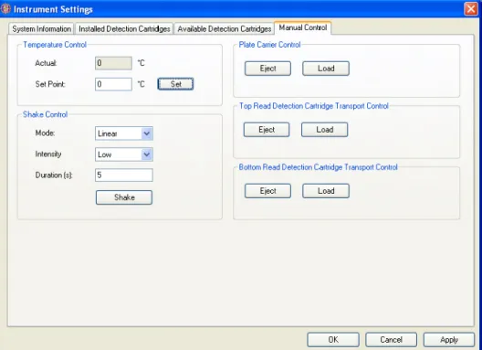
Manually Controlling the SpectraMax Paradigm Multi-Mode
Detection Platform Instrument. . . 69
Temperature Control . . . 70
Shake Control . . . 70
Plate Control . . . 71
Top Read Detection Cartridge Transport Control . . . 71
Multi-Mode Analysis Software User Guide
Chapter 4 Setting Up and Using GxP Permissions . . . 73
Overview . . . 73
Enabling GxP Permissions. . . 73
Performing System Administration Tasks . . . 75
Administering User Accounts and Roles . . . 75
Configuring Roles for Multi-Mode Analysis Software
User Accounts . . . 76
Restoring the Administrator Password . . . 79
Viewing the System Activity Audit Log . . . 79
Performing GxP Permissions User Actions in
Multi-Mode Analysis Software . . . 80
Logging On and Off the System. . . 81
Changing the Current User Password . . . 82
Viewing and Searching the Multi-Mode Analysis
Software Audit Log . . . 83
Reactivating Disabled Message Boxes . . . 83
Adding Electronic Signatures and Comments to Items . . . 84
Signing Items . . . 85
Viewing or Unlocking Signatures for an Item. . . 85
Viewing Unlocked Signatures . . . 86
Chapter 5 Creating and Editing Detection Methods . . . 87
Overview . . . 87
Viewing Available Detection Methods . . . 87
Creating Detection Methods (FilterMax Multi-Mode
Microplate Readers). . . 88
Selecting a Method Technique (FilterMax
Multi-Mode Microplate Readers) . . . 89
Selecting the Method Type (FilterMax
Multi-Mode Microplate Readers) . . . 90
Defining Method Parameters (FilterMax
Multi-Mode Microplate Readers) . . . 91
Defining Absorbance Method Parameters . . . 91
Defining Luminescence Method Parameters . . . 92
Defining Fluorescence Intensity Top Method Parameters . . . . 93
Defining Fluorescence Intensity Bottom Method Parameters
(FilterMax 5 Multi-Mode Microplate Reader only) . . . 95
Defining Fluorescence Polarization Method Parameters
(FilterMax 5 Multi-Mode Microplate Reader only) . . . 96
Defining Time-Resolved Fluorescence Method Parameters
(FilterMax 5 Multi-Mode Microplate Reader only) . . . 97
Signing a Detection Method (FilterMax
Multi-Mode Microplate Readers) . . . 98
Creating Detection Methods (SpectraMax Paradigm
Multi-Mode Detection Platform). . . 99
Selecting a Detection Cartridge (SpectraMax Paradigm
Multi-Mode Detection Platform) . . . 100
Absorbance (ABS) Detection Cartridge . . . 101
Contents
12 5008530 A
Multi-Mode (MULTI) Detection Cartridge . . . 104
Fluorescence Intensity (FI) Detection Cartridge . . . 109
Fluorescence Intensity Dual Label (FI-DL)
(MultiTox-Fluor) Detection Cartridge. . . 110
Time Resolved Fluorescence (TRF) Detection Cartridge . . . 112
Cisbio HTRF
®Detection Cartridge. . . 116
Luminescence (LUM) Detection Cartridge . . . 118
AlphaScreen Detection Cartridge . . . 121
Signing a Detection Method (SpectraMax Paradigm
Multi-Mode Detection Platform) . . . 122
Editing Detection Methods. . . 123
Copying Detection Methods . . . 124
Deleting Detection Methods. . . 124
Exporting and Importing Detection Methods . . . 125
Chapter 6 Creating and Editing Labware . . . 127
Overview . . . 127
Creating Labware. . . 128
Defining Labware Information . . . 129
General Labware Selection Guidelines. . . 131
Configuring Offsets and Well Dimensions for
the Default Labware Lot . . . 131
Signing Labware . . . 133
Editing Labware . . . 133
Viewing and Editing Labware Information . . . 134
Selecting and Editing Labware Lots . . . 135
Copying Labware . . . 136
Deleting Labware . . . 136
Optimizing Labware . . . 137
Creating a Copy of the Labware to be Optimized . . . 138
Start the Optimization Wizard . . . 138
Selecting the Detection Method . . . 138
Preparing and Loading the Labware . . . 139
Performing the Optimization Read . . . 140
Selecting the Centers of the Four Corner Wells . . . 141
Verifying Well Centers . . . 142
Exporting and Importing Labware . . . 143
Chapter 7 Creating and Running Protocols . . . 145
Overview . . . 145
Creating Protocols . . . 146
Configuring General Settings . . . 148
Selecting the Technique Type . . . 149
Selecting the Labware Type Used in the Protocol . . . 150
Configuring Labware Layout Settings . . . 151
Configuring Dilution Factors . . . 154
Adding Detection and Preparation Methods
for Analysis Protocols . . . 155
Configuring Method Properties . . . 159
Multi-Mode Analysis Software User Guide
Determining the Normalization Factor . . . 169
Configuring Variables . . . 170
Configuring the Data Reduction. . . 172
Configuring a Transformation Formula . . . 177
Configuring Concentration . . . 179
Configuring Cutoff Values . . . 183
Configuring Validation Rules . . . 185
Configuring Output Settings . . . 187
User Defined Excel Export. . . 189
Workbook Export Options . . . 190
Worksheet Export Options . . . 191
New Sheet and Existing Sheet Export Options . . . 192
Exporting Measurement Data to SoftMax Pro Software . . . 193
Exporting Data to SoftMax Pro File Format . . . 193
Starting SoftMax Pro Software and Importing Data . . . 194
Configuring a Program to Execute after
a Protocol Run Completes . . . 195
Signing a Protocol . . . 196
Creating a Protocol from a Template . . . 196
Running Protocols . . . 197
Running a Protocol on an Instrument . . . 197
Optimizing Read Height (FilterMax 5 Multi-Mode
Microplate Reader). . . 200
Optimizing Read Height (SpectraMax Paradigm
Multi-Mode Detection Platform) . . . 203
Viewing the Run Protocol Runtime Display . . . 206
Running a Protocol When Simulation Mode is Enabled . . . 209
Editing Protocols . . . 211
Copying Protocols . . . 212
Deleting Protocols . . . 212
Printing Protocol Configuration Information . . . 213
Exporting and Importing Protocols. . . 214
Chapter 8 Viewing Measurement Results . . . 215
Overview . . . 215
Viewing Measurement Results in the Result Viewer . . . 217
Viewing Raw Data . . . 218
Viewing Blanked Data . . . 219
Viewing Reduced Data . . . 221
Viewing Mean Data . . . 223
Viewing Graphs . . . 224
Viewing Two-Dimensional Graphs . . . 225
Viewing Three-Dimensional Graphs . . . 226
Recalculating Data Reduction . . . 227
Exporting Measurement Results to Microsoft Excel. . . 228
Saving Measurement Results . . . 228
Viewing and Reevaluating Results from an
Analysis Application . . . 229
Viewing Results From an Analysis Protocol . . . 230
Contents
14 5008530 A
Reevaluating Results from an Analysis Protocol . . . 233
Viewing Exported Measurement Results . . . 235
Viewing Measurement Results in Microsoft Excel . . . 235
Viewing Protocol and Measurement Information. . . 236
Viewing Raw Data . . . 237
Viewing Reduced and Transformed Data . . . 237
Signing Measurement Results . . . 238
Deleting Measurement Results. . . 239
Printing Measurement Results . . . 239
Appendix A Data Reduction Techniques . . . 241
Supported Data Reduction Techniques . . . 241
Appendix B PathCheck® Pathlength Measurement
Technology . . . 245
Overview . . . 245
Using the PathCheck Pathlength Measurement Technology
Water Constant . . . 246
Background Constant Subtraction and Blanking
Considerations. . . 247
Use Plate Background Constant . . . 247
PathCheck Pathlength Measurement Technology and
Interfering Substances . . . 247
Determining Color Interference . . . 248
Appendix C Mathematical Operators and Functions . . . 249
1
Overview
Introduction
Multi-Mode Analysis Software configures and controls all measurement protocols and actions performed by the FilterMax Multi-Mode Microplate Readers and the SpectraMax Paradigm Multi-Mode Detection Platform. The software supports detection for absorbance, glow luminescence, fluorescence intensity, fluorescence polarization, and time-resolved fluorescence (TRF) measurements including HTRF. The measurement methods available to users depend on the capabilities of the instrument being controlled. Measurement results can be viewed in the Multi-Mode Analysis Software or easily exported to compatible applications such as Microsoft Excel.
Optional modules such as GxP Permissions lend support for electronic signature regulations such as 21 CFR Part 11.
This user guide covers the functionality supplied by the Multi-Mode Analysis Software and the Multi-Mode Analysis Software with GxP Permissions modules, including:
• Configuring and Controlling Instruments on page 51
• Setting Up and Using GxP Permissions on page 73
• Creating and Editing Detection Methods on page 87
• Creating and Editing Labware on page 127
• Creating and Running Protocols on page 145
• Viewing Measurement Results on page 215
Where to Begin
To correctly use the software it is important that initial configuration is done in a specific order.
1. Installing Multi-Mode Analysis Software on page 17.
2. Configuring Multi-Mode Analysis Software on page 32.
3. Configuring and Controlling Instruments on page 51.
4. Setting Up and Using GxP Permissions on page 73 (optional module).
5. Creating Detection Methods (FilterMax Multi-Mode Microplate Readers) on page 88 or Creating Detection Methods (SpectraMax Paradigm Multi-Mode Detection Platform) on page 99. The measurement configuration parameters are stored in detection methods.
6. Creating and Editing Labware on page 127. Labware types must be configured and ready for use in protocols.
7. Creating Protocols on page 146 using the detection methods created in
Step 5. A protocol stores all parameters required to perform a
measurement, including technique types, detection methods, labware types, and preparation methods, such as shaking.
8. Running Protocols on page 197.
9. Viewing Measurement Results on page 215.
10.When required, create additional detection methods, labware, and protocols.
Overview
2
Installing, Using, and Configuring
the Software
Overview
This section introduces users to the software and gives the instructions for:
• Installing Multi-Mode Analysis Software on page 17
• Using Multi-Mode Analysis Software on page 24
• Configuring Multi-Mode Analysis Software on page 32
• Deleting and Restoring Items on page 48
Installing Multi-Mode Analysis Software
The Multi-Mode Analysis Software installer provides the ability to install the software onto a new system or update from a previous version of the software. Installing the software requires:
• Preparing to Install Multi-Mode Analysis Software on page 17
• Meeting System Requirements on page 18
• Installing Multi-Mode Analysis Software on Windows XP on page 19
Preparing to Install Multi-Mode Analysis Software
Before installing Multi-Mode Analysis Software, confirm that the host computer meets the minimum system requirements listed in Meeting System
Requirements on page 18.
If upgrading from previous versions of Multi-Mode Analysis Software, see
Upgrading From Previous Versions of the Software on page 19 before installing. The information in this section helps to ensure the update is successful.
Installing, Using, and Configuring the Software
18 5008530 A
Meeting System Requirements
To install and use the software successfully, the host computer must meet the minimum system requirements listed in Table 2-1. Where relevant, Table 2-1
also lists recommended specifications.
Table 2-1Host Computer System Requirements
Component Minimum System Requirements
CPU Pentium III 600 Mhz
RAM 256 MB minimum
512 MB or more recommended
Hard Drive 600 MB free space
CD-ROM Drive 4X
Monitor 800x600 resolution
Keyboard 101 key
Mouse IBM compatible
Serial Port
USB Port 1 free serial port or 1 free USB port
Operating System Microsoft Windows XP (Service Pack 2) Operating System
Language English (U.S.)
Database Microsoft SQL Server 2000 (Desktop Edition included on the
installation CD)
Note:SQL Server 2000 Desktop Edition has a 2GB storage limit. Contact Molecular Devices Technical Support if this limit is reached.
Web Browser Microsoft Internet Explorer 6.0 or later (included on the installation CD)
Programs Microsoft Excel 2003 recommended
Power Options
Properties Turn off hard disks: NeverSystem standby: Never System hibernates: Never
Note:System power options properties are set in Control Panel > Power Options.
CAUTION!Settings that vary from the recommended Power Options Properties can introduce a risk of data transfer interruption and a loss of data.
Multi-Mode Analysis Software User Guide
Upgrading From Previous Versions of the Software
If upgrading from a previous Multi-Mode Analysis Software version, follow the steps in this section to make sure that the update is successful.
To update the software from a previous version:
1. Launch Multi-Mode Analysis Software and open Instrument Settings.
2. For FilterMax instruments: If the filter slides have been customized by installing new filters or moving existing filters to other slots, these settings need to be saved and later imported after software installation. In Instrument Settings, select the Filter Slides tab and select Export Slides before proceeding with installation. See Exporting and Importing All Filter Slide Configurations on page 61.
3. Install the software by following the steps in Installing Multi-Mode Analysis Software on page 17.
4. When the installation is complete, launch Multi-Mode Analysis Software. The software automatically checks if any default detection methods, labware types, and protocols provided with the install have the same name as those imported to the database from the previous versions.
Installing Multi-Mode Analysis Software on Windows XP
On a Windows XP system, the Multi-Mode Analysis Software installer uses a simple interface to guide the installation using the two CDs provided with your purchase. Installation proceeds in two phases:
• Installing Required Components and Multi-Mode Analysis Software on page 20
• Installing the Required Multi-Mode System Updater on page 22
Note:Installing a newer version of Multi-Mode Analysis Software replaces the previous version.
Note:If a prompt appears asking whether a detection method, labware type, or protocol should be overwritten, click Yes to overwrite the existing item or click No to keep the existing item in the database.
Note:SpectraMax Paradigm Multi-Mode Detection Platform: For each new detected cartridge, example Protocols and Methods are imported automatically. The automatic importing function may be disabled. To do this, go to the Multi-Mode Analysis Software main window. Then from the File menu click Settings > Properties > Allow Protocol Auto-Import.
Installing, Using, and Configuring the Software
20 5008530 A
Installing Required Components and
Multi-Mode Analysis Software
To install the components and software:
1. Exit all Windows programs before starting installation.
2. Ensure the current user account has Administrator privileges. Accounts with Standard or Restricted access are not allowed to run the setup program. Contact the site system administrator for more information about account privileges.
3. Insert the installation CD 1 into the CD drive and browse to the contents of the CD.
4. Double-click on Installer.exe. The Multi-Mode Analysis Software Installer appears Figure 2-1. All components required to successfully install the software are listed along with the current status of each component:
A check icon indicates the correct version of the component is already installed on the system.
A caution icon indicates that an older version of the component is installed and must be updated before the software can be installed.
An X icon indicates that the component must be installed before the Multi-Mode Analysis Software can be installed.
Figure 2-1Starting the Installation
5. Select Update or Install for the first component indicated. The components are installed one at a time and must be installed in the order listed.
6. Follow the steps in the component installer until the component
installation is complete. Restart the system as required. For example, a restart might required after the Microsoft SQL Server installation.
Note:If a component installation requires restarting the system, restart before installing the next component listed. After the system restarts, browse to the contents of the installer CD and launch the installer again to continue installing components.
Multi-Mode Analysis Software User Guide
7. Repeat Step 5 and Step 6 for each component required.
When all components are installed correctly, the Install Multi-Mode Software button launches the Multi-Mode Analysis Software System Updater.
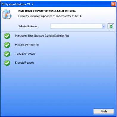
8. Click Install Multi-Mode Software to launch the Multi-Mode System Updater.
Figure 2-2System Updater Window
9. Follow the steps as described in Installing the Required Multi-Mode System Updater on page 22.
10.In the Multi-Mode Analysis Software Installer, click Finish.
CAUTION!Settings that vary from the recommended Power Options Properties may introduce a risk of data transfer interruption and a loss of data.
11.Open the Power Options Properties by selecting Start > Control Panel > Power Options.
12.Set Turn off Hard Disks to Never.
13.Set System standby to Never.
14.Set System hibernates to Never. The software is ready for use.
Note:Some components can give the option to Repair or Remove the component. First click Remove to remove the component and then click Install to reinstall the component.
Installing, Using, and Configuring the Software
22 5008530 A
Installing the Required Multi-Mode System Updater
Upon installing, reinstalling, or updating Multi-Mode Analysis Software from a previous version, running the System Updater will provide vital updates to firmware, detection cartridge files and other components specific to your instrument’s needs.
To run the System Updater:
1. If installing the Multi-Mode System Updater as a part of the Multi-Mode Analysis Software installation, remove installation CD 1 from the CD drive and insert CD 2 into the CD drive.
If installing the System Updater separately, exit all Windows programs before starting system update as shown in Installing the Required Multi-Mode System Updater on page 22. Insert CD 2 into the CD drive and browse to the contents of the CD. Double click installer.exe
The System Updater window appears Figure2.3.
Figure 2-3System Updater Window
Note:If new detection platform products are purchased (such as SpectraMax Paradigm detection cartridges), or you intend to update your Multi-Mode Analysis Software installation, it is recommended that you use the Multi-Mode System Updater CD Package to consistently update your system.
Note:SpectraMax Paradigm Multi-Mode Detection Platform: Ensure the instrument is turned on, not in the standby mode, and all your detection cartridges are installed.
Multi-Mode Analysis Software User Guide
2. Click the Install or Update links to add components as required by the System Updater.
3. When finished, the System updater window appears Figure 2-4.
Figure 2-4System Updater Window Showing Fully Updated Controller PC System
4. Upon completion of the entire update process, click Finish. The Multi-Mode Software Installer window appears.
5. Click Finish.
The software is ready for use.
Note:Depending on the host system’s firewall configuration, a
Windows firewall message might request that you unblock Multi-Mode System Updater’s executable file, SystemUpdater.exe. If this message does show, allow unblocking.
Note:During the install/update process, the instrument might initialize and produce sounds while the System Updater runs.
Note:If the System Updater ran as a part of the Multi-Mode Analysis Software installation, click Finish to close that installation also.
Installing, Using, and Configuring the Software
24 5008530 A
Repairing or Removing the Multi-Mode Analysis
Software Installation
In the event required components are missing or damaged, or if the software does not open or does not run correctly, repair should be made by uninstalling the Multi-Mode Analysis Software from the controlling PC system.
To repair or remove the software:
1. Exit all open Windows programs.
2. Make sure the current user account has Administrator privileges. Accounts with Standard or Restricted access are not permitted to modify or remove software. Contact the site system administrator for more information about account privileges.
3. If repairing the installation, insert the Multi-Mode Analysis Software installation CD into the CD-ROM drive.
4. From the Start menu, click Settings > Control Panel. The Control Panel
appears.
5. In Control Panel, double-click Add or Remove Programs. The Windows
Add or Remove Programs dialog appears.
6. In the Add or Remove Programs dialog, select Multi-Mode Analysis
Software. Repair and removal options for Multi-Mode Analysis Software appear.
7. Click Remove and follow the instructions until the removal process is completed. Proceed to step 8.
8. When finished, reinstall Multi-Mode Analysis Software from the original installation CD.
Using Multi-Mode Analysis Software
The Multi-Mode Analysis Software uses a simple interface that divides the main window into four basic sections: navigation pane, tool bar, selection and configuration pane, and preview pane (Figure2.5). The interface provides access to the selection lists that enables system functionality and
comprehensive, context-sensitive online help. This section covers:
• Launching the Software on page 25
• Using the Software Interface on page 26
• Accessing Online Help on page 31
Note:When removing the software, only files installed during the initial installation are removed. The software database and files created after the installation, such as exported measurement results, remain.
Note:To correctly use the software it is important that the initial configuration is done in a particular order. Please see Where to Begin regarding important setup information.
Multi-Mode Analysis Software User Guide
Launching the Software
To launch Multi-Mode Analysis Software:
• From the Windows Start menu, click Programs > Molecular Devices > Multi-Mode Analysis Software> Multi-Mode Analysis Software. The Multi-Mode Analysis Software window appears (Figure 2-5).
Figure 2-5Multi-Mode Analysis Software Main Window
Note:If the Multi-Mode Analysis Software is not found in the Start menu, the software may have been installed for a single user account on the system instead of all accounts. Check with the site system administrator or login to the user account with permission to access the software. See Installing Multi-Mode Analysis Software on Windows XP on page 19 for more information about installing the software for a single or multiple user accounts.
Note:The first time the software is launched, depending on the host system’s firewall configuration, a Windows firewall message might request that you unblock Multi-Mode Analysis Software’s executable file, Apex.exe. If this message does show, allow unblocking.
Installing, Using, and Configuring the Software
26 5008530 A
Using the Software Interface
Multi-Mode Analysis Software uses a simple interface that is divided into four basic sections:
• Navigation Pane (See About the Navigation Pane on page 26)
• Tool Bar (See About the Tool Bar on page 27)
• Selection and Configuration Pane (See About the Selection and Configuration Pane on page 31)
• Preview Pane (See About the Preview Pane on page 31)
The navigation pane provides access to the selection lists that provide the majority of the functionality built into the software. Items selected in the selection list determine the options available in the tool bar and configuration pane.
About the Navigation Pane
The navigation pane is the narrow pane on the left of the Multi-Mode Analysis Software window (Figure 2-5). Use the navigation pane to switch between selection lists.
Table 2-2The Navigation Pane
Name Button Description
Protocols Contains the Protocols Selection List
and provides the ability to define, run, edit, copy, delete, and print measurement protocols. See Creating and Running Protocols. A protocol stores all parameters required to perform a measurement, including technique types, detection methods, labware types, and preparation methods such as shaking.
Detection Methods Contains the Detection Method
Selection List and provides the ability to create, edit, copy, and delete detection methods. See Creating and Editing Detection Methods.
Measurement configuration
parameters are stored in detection methods.
Results Contains the Results Selection List
and provides the ability to view saved measurement results and modify data reduction parameters in the Result Viewer. Measurement results may be reevaluated using parameters different from those configured in the original protocol. See Viewing Measurement Results. Measurement results from each protocol run are stored in the Multi-Mode Analysis Software database and are accessed only from the Results Selection List.
Labware Contains the Labware Selection List
and provides the ability to create, edit, optimize, copy, and delete labware types. See Creating and Editing Labware.
Multi-Mode Analysis Software User Guide
About the Tool Bar
The tool bar provides easy access to common software actions. The module chosen in the navigation pane determines which actions are available on the tool bar; for example, Optimize Labware is only available when the Labware module is active. A description of each tool bar is included for each view:
• Protocols Selection List Tool Bar. See Table 2-3.
• Detection Method Selection List Tool Bar. See Table 2-4.
• Results Selection List Tool Bar. See Table 2-5.
• Labware Selection List Tool Bar. See Table 2-6.
• Instrument Selection List Tool Bar. See Table 2-7.
• Users Tool Bar. See Table 2-8.
• Trash Tool Bar. See Table 2-9.
The Protocols Selection List tool bar provides access for creating, editing, and running protocols. A protocol stores all parameters required to perform a measurement, including technique types, detection methods, labware types, and preparation methods, such as shaking.
Instruments Contains the Instrument Selection
List and provides the ability to manually control instrument actions (such as shaking, or loading and ejecting the plate carrier) and configure instrument settings and filter slides or detection cartridges. See Configuring and Controlling Instruments. The active instrument is controlled using the Instrument Selection List.
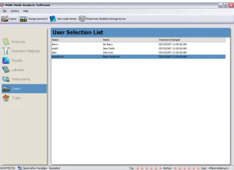
Users Appears in the navigation pane only
when the Multi-Mode Analysis Software with GxP Permissions module is installed and enabled on the system. GxP Permissions is an integrated set of features that help Multi-Mode Analysis Software users comply with electronic signature regulations, such as 21 CFR Part 11. See Performing GxP Permissions User Actions in Multi-Mode Analysis Software on page 80.
Trash Contains the Trash List containing
labware, detection methods, and protocols pending deletion. This section provides the ability to restore or permanently delete items from the database. See Deleting and Restoring Items on page 48.
Table 2-2The Navigation Pane (cont’d)
Installing, Using, and Configuring the Software
28 5008530 A
The Detection Method Selection List tool bar provides access for creating and editing detection methods. Measurement configuration parameters are stored in detection methods.
Table 2-3Protocols Selection List Tool Bar
Button Description
Creates a new protocol, see Creating Protocols on page 146.
Runs the currently selected protocol, see Running Protocols on page 197.
Edits the currently selected protocol, see Editing Protocols on page 211.
Copies the currently selected protocol, see Copying Protocols on page 212.
Prints the configuration information for the currently selected protocol, see Printing Protocol Configuration Information on page 213.
Deletes the currently selected protocol, see Deleting Protocols on page 212.
Table 2-4Detection Method Selection List Tool Bar
Button Description
Creates a new detection method, see Creating Detection Methods (FilterMax Multi-Mode Microplate Readers) on page 88 or Creating Detection Methods (SpectraMax Paradigm Multi-Mode Detection Platform) on page 99.
Edits the currently selected detection method, see Editing Detection Methods on page 123.
Copies the currently selected detection method, see Copying Detection Methods on page 124.
Deletes the currently selected detection method, see Deleting Detection Methods on page 124.
Multi-Mode Analysis Software User Guide
The Results Selection List tool bar provides access to viewing, printing, and deleting results. Measurement results from each protocol run are stored in the Multi-Mode Analysis Software database and are accessed only from the Results Selection List.
The Labware Selection List tool bar provides access to creating, copying, optimizing, and deleting labware.
Table 2-5Results Selection List Tool Bar
Button Description
Deletes all displayed results, see Deleting Measurement Results on page 239.
Deletes currently selected result, see Deleting Measurement Results on page 239.
Views the currently selected result, see Viewing Measurement Results in the Result Viewer on page 217.
Prints the currently selected result, see Printing Measurement Results on page 239
Table 2-6Labware Selection List Tool Bar
Button Description
Creates a new labware type, see Creating Labware on page 128.
Edits the currently selected labware type, see Editing Labware on page 133.
Copies the currently selected labware type, see Copying Labware on page 136.
Optimizes the currently selected labware type, see Optimizing Labware on page 137.
Deletes the currently selected labware type, see Deleting Labware on page 136.
Installing, Using, and Configuring the Software
30 5008530 A
The Instrument Selection List tool bar provides access to adding, deleting, configuring, managing, and connecting to an instrument.
The Users tool bar provides access to logging out the current user, changing the password, viewing the audit log, and reactivating disabled message boxes.
Table 2-7Instrument Selection List Tool Bar
Button Description
Adds a new instrument to the instrument selection list, see Adding a New Instrument on page 52.
Deletes the currently selected instrument, see Deleting an Instrument on page 53.
Sets the currently selected instrument to the current instrument, see
Configuring the Current Instrument on page 54.
Configures instrument settings, see Configuring the FilterMax Multi-Mode Microplate Readers Instrument Settings on page 57 or
Configuring SpectraMax Paradigm Multi-Mode Detection Platform System Information Settings on page 65.
Ejects the currently selected instrument’s plate carrier, see
Connecting to the Instrument on page 55.
Loads the currently selected instrument’s plate carrier, see Loading the Plate Carrier on page 55.
Initialize the currently selected instrument, see Initializing the Instrument on page 56.
Connects to the currently selected instrument, see Enabling Simulation Mode on page 56.
Table 2-8Users Tool Bar
Button Description
Logs out the current user, see Logging On and Off the System on page 81.
Changes the password of the user currently logged in, see Changing the Current User Password on page 82.
Views the audit log for the Multi-Mode Analysis Software, see Viewing and Searching the Multi-Mode Analysis Software Audit Log on page 83.
Reactivates disabled message boxes for the current user, see Reactivating Disabled Message Boxes on page 83.
Multi-Mode Analysis Software User Guide
The Trash tool bar provides access for permanently removing and restoring items pending deletion from the database.
About the Selection and Configuration Pane
The selection and configuration pane is the large pane to the right of the navigation pane. Options available in this pane change depending on which module is currently selected in the navigation pane. For example, when Protocols is selected, the Protocol Selection List is displayed, which provides access to configured protocols and functionality specific to the Protocols module.
About the Preview Pane
The preview pane appears below the selection and configuration pane. It contains additional information about the selected object in the Protocols, Detection Methods, Labware, or Instruments selection lists. For example, when an instrument is selected in the Instrument Selection List, the
parameters of the instrument appear in the preview pane. To hide the preview pane click Hide Preview. To display the preview pane click Show Preview.
Accessing Online Help
The Multi-Mode Analysis Software contains detailed online help that covers defining and editing labware, detection methods, and protocols, performing measurements, and exporting measurement results. The online help is context sensitive, which provides instant access to help for the active screen.
To access online help:
• Press F1 at any time to display online help for the active screen.
• From the Help menu, select Help > Contents to display the table of contents.
Table 2-9Trash Tool Bar
Button Description
Restores currently selected item, see Deleting and Restoring Items on page 48.
Restores all items in trash, see Deleting and Restoring Items on page 48.
Permanently removes the selected item from the database, see
Deleting and Restoring Items on page 48.
Permanently removes all items in trash from the database, see
Installing, Using, and Configuring the Software
32 5008530 A
Configuring Multi-Mode Analysis Software
After installing the software, physically connecting the instrument to a serial port on the host computer and turning the instrument on, instrument and software settings must be configured.
Configuration activities include:
• Configuring Instrument Settings on page 33
• Configuring Software Settings on page 35
To set up Multi-Mode Analysis Software:
1. From the Windows Start menu, select Programs > Molecular Devices > Multi-Mode Analysis Software > Multi-Mode Analysis Software. The Multi-Mode Analysis Software appears (Figure 2-6).
Figure 2-6Multi-Mode Analysis Software Main Screen
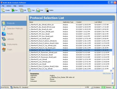
2. If the Protocol Selection List (Figure 2-6) appears immediately, the instrument was automatically detected by the software. Proceed to
Configuring Software Settings on page 35, to configure system settings.
OR
If a warning dialog appears (Figure 2-7), the instrument was not detected by the software. Click OK to work in simulation mode.
Note:If Multi-Mode Analysis Software is not found from the Windows
Start menu, the software may have been installed for a single user account on the system instead of for all accounts. Check with the site system administrator or log in to the user account with permission to access the software. See Using Multi-Mode Analysis Software on page 24 for more information about installing the software for a single or multiple user accounts.
Multi-Mode Analysis Software User Guide
Figure 2-7Warning Dialog Instrument Not Connected
Configuring Instrument Settings
Before an instrument is connected, a simulated instrument appears in the Instrument Selection List (Figure 2-8). When an actual instrument is detected by the software and has successfully connected, the simulated instrument is replaced in the list by the connected instrument.
Note:Upon establishing a physical connection from the controlling PC, in many cases Multi-Mode Analysis Software may automatically detect and initialize the instrument.
Note:If the instrument is not detected check to see that the instrument is turned on, the instrument is connected to the controlling PC on which the software is installed, and that the instrument LED is not flashing. After turning on or plugging in the instrument click Connect on the Instrument Selection List toolbar. If the instrument does not connect automatically contact your local Molecular Devices Field Service Representative.
Note:Upon software start up, the software will check if the instrument is locked, or is detected as a new instrument. If the software detects the instrument in either state, the unlock wizard will start up. Proceed to unlock the instrument before continuing.
Note:When GxP Permissions is enabled on the system, only users assigned a role containing the Instrument Settings permission may configure instrument settings. See Configuring Roles for Multi-Mode Analysis Software User
Installing, Using, and Configuring the Software
34 5008530 A
To configure instrument settings:
1. From the navigation pane, select Instruments. The Instrument Selection List appears (Figure 2-8).
Figure 2-8Instrument Selection List with Simulated Instrument Selected
2. From the tool bar, select Settings. OR
From the menu bar select Actions > Instrument Settings.
3. The Instrument Settings dialog appears (Figure 2-9).
Figure 2-9SpectraMax Paradigm Multi-Mode Detection Platform Instrument Settings
Multi-Mode Analysis Software User Guide
4. Select the System Information tab, if necessary.
5. In Instrument Name, modify the instrument’s name if desired.
6. Click OK to close the Instrument Settings dialog.
Configuring Software Settings
The Multi-Mode Analysis Software can be customized using the options available in Software Settings (Figure 2-10). Use the menu in Software Settings to configure print options, default simulated data files, and the directory where measurement results are stored.
To configure Software Settings:
1. Select File > Settings. The Software Settings window appears (Figure 2-10).
Figure 2-10Software Settings Window
2. Configure the settings using the menus:
Selecting Simulated Data Files
Selecting a Directory for Saving Exported Measurement Results
Configuring Print Settings
Configuring Properties
Configuring the Data Format
Configuring Database Settings
Selecting Simulated Data Files
Protocols may be run in simulation mode, which allows the protocol
configuration to be tested using simulated data before performing the protocol on actual samples. In simulation mode, all features for the instrument type currently selected in the Instrument Selection List are available, but
measurement results are either randomly generated by the software or read from a data file.
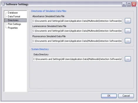
Use the Directories menu option to select the default data files for simulated absorbance, luminescence, and fluorescence measurements (Figure 2-11).
Installing, Using, and Configuring the Software
36 5008530 A
Figure 2-11Selecting the Simulated Data Files To select different simulated data files:
1. Select the Directories menu. The Simulated Data window appears (Figure 2-11).
2. In the desired field, enter the full path to the new simulated data file. For example: c:\detection software templates\DefaultSimulatedData.dat
Any data file with a .dat extension may be selected, including prior measurement results. Proceed to step 3.
OR
Click the browse (...) button next to the desired measurement type. The Open dialog appears.
3. In the Open dialog, browse to and select the desired data file. Any data file with a .dat extension may be selected, including prior measurement results.
4. Click the Open button to select the data file and return to the Software Settings tab.
5. Repeat steps 2 through 4 for each simulated data file, as desired.
6. Click OK to set the new default data files.
Note:Simulated data files are used when the number of measurement points in the simulated protocol run is the same as those present in the data file. When the number of measurement points is different, the software generates random data.
Multi-Mode Analysis Software User Guide
Selecting a Directory for Saving Exported
Measurement Results
Exported measurement results files, regardless of format, are saved into a single directory. The default storage directory is:
C:\Documents and Settings\All Users\Application Data\Multi-Mode\Detection Software\data
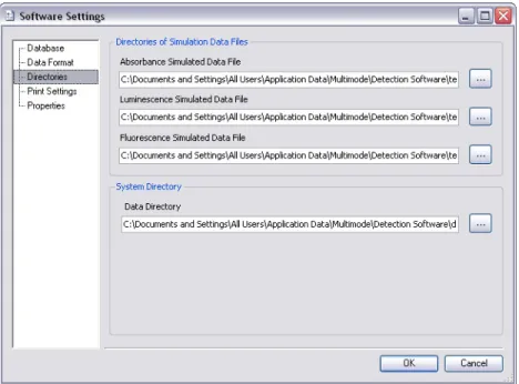
Use the Directories menu (Figure 2-12) to change the storage directory, as desired.
Figure 2-12Directories Window for Data Storage Locations To select a different storage directory:
1. Select the Directories menu. The directories window appears (Figure 2-12).
2. In the Data Directory path field, enter the complete path of the desired storage directory;
3. for example: C:\documents\Multi-Mode measurement results\MyResults\
OR
Click the browse (...) button for a directory and use the Open window to browse to and select the desired directory.
4. Click OK to set the new storage directory.
Note:All measurement results are also stored in the Multi-Mode Analysis Software database and may be accessed using the Result Viewer. See Viewing Measurement Results in the Result Viewer on page 217.
Installing, Using, and Configuring the Software
38 5008530 A
Configuring Print Settings
Measurement results and protocol configurations may be printed. Printing parameters, such as headers and footers are configured in the Print Settings window (Figure 2-13).
Figure 2-13Print Settings Window To configure print settings:
1. Select the Print Settings menu. The Print Settings window appears (Figure 2-13).
2. In the Print Header section, enter text for each header line, as desired. Header lines may be left blank.
3. In the Footer section, enter text for the Footer and Comment, as desired. The comment will display on printed pages below the footer. The footer and comment may be left blank.
4. In the Print Options section, select Print Preview to preview the page layout each time a protocol configuration or measurement results are printed.
5. In the Print Options section, select Show printer settings to display printing options each time a protocol or measurement results are printed.
6. In the Print Options section, select the desired Font and Font Size for printed text.
Multi-Mode Analysis Software User Guide
Configuring Properties
Certain settings (described below) may be configured from the Properties
window.
1. In the Software Settings window, select the Properties menu. The List View Settings and some other general settings appear (Figure 2-14).
Figure 2-14Software Settings Window
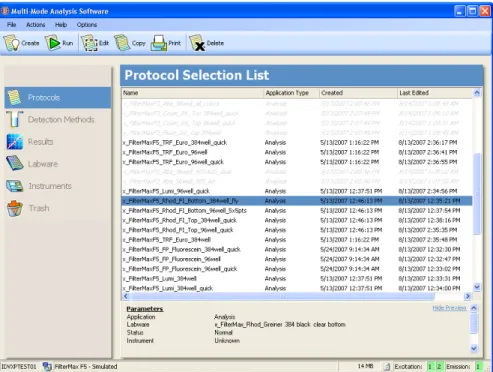
2. Select Show all Methods and Protocols in list view to display all methods and protocols on the Protocol Selection List window. Those protocols not available will be grayed out (Figure 2-15). When deselected unavailable methods and protocols are not displayed at all (Figure 2-16).
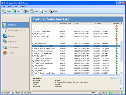
3. Select Show enabled state icon in list view for methods and protocols to display an enabled column in the Detection Methods List view and the Protocols Selection list view (Figure 2-17 and Figure 2-18). This allows the user to easily view if the detection method or protocol is currently enabled.
4. Select Allow Protocol Auto-Import when new instrument or detection cartridge detected to allow import of new example protocols when a new instrument or detection cartridge is detected.
5. Select Initialize Instrument on Connect to allow initialization of the instrument when the software automatically connects to the instrument, or after the user clicks the Connect button.
Note:New cartridge detection is available for the SpectraMax Paradigm Multi-Mode Detection Platform only.
Installing, Using, and Configuring the Software
40 5008530 A
6. Select Automatically load/eject cartridge carrier when running a Validation Plate to allow automatic loading and ejection of the cartridge carrier at appropriate times within the Validation Plate process.
CAUTION!In any situation (such as when operating the instrument with integrated systems) where automatic loading and ejection of the cartridge carrier may cause a potential equipment collision, we recommend disabling the Automatically load/eject cartridge carrier when running the Validation Plate feature, and to load and eject the cartridge carrier manually.
7. Select Disable all sample wells without sample ID to disable processing of sample wells not bearing a sample ID.
8. Select Show elapsed time during measurement to allow indication of the elapsed time while running protocols. By deselecting this feature, the remaining time indicator will show in its place.
9. Click OK to save the new settings.
The Show all Methods and Protocols in list view option displays all methods and protocols in black, and those not available are grayed out (Figure 2-15).When deselected, unavailable methods and protocols are not shown in the Protocol Selection List or Detection Method List (Figure 2-16).
Figure 2-15Protocol Selection List with Show all Methods and Protocols in list view selected
Multi-Mode Analysis Software User Guide
Figure 2-16Protocol Selection List View with Show all Methods and Protocols in list view deselected
Note:Select multiple items by clicking them and holding down the SHIFT or CTRL keys.
Installing, Using, and Configuring the Software
42 5008530 A
The Show enabled state icon in list view for methods and protocols option when selected displays an enabled column in the Detection Methods list view and the Protocols list view (Figure 2-17 and Figure 2-18). This allows the user to easily view if the detection method or protocol is currently enabled.
Figure 2-17Protocol Selection List View with Show enabled state icon in list view for methods and protocols selected
Figure 2-18Protocol Selection List View with Show enabled state icon in list view for methods and protocols deselected
Multi-Mode Analysis Software User Guide
Configuring the Data Format
Measurement results may be saved in Excel or .dat (data) file formats. Data Format (Figure 2-19) provides options to specify how data files are formatted, such as the delimiter character in .dat files and how to display cycle data for kinetic measurements in Excel files.
Figure 2-19Configuring Data Format To configure data file formats:
1. In the Delimiter reading / writing data files field, select the character to use to separate each column when reading and writing .dat files. Available delimiters are:
Tab
Comma ( , )
Semicolon ( ; )
Pipe ( | )
Note:When using Microsoft Excel 2002 or higher, the Multi-Mode Analysis Software will format the Excel worksheets with the appropriate column width and apply formatting to display the status of a measurement value (such as bold and colors).
Installing, Using, and Configuring the Software
44 5008530 A
2. In the Export Excel format field, select the desired option:
List: Results from each cycle are displayed side-by-side adjacent to the well in a column layout (Well, Cycle1, Cycle2, Cycle3, etc.) on one Excel spreadsheet.
Figure 2-20Excel Format - List
Note:Area Scan and Wavelength Scan (when the Wavelength Scan points exceeds 250) cannot be exported in List format due to column limitations in Excel.
Multi-Mode Analysis Software User Guide
All Cycles on one Sheet: Cycles are displayed in a plate layout format, with each subsequent cycle displayed below the data for the
previous cycle.
Installing, Using, and Configuring the Software
46 5008530 A
One Sheet per Cycle: cycles are displayed in a plate layout format, with each cycle displayed separately on a new worksheet labeled with the cycle number.