AUSTRALIAN JOURNAL OF BASIC AND
APPLIED SCIENCES
ISSN:1991-8178 EISSN: 2309-8414 Journal home page: www.ajbasweb.com
Open Access Journal
Published BY AENSI Publication
© 2016 AENSI Publisher All rights reserved
This work is licensed under the Creative Commons Attribution International License (CC BY). http://creativecommons.org/licenses/by/4.0/
To Cite This Article: Sunarsih, Mohd Zamani and Nur Izzuddin., Four Quadrant Thrust Generation Model for Ship Manoeuvring Simulation. Aust. J. Basic & Appl. Sci., 10(11): 243-248, 2016
Four Quadrant Thrust Generation Model for Ship Manoeuvring
Simulation
1Sunarsih, 2Mohd Zamani and 1Nur Izzuddin
1 Faculty of Mechanical Engineering, Universiti Teknologi Malaysia, UTM Skudai 81310, Johor Bahru, Malaysia 2 Institut Sultan Iskandar, Universiti Teknologi Malaysia, UTM Skudai 81310, Johor Bahru, Malaysia
Address For Correspondence:
Sunarsih, Faculty of Mechanical Engineering, Universiti Teknologi Malaysia, UTM Skudai 81310, Johor Bahru, Malaysia
A R T I C L E I N F O A B S T R A C T
Article history:
Received 3 March 2016 Accepted 2 May 2016 published 26 May 2016
Keywords:
Four Quadrants, Propeller Properties, Thrust Model, Ship Manoeuvring, Dynamic Simulation
The environment where ship operates defines its hydrodynamic characteristic. Interaction between the ship and boundaries around the regions particularly characterised the ship steer-ability and manoeuvrability. Despite the fact that ships are inherently designed to navigate in forward direction in open sea, however inevitably ships have to sometimes navigate backward or manoeuvre in restricted waterways. A thrust generation model was developed by fully utilising continuous function of the propeller across four quadrants. The model is fruitful for ship manoeuvring simulation in all round working operations. The practicability of the model was examined via real time simulation for crash stopping condition. The result exhibits successful performance to model the propeller and ship characteristics dynamically in four quadrant operations.
INTRODUCTION
When a ship operates in open sea then manoeuvres to channels, the hydrodynamic characteristics consequently change due to different characteristics of the two respective areas. Critical safe ship operations in harbour environment and other restricted areas which require precise knowledge of ship manoeuvring behaviour have urged the creation of a realistic manoeuvring model that entails proper modeling of propeller properties in all round operations within or between quadrants for the sake of transition operations (Hwang et al., 2003). During transition conditions, two parameters namely propeller rotation rate n and advance speed Va can be zero thus leading the non-dimensional parameters used in the open water diagram become meaningless (Kuiper, 1992) as the propeller properties become infinite and propeller efficiency becomes zero. Furthermore, the traditional open water diagrams which are based on stationary flow are only suitable for moving headway. Dynamic ship and thus propeller operations which significantly change the two aforementioned parameters while moving forward and backward accordingly change the advance ratio J greatly and even negative in value. This condition is problematic for ship performance simulation (Li et al., 2012).
Addressing such issue, propeller model across four quadrant has to be adopted to practically simulate all kinds of propeller motion (Carlton, 2012; Eloot & Vantorre, 2004; Roddy et al., 2006; Wang & Tang, 2012; Xiao et al., 2011) to better represent the associated forces (Bertram, 2012). Incorporation of propeller thrust estimation will improve the total performance monitoring and further improve the thrust allocation in overall working conditions from normal to extreme environment (Pivano et al., 2006).
(2012) who established thrust estimation scheme based on four quadrant polynomial fitting attained promising results for studying ship manoeuvring. Similarly, Bertram (2012) and Carlton (2012) emphasized the use of four quadrant diagrams for computer simulations of ship manoeuvring. In the meantime, Wang et al. (2012) and Sunarsih et al. (2015a) who utilized four quadrant propeller modeling to represent the dynamics of propeller properties while performing simulation of crash stopping condition of diesel propulsion system acquired a considerably accurate and effective result for four quadrant-based models. Further investigation on the employment of the scheme in diesel engine simulator executed by Sunarsih et al. (2015b) set evidence on the applicability of the scheme for a real-time control system.
The current study intends to capitalise the effectiveness of four quadrant propeller properties towards development of dynamic thrust generation model for all round ship manoeuvring simulation. A comprehensive manoeuvring model which trades off the interest of propeller capabilities in all working conditions will be superior for an overall ship performance evaluation.
Four Quadrant Open Water Propeller Properties:
Traditionally, propeller properties are defined through open water test and presented in the form of open water curve contains the non-dimensional representation of thrust and torque properties KT and KQ and propeller
efficiency η as functions of advance speed ratio J. The properties identified are usually available for first quadrant only. Emphasis given by Li et al. (2002) stated that despite the curve form of open water propeller test is immediate and obvious, the model is inconvenient to be applied in mathematical analysis and computer programming. Accordingly, ordinary polynomial fitting is often adopted to solve the issue. However, some difficulties were arisen since the fitting result is not commonly used, hard to keep higher fitting accuracy and requires many sets of coefficients for different requirements.
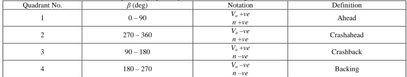
Propellers which are basically designed to produce forward force to propel the ships moving ahead, periodically have to function oppositely. Table 1 provides a wide range of propeller operations across the four quadrants.
Table 1: Notation and definition of four quadrant propeller operation in J, KT and KQ system.
Quadrant No. β (deg) Notation Definition
1 0 – 90 Va +ve
n +ve Ahead
2 270 – 360 Va –ve
n +ve Crashahead
3 90 – 180 Va +ve
n –ve Crashback
4 180 – 270 Va –ve
n –ve Backing
While in steady state operation J varies in a small range of J ∈ [0.6,0.8] (Li et al., 2012), however, when the ship has to be in dynamic conditions such as slowing down, braking or moving astern, especially during harbor operations, the value may significantly changes to even negative. Further, when the propeller rotational speed n approaching zero (n→0), the value of the propeller properties KT, KQ and J will be infinity (∞), causing a wide
range variable becomes troublesome and inconvenient for simulation modeling both analog and digital one (Ye et al., 2012).
Addressing such problems, Li et al. (2002) proposed a Chebyshev polynomial fitting for the identification of propeller properties across four quadrants working operations. The expression possesses the precision need and provides conditions for simulating the all-round propeller dynamics (Chi & Li, 2006). The scheme is advantageous since the advance speed which is representation of the ship and propeller speed required for accurate dynamic models of propeller thrust and torque is difficult to measure on real ships (Pivano et al., 2009). Using the Chebyshev polynomial, the traditional first quadrant of open water propeller characteristics which is represented by the non-dimensional KT and KQ as functions of advance ratio J formulated by
(1)
(2)
(3)
where T and Q are respectively propeller thrust and torque, ρ is water density, n is propeller rotational speed (n ≠ 0), D is propeller diameter and Va is the advance speed are transformed into
(4)
where the coefficients a0 ~ an are the independent polynomial coefficients of thrust and torque properties of
the propeller model referred and Tn is the recursive formula of Chebyshev polynomial of order n given by Eq. 6.
The notation of J' represents the advance ratio bounded within J’ ∈ [-1,1].
(6)
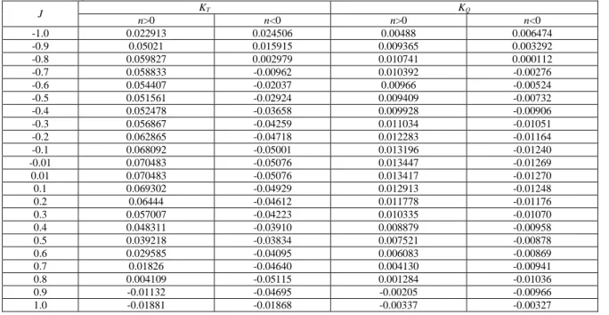
Table 2 summarised the four quadrant open water properties of a Wageningen type B5.88 propeller identified using the fitting of order 8 (n=8). As denoted by Li et al. (2002), order 8 was preferred for the sake of accuracy and efficiency.
Table 2: Ordinary polynomial coefficients bn.
J KT KQ
n>0 n<0 n>0 n<0
-1.0 0.022913 0.024506 0.00488 0.006474
-0.9 0.05021 0.015915 0.009365 0.003292
-0.8 0.059827 0.002979 0.010741 0.000112
-0.7 0.058833 -0.00962 0.010392 -0.00276
-0.6 0.054407 -0.02037 0.00966 -0.00524
-0.5 0.051561 -0.02924 0.009409 -0.00732
-0.4 0.052478 -0.03658 0.009928 -0.00906
-0.3 0.056867 -0.04259 0.011034 -0.01051
-0.2 0.062865 -0.04718 0.012283 -0.01164
-0.1 0.068092 -0.05001 0.013196 -0.01240
-0.01 0.070483 -0.05076 0.013447 -0.01269
0.01 0.070483 -0.05076 0.013417 -0.01270
0.1 0.069302 -0.04929 0.012913 -0.01248
0.2 0.06444 -0.04612 0.011778 -0.01176
0.3 0.057007 -0.04223 0.010335 -0.01070
0.4 0.048311 -0.03910 0.008879 -0.00958
0.5 0.039218 -0.03834 0.007521 -0.00878
0.6 0.029585 -0.04095 0.006083 -0.00869
0.7 0.01826 -0.04640 0.004130 -0.00941
0.8 0.004109 -0.05115 0.001284 -0.01036
0.9 -0.01132 -0.04695 -0.00205 -0.00966
1.0 -0.01881 -0.01868 -0.00337 -0.00327
Transforming the bounded form Chebyshev polynomial of thrust and torque coefficients into ordinary polynomial with order n, the following expressions are obtained.
(7)
(8)
where b0 ~ bn are the ordinary polynomial coefficients gained by extending the Chebyshev recursive
formula Tn.
Table 3 listed the ordinary polynomial coefficients b0 ~ b8 obtained using the fitting.
Table 3: Ordinary polynomial coefficients bn
KT KQ
nth n>0 n<0 n>0 n<0
0 0.51751 -0.37201 11.743775 -4.122745
1 0.04938 0.02806 -5.73842 -12.57114
2 -1.40974 0.80858 -171.7782 44.96884
3 -0.49644 -0.17168 47.5336 82.1984
4 3.71976 -1.57328 533.23328 -109.44128
5 -0.43488 -1.10144 -88.6016 -139.33568
6 -4.584 1.35648 -600.19712 94.19776
7 0.72896 1.08672 46.65344 69.55008
8 1.77152 -0.1984 226.75456 -25.3952
experimental tests with minimum errors as low as 0.01039 and 0.00195 respectively for the thrust and torque properties. Both outcomes are evidence that the method is considerably effective and accurate. Exploitation of such all-round propeller properties in several modeling which is not limited to simulation of propeller loading (Chi and Li, 2006; Jiang et al., 2011), performance simulation of marine diesel engine propulsion system (Izzuddin et al., 2014; Izzuddin et al., 2014; Sunarsih et al., 2015a; Wang et al., 2013) and ship hull system (Li et al., 2012) has further revealed that the method is practically applicable for the evaluation and monitoring of ship and the system performances.
Thrust Generation Model For All Round Ship Manoeuvring Simulation:
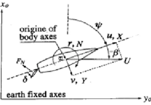
Generally, ship manoeuvring concerns mainly the control of the inherent ship forces through the centre of its mass at ship gravity centre. The ship manoeuvring can thus be modeled as a representation of horizontal movement in a fixed axis system comprises of the ship surge, sway and yaw motions. The coordinate system is as depicted in Fig. 1 where u, v, r and U are respectively the forward (surge) velocity, lateral (sway) velocity, turning velocity and actual ship velocity at mid-ship. X and Y represent the hydrodynamic forces in x and y axis directions while N is the force moment around z axis.
Fig. 1: Ship coordinate system.
Referring to the given coordinate system and Mathematical Modeling Group (MMG) concept which differentiates the forces and moment acting on a ship into three main components namely hull, propeller and rudder, ship manoeuvring model is comprised of ship motion parameters and the hydrodynamics of the three components and the disturbances (Liu et al., 2013) derived from the environmental conditions. The forces and moment can thus be distinctly expressed as dynamical and physical model as follows.
(9)
(10)
(11)
where subscripts H, P and R refer to ship hull, propeller and rudder respectively.
Examining closely into the force in longitudinal direction, the mathematical model of this component is formulated as follows (Kijima et al., 2000 in Maimun et al., 2013).
(12)
where tp is the thrust deduction factor and the propeller force in forward direction which is represented by
the propeller thrust KT is expressed as the function of advance speed ratio J given by 2
3 2 1
)
(J C C J CJ
KT = + + (13)
) /( ) 1 (
cos w nD
U
J = β − P (14)
where C1, C2, C3 are coefficients for open water propeller characteristics , β is drift angle and wp is effective
wake fraction coefficient at propeller location.
Considering the lateral force and moment induced by the propeller is small in forward direction, the values can thus be assumed as zero. Hence
(15)
(16)
Taking advantage of the Chebyshev polynomial fitting to represent the non-dimensional open water properties of thrust coefficient KT, the mathematical model given in Eq. 11 and Eq. 12 can thus be exchanged
with the bounded form Chebyshev properties formulated in Eq. 6 for J’ ∈ [-1,1]. Employing these properties meant enhancing and extending the model into four quadrant-based model which further enables the all-round working of the propeller and ship operations.
Denoting the accuracy and efficiency highlighted by Li et al. (2002) where order 8 (n=8) is preferred, the first quadrant thrust properties given in Eq. 12 is exchanged with the four quadrant properties given in Eq. 17 (the open water properties of KT and J hereinafter are referred to as the bounded four quadrant properties).
8 8 2 2 1
0 ...
)
(J b bJ b J bJ
where b0 ~ b8 are obtained from Table 1 as such for n>0 and n<0, the properties are respectively formulated
as follows.
8
2
77152 . 1 ...
40974 . 1 04938 . 0 0.51751 )
(
J
J J
J KT
+
+ −
+
= (18)
8
2
1984 . 0 ...
80858 . 0 02806 . 0 37211 . 0 ) (
J
J J
J KT
−
+ +
+ −
= (19)
Integration of the four quadrant thrust generation model developed into ship manoeuvring model is as depicted in Fig. 2. The simulation program is developed in MATLAB Simulink platform. Particulars of the ship model is summarised in Table 4. Using the input of advance ratio J and propeller rotational speed n, the thrust generation module possesses the ability to define the quadrant of propeller working operation and generates the thrust properties accordingly.
Table 4: Particulars of ship and model.
Principal Particulars Full Scale Model
Length between perpendicular (L) [m] 266 2.375
Beam (B) [m] 41.6 0.3714
Draft (d) [m] 11.13 0.099
Block Coefficient (Cb) 0.746
Fig. 2: Four quadrant thrust generation module in ship manoeuvring simulation program.
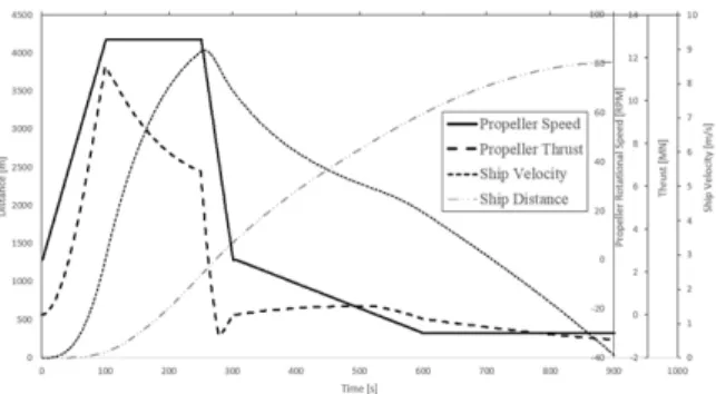
The following Fig. 3 presents real time simulation result of crash stopping condition by fully utilising four quadrants of propeller operations. Simulating the continuous operation of the propeller across four quadrants, the rotational speed is initially set to accelerate to reach 90rpm, being constant for 150s and decelerate to zero for 50s in forward direction. Next, the propeller speed is situated to accelerate in backward direction up to a maximum of 30rpm for 300s and maintained to be constant until the end of the simulation at 900s. Accordingly, the thrust properties reach the highest when the propeller speed is accelerated to in the first 100s and gradually decrease when the propeller speed is set to be constant. The thrust is rapidly decreased when the propeller speed is decelerated to zero for the next 50s. However, there is no significant change when the propeller speed is reaccelerated to 30rpm (in reverse direction) and left to be constant until the end of the simulation. The result analysed reveals that the thrust generated by the propeller fits well as a function of its rotational speed.
Fig. 3: Time series of propeller and ship characteristics in all round working conditions.
Conclusion:
present the dynamics of the propeller and ship characteristics accordingly. The model developed is thus practically applicable to observe ship performance in overall conditions.
ACKNOWLEDGEMENT
The authors would like to thank Institut Sultan Iskandar, Universiti Teknologi Malaysia (ISI-UTM) for financial support.
REFERENCES
Bertram, V., 2012. Practical Ship Hydrodynamics, Elsevier.
Carlton, J., 2012. Marine propellers and propulsion, Butterworth-Heinemann.
Chi, H.H., D.P. Li, 2006. Application of Chebyshev polynomial to simulated modeling. Journal of Marine Science and Application, 5: 38-41.
Eloot, K., M. Vantorre, 2004. Prediction of low-speed manoeuvring based on captive model tests: opportunities and limitations. 31st annual general meeting of IMSF, Antwerp Maritime Academy & Flanders Hydraulics Research, Antwerp, 13-17.
Hwang, W., B. Jakobsen, R. Barr, V. Ankudinov, N. Fuller, L. Vest, M. Morris, A. Mcgovern, A. Landsburg, 2003. An Exploratory Study to Characterize Ship Manoeuvring Performance at Slow Speed. Proceedings of International Conference of Manoeuvring and Control–MCMC2003. Kanazawa.
Kijima, K., Y. Nakiri, Y. Furukawa, 2000. On a prediction method for ship manoeuvrability. Proceedings of the international workshop on ship manoeuvrability-25 years CPMC at HSVA, Hamburg.
Kuiper, G., 1992. The Wageningen propeller series.
Li, D.P., Z.Y. Wang, H.H. Chi, 2002. Chebyshev fitting way and error analysis for propeller atlas across four quadrants. Journal of marine science and application, 1: 52-59.
Li, R., W.X. Zhang, H.Y. Li, 2012. Modeling and Simulation of Propeller and Hull System for Marine Propulsion Plant. Advanced Materials Research, 383: 2121-2125.
Liu, Y., C. Guo, Z. Lei, 2013. Intelligent Control Based on ADRC for Large Container Ship Course Keeping. Proceedings of Chinese Intelligent Automation Conference. Springer, 195-206.
Maimun, A., A. Priyanto, A. Sian, Z. Awal, C. Celement, M. Waqiyuddin, 2013. A mathematical model on manoeuvrability of a LNG tanker in vicinity of bank in restricted water. Safety Science, 53: 34-44.
Pivano, L., T.I. Fossen, T.A. Johansen, 2006. Nonlinear model identification of a marine propeller over four-quadrant operations. the 14th IFAC Symp. Syst. Identification (SYSID).
Pivano, L., T.A. Johansen, O.N. Smogeli, 2009. A four-quadrant thrust estimation scheme for marine propellers: Theory and experiments. IEEE Transactions on Control Systems Technology, 17-215.
Roddy, R.F., D.E. Hess, W. Faller, 2006. Neural Network Predictions of the 4-Quadrant Wageningen Propeller Series. DTIC Document.
Sunarsih, Izzuddin, N., A. Priyanto, 2015a. Thrust and Torque Estimation Scheme Based on Chebyshev Polynomial for Ship Manoeuvring Simulation. Procedia Manufacturing, 2: 359-363.
Sunarsih, Izzuddin, N., A. Priyanto, 2015b. Marine Diesel Engine Simulator for Self Propulsion Test in Evaluating the Fuel Saving Rate. Applied Mechanics and Materials, 799-800: 870-875.
Wang, H.Y., H.Y. Tang, 2012. Modeling and Simulation of Diesel Propulsion System in Maneuvering Navigation Condition. Applied Mechanics and Materials, 128: 1168-1172.
Xiao, B., X. Wang, A.G. Shi, M. Wu, 2011. Four Quadrants Numerical Prediction for Hydrodynamic Performance of Open-Water Propeller. Advanced Materials Research, 143: 1143-1147.