Ann Based Distribution Static Compensator For Power Quality
Improvement With Linear Sinusoidal Tracer Control Algorithm
1Mr. K.Lakshmi Narayana,2Mr. K.V.V.Satya Narayana
1P.G student, EEE, BVC INSTITUTE OF TECHNOLOGY AND SCIENCE, AMALAPURAM, A.P 2ASST.PROF, EEE, BVC INSTITUTE OF TECHNOLOGY AND SCIENCE, AMALAPURAM, A.P
Abstract- In this paper an ANN based DSTATCOM is proposed for reactive power compensation, harmonics elimination, zero voltage regulation, power factor correction, neutral current compensation and unbalance caused by various loads in the distribution system. Various configurations and topologies of DSTATCOM are used for reduction of distortions with acceptable level of performance according to the IEEE-519 standard with an optimal use of dc bus of a voltage source converter (VSC) used as DSTATCOM and in cost-effective manner. This paper presents the effectiveness of adaptive theory based Improved Linear Sinusoidal Tracer control algorithm (ILST). This algorithm is used for extraction of load fundamental active and reactive power components of currents which are used for estimation of reference source currents. The effectiveness of the proposed system designed and simulated under the MATLAB / SIMULINK environment. Simulation results of this system represent the performance of the Improved Linear Sinusoidal Tracer control algorithm (ILST).
Keywords- DSTATCOM, ANN, voltage source converter (VSC), adaptive theory based Improved Linear Sinusoidal Tracer (ILST).
I. INTRODUCTION
In the present scenario of AC transmission network, the mitigation of power quality problems is the major challenge due to increase of power electronic devices [1]. Static power converters such as rectifiers, large number of low-power electronic-based appliances, induction heating, switch mode power supplies, adjustable speed drives, electric traction, cyclo-converters etc. are nonlinear loads that generate considerable distortions in the ac mains current and causing power quality problems [2, 3]. A control algorithm should have good detection accuracy, wide range of adjustment of internal parameters, stability performance, and fast dynamic response. The performance of DSTATCOM depends largely on the right and accurate real-time detection of harmonics and reactive currents etc.. Sawant and Chandorkar have described multifunction active filter using instantaneous p-q-r theory. One of the new applications of active filter is described by Crosier and Wang [7] where it is applied for grid connected electric vehicle charging station. Buenoet al. [8] have described application of active filter for railway supply system. DSTATCOM (Distribution Static Compensator) is also used for power quality improvement in pico-hydro based power generation [9], isolated wind power generation system etc. Singh has described different
configurations of DSTATCOM such as three leg, four leg and characteristics of nonlinear loads. Active filters needs to detect the total distortion current outside the fundamental active source component of currents. A widely used method is the detection algorithm based on the theory of instantaneous reactive power.
Effective use of DSTATCOM is directly related to the design of power circuit components such as dc-bus capacitor, interfacing inductors, and VSC, control algorithm used for the estimation of reference source currents with increased speed and less calculation, switching scheme for gating pulses, and stability issues of a designed control algorithm [18]–[27]. An area of adaptive control provides an automatic adjustment of the controller gains and parameters in real time, in order to achieve a desired level of performance. It provides an automatic tuning procedure in a closed loop for the controller parameters. Characteristics of these control algorithms are the ability to extract necessary information from real online data in order to tune the controller, and also used for grid synchronization [28], [29].
In synchronized filtered-x algorithm-based adaptive control [30], a proportional regulator is used to improve the dynamic performance of the system because it needs high gain at only fundamental and harmonic frequencies of the load currents. Thus, it is suitable only for filtering harmonics currents from one or more specified harmonic-producing loads. An algorithm based on adaptive interference canceling theory [31] requires a continuously updating closed-loop system, and its operating characteristics are almost independent of the parameter variations of the elements due to temperature or oldness of system. It requires a band-pass filter and an integrator where the performance of a filter depends upon selected cutoff frequencies. An iterative algorithm for adaptive harmonic detection [32] proposed by Zeng and Li is based on coherent average estimation (CAE). CAE is used to detect a weak periodic signal. The method is used in periodic signal to filter out undesirable components and extract the useful signals. It requires knowledge and count of cycles. If this information is correctly known, then a single cycle of some signals can be taken for process.
[34] have proposed an adaptive notch filter, which is suitable for the estimation of a fundamental frequency signal from distorted signals. It is also capable of changing the notch frequency according to tracking of frequency variations of the input signal. It is also used under the assumption of slow adaptation. But, uncertainty in the frequency estimation due to the noise makes this division erroneous and inoperative. In a fuzzy-adaptive hysteresis controller [35], the performance of the system depends upon assumption in the design of fuzzy logic controller rules. It is also applied in a current controller to derive the switching signals and control of dc-bus voltage of the VSC. The variable step-size LMS algorithm [36] is based on autocorrelation time mean estimate of error signal to update the step size. It is able to suppress the effect of the harmonic components on the estimation of updated step size. Fast convergence rate, a small steady-state error, and a good noise immunity performance are the main advantages of this algorithm but performance and stability of controller depend upon the value of the estimated step size. In an adaptive theory-based linear sinusoidal tracer [37], error detection accuracy and dynamic response both are related to each other.
An error in the linear sinusoid tracer algorithm is affected by the high-order harmonics. Thus, this algorithm is not able to detect harmonics current accurately. For removal of this limitation, a low-pass filter (LPF) is used and this modification is named as an adaptive theory-based improved linear sinusoid tracer (ILST) where source current and reference current both are tracing each other without any change even at unbalance loads. Its structure is simple. Theoretical study of this algorithm for the estimation of fundamental signal is reported by Du and Su [37]. However, it has been limited to the simulation study of extraction of signals of single-phase loads. In an adaptive theory-based improved linear sinusoidal tracer control algorithm is implemented on a DSTATCOM for the extraction of load currents’ fundamental components in three phase consumer loads. It is used for power factor correction (PFC) and ZVR along with load balancing and harmonics elimination.
Good detection accuracy, wide range of adjustment of internal parameters, stability performance, and fast dynamic response are the main features of this control algorithm. Internal parameters of this algorithm have clear physical understanding and easy adjustable to optimal value, which show the simplicity of this algorithm. Frequency- and time-domain characteristics of the ILST are not affected due to external environment changes.
Detection accuracy and speed of the dynamic response can be tuned after adjusting algorithm internal parameters. For the desired frequency and bandwidth, the ILST control algorithm is able to extract instantaneous value and the amplitude of a sinusoidal by least-squares error, gradient descent method, and rotation transform. To achieve an ideal performance, the value of constant ρis equal to the source frequency ωo and the band width ψ should be an optimal value. In this algorithm, extracted reference source currents exactly follow the actual source currents during steady-state as well as dynamic conditions. For this reason, three-phase source currents have smooth variation during load perturbations. This control algorithm is implemented on a
DSTATCOM for compensation of linear and nonlinear loads.
II. SYSTEM CONGURATION
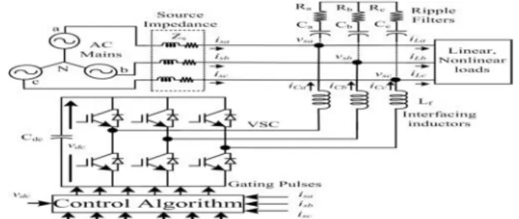
A VSC-based DSTATCOM is shown in Fig. 1. It is connected to a three-phase AC mains feeding three-phase linear/nonlinear loads with grid source impendence .For reducing ripple in compensating currents, interfacing inductors are used at an AC side of the VSC.A zig-zag/ three single-phase transformeris used for neutral current compensation. A three-phase series combination of capacitor ( , , ) and a resistor ( , , ) represent the passive ripple filter, which is connected at point of common coupling (PCC) for filtering the high frequency switching noise of the VSC. Generally, the same value of series-connected capacitor and resistance as a ripple filter is used in all the three phases. The DSTATCOM currents are injected as required compensating currents to cancel the reactive power components and harmonics of the load currents so that loading due to reactive power component/harmonics is reduced on the distribution system. The rating of the insulated gate bipolar transistor (IGBT) switches of the VSC is based on the voltage and current rating for the required compensation. For a considered load of 50 kVA (0.8 lagging), the compensator data are given in Appendix A. The rating of the VSC for the reactive power compensation/harmonics elimination is found to be 35 kVA (approximate 15% higher than the reactive power from rated value). The designed value of different auxiliary components of DSTATCOM such as interfacing ac inductors, dc-bus voltage, and value of dc-bus capacitor are also given in Appendix A.
Fig. 1. Schematic diagram of VSC-based DSTATCOM
III. CONTROL ALGORITHM A. Adaptive ILST Control Algorithm
reference current both are tracing each other without any change even at unbalance loads. Three-phase voltages at the PCC are sensed and their amplitude is calculated using PCC phase voltages (v ,v andv )
= (1)
Unit template inphase with phase voltages(w ,w and w )are estimated as
w = , w = , w = (2)
Similarly, the quadrature unit templates (w ,w and w )are given as:
w = √ ;w =
√ ;
w = √ (3)
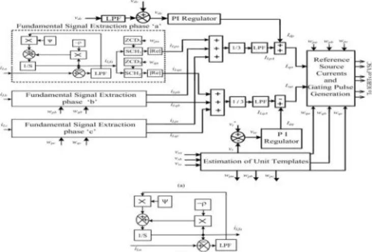
Major components in the distorted load currents are fundamental active power, reactive power, harmonics components, and dc components. An adaptive theory-based ILST [54] with selectable frequency and bandwidth is used to estimate the phase “a” load fundamental current i as shown in the block diagram of Fig. 2(b).
In this control algorithm, phase ‘a’ fundamental load current is subtracted from the load current to estimate the current error signal. The filtered value of a current error signal with the combination of band-pass filter (ψ) is added with the output signal, which is multiplied by the power frequency signal (–ρ). After integration of this signal, phase “a” fundamental load current i is estimated. Similar procedure is adapted for phase ‘b’and phase ‘c’to extract to fundamental components of load currents. The amplitudes of three-phase fundamental load active power current components (i ,i and i ) are extracted at the zero crossing of the unit template in-phase of PCC voltages.An output of zero crossing detector (ZCD ) works as a trigger pulse of signal and hold logic (SCH_1 ) and fundamental current as an input signal ofSCH . The real component of the SCH output is known as the amplitude of fundamental active power components.
Fig. 2 (a) Generation of reference source currents using an adaptive theory-based ILST control algorithm (b) Estimation of the fundamental signal using an adaptive theory-based ILST control algorithm.
The average amplitude of fundamental active power components (I ) is estimated using amplitude sum of three-phase load active power components (i ,i and i ) divided by three for load balancing. First-order low-pass filters are used to separate the low-frequency components. Mathematically, it is expressed as:
I = (4)
Similarly, amplitudes of reactive power components (i ,i and i ) of fundamental load currents are extracted at the zero crossing of the quadrature unit template phase of PCC voltages using zero-crossing detector (ZCD ) and signal and hold logic (SHC ). An output signal of SHC2 is known as the amplitude of fundamental reactive power components of load current. The average amplitude of the fundamental reactive power component I is estimated using load fundamental reactive power current componentsi ,i andi .Alow-pass filter is used to extract its smooth or ripple-free component. Mathematical expression of the average amplitude of the fundamental reactive power current componentI is given as:
I = (5)
Fig. 2(b) shows the subsection of an adaptive theory-based ILST control algorithm. The transfer function
(s) of a lowpass filter is as:
G (s) = (6)
Whereτ is the time constant of a L.P.F. and it is greater than zero. The transfer function in Fig. 2(b)in terms of phase ‘a’, extracted fundamental currenti and load currenti canbe written as:
C(s)= (s) = ( )
( ) ( ) (7)
Where forward path transfer function:
G(s) =
( ) ; and feedback transfer function
H(s) = 1.
The characteristics equation of the transfer function is written as:
s + (τρ + 1)s + (ρ + ψ) = 0 (8)
Where τ = time constant of a low-pass filter, ρ = power frequency, ψ = frequency band of a band-pass filter. Stability of characteristic equation is analyzed using a Rough–Hurwitz criterion. Details of this analysis are given in the Appendix B. Reference dc-bus voltagev∗ and sensed dc-bus voltagev of a VSC are compared and error in dc-bus voltage at the kth sampling instant is expressed as:
v (k) = v∗ (k) − v (k) (9)
This dc-bus voltage error v is fed to a proportional– integral (PI) regulator whose output is required for maintaining dc-bus voltage of the DSTATCOM. Its output at the kth sampling instant is given
andI (k)and I (k − 1) are the amplitudes of the active power component of the fundamental reference current at kth and (k–1)th instants. The amplitude of active power current components of the reference source current I is calculated by an addition of output of dc-bus PI controller I and an average magnitude of the load active power component of currentsI as:
I = I + I (11)
A reactive power component of reference source currents is required for the operation of DSTATCOM in the ZVR mode. In the ZVR mode, source currents are slightly leading from the ac mains voltages because extra leading reactive power component is required for regulating the voltage at PCC. It is zero in the operation of DSTATCOM in the PFC mode. The voltage error between reference PCC voltagev∗ and its sensed valuevis fed to the PCC voltage PI controller. The voltage errorv of ac voltage at the kth sampling instant is given as:
v (k) = v∗(k) − v (k) (12)
The output of the PCC voltage PI controllerI for maintaining PCC terminal voltage to a constant value at the kth sampling instant is given as:
I (k) = I (k − 1)
+k {v (k) − v (k − 1)} + k v (k) (13) WhereI (k) is a part of the reactive power component of source current and it is named asI .k and k are the proportional and integral gain constants of the PCC voltage PI controller. Gains of PI controller for dc-bus voltage: k = 2.4, k = 1.54; gains of the PCC voltage PI controller: k = 3.1, k = 0.95. The amplitude of reactive power current components of the reference source current I is calculated by subtracting average load reactive currentsi from the output of voltage PI controllerI as
I = I − I (14)
Three-phase reference source active and reactive power components of currents are estimated using amplitude of three phases (a, b, and c) load active and reactive power current components, PCC voltages in-phase, and quadrature voltage unit templates as:
= , = , = (15)
= , = , = (16)
Reference source currents ( ∗ , ∗ and ∗) are estimated by the addition of reference active and reactive power components of currents as:
∗ = + , ∗ = + , (17)
∗ = + (18)
The sensed source currents ( , ) and these reference source currents ( ∗ , ∗ ∗ ) are compared for respective phases and each phase current error is amplified using PI current regulators and their outputs are compared with a carrier signal of 10 kHz to generate the gating signals for IGBT switches of VSC used as DSTATCOM.
In this paper ANN controller is used instead of PI controller to improve the results and decrease the %THD.
Comparision table shows the effectiveness o ANN controller over PI controller.
B. ANN controller:
An ANN is essentially a cluster of suitably interconnected nonlinear elements of very simple form that possess the ability of learning and adaptation. These networks are characterised by their topology, the way in which they communicate with their environment, the manner in which they are trained and their ability to process information. Their ease of use, inherent reliability and fault tolerance has made ANNs a viable medium for control. An alternative to fuzzy controllers in many cases, neural controllers share the need to replace hard controllers with intelligent controllers in order to increase control quality. A feed forward neural network works as compensation signal generator. This network is designed with three layers. The input layer with seven neurons, the hidden layer with 21 and the output.
The training algorithm used is Levenberg–Marquardt Backpropagation (LMBP).
Training is given as follows:-net=newff(minmax(P),[7,21,3],
{„tansig‟,‟tansig‟,‟purelin‟},‟trainlm‟); net.trainParam.show =50;
net.trainParam.lr = .05; net.trainParam.mc = 0.95; net.trainParam.lr_inc = 1.9; net.trainParam.lr_dec = 0.15; net.trainParam.epochs = 1000; net.trainParam.goal = 1e-6; [net,tr]=train(net,P,T); a=sim(net,P);
gensim(net,-1);
IV. SIMULATION RESULTS
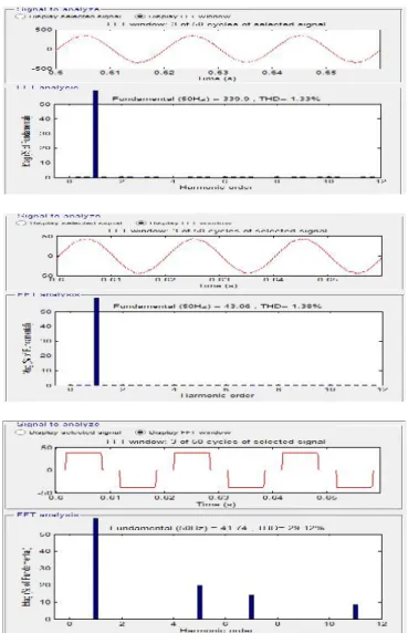
In the ZVR mode, the amplitude of PCC voltage is regulated to the reference amplitude by injecting the leading reactive power components. Fig. 3 shows the dynamic performance of the DSTATCOM used for reactive power compensation to achieve ZVR and load balancing under linear loads (at t = 1.35–1.45 s). The performance indices are as PCC phase voltages (vs ), balanced source currents (is ), load currents (iLa, iLb, and iLc, compensator currents (iCa, iCb, and iCc), amplitude of voltages at PCC (vt ), and dc-bus voltage (vdc) under time-varying linear loads. The performance of DSTATCOM is also studied under uncontrolled rectifier-based nonlinear loads. The dynamic performance of DSTATCOM in terms of waveforms and harmonics spectra of phase “a” voltage at PCCvsa , source
current isa , and load current iLa are shown in Figs. 4 and 5(a)–(c), respectively.
summarized results demonstrating the performance of DSTATCOM. These results show satisfactory performance of DSTATCOM for reactive power compensation, harmonic elimination, and load balancing of linear and nonlinear loads.
Fig. 3 Dynamic performance of DSTATCOM under varying linear loads in the ZVR mode with ANN controller
Fig. 4 Dynamic performance of DSTATCOM under varying nonlinear loads in the ZVR mode
Fig. 5 Waveforms and harmonic spectra of (a) PCC voltage of phase “a,” (b) source current of phase “a,” and (c) load
current of phase “a” in the ZVRmode. TABLE-I
COMPARISION BETWEEN PI & ANN
V. CONCLUSION
load balancing have been demonstrated in ZVR mode. From these results, it is concluded that DSTATCOM and its control algorithm with ANN controller have been found suitable for time-varying loads. PCC and DC bus voltages of the DSTATCOM have also been regulated to reference values under unbalanced loads.
VI. Acknowledgment
This paper is based on M. Tech. project carried out by the student of BVC Institute of Technology And Science, Amalapuram studying M.Tech (Power System). The project had been completed by Mr. K.LAKSHMI NARAYANA, Mail id: [email protected], under the guidance of Mr. K.V.V.SATYA NARAYANA.
APPENDIX A
AC supply source: three-Phase, 415 V (L–L), 50 Hz; source
impedance: Rs= 0.07 Ω, Ls = 2 mH; Load: 1) Linear: 50
kVA, 0.8 p.f. lagging; 2) Nonlinear: three-phase full-bridge uncontrolled rectifier with R= 15 Ω andL = 100 mH; ripple
filter: Rf = 5 Ω,Cf = 7 μF; dc-bus capacitance: 12000 μF; reference dc-bus voltage: 700 V; interfacing inductor Lf = 2.5 mH; gains of PI controller for dc-bus voltage: kpd = 2.4,
kid = 1.54; gains of the PCC voltage PI controller: kpt = 3.1, kit = 0.95.
REFERENCES
[1] George J. Wakileh, Power System Harmonics: Fundamental, Analysis, and Filter Design. New York:
Springer-Verlag, 2007.
[2] S. Chattopadhyay, M. Mitraand, and S. Sengupta,
Electric Power Quality. New York: Springer Verlag, 2011.
[3] A. Sannino, J. Svensson, and T. Larsson, “Review power-electronic solutions to power quality problems,” J. Elect. Power Syst. Res., vol. 66, pp. 71–82, 2003.
[4] B. Singh, P. Jayaprakash, and D. P. Kothari, “Power factor correction and power quality improvement in the distribution system,”Elect. India, pp. 40–48, Apr. 2008. [5] T. L. Lee and S. H.Hu, “Discrete frequency-tuning active filter to suppress harmonic resonances of closed-loop distribution power systems,”IEEE Trans. Power Electron.,
vol. 26, no. 1, pp. 137–148, Jan. 2011.
[6] F. Barrero, S.Mart´ınez, F.Yeves, and P. M.Mart´ınez, “Active power filters for line conditioning: A critical evaluation,”IEEE Trans. Power Delivery, vol. 15, no. 1, pp.
319–325, Jan. 2000.
[7] J.-C. Wu, H.-L. Jou, Y.-T. Feng, W.-P. Hsu, M.-S. Huang, and W.-J. Hou, “Novel circuit topology for three-phase active power filter,” IEEE Trans. Power Delivery,
vol. 22, no. 1, pp. 444–449, Jan. 2007.
[8] K. Sano and M. Takasaki, “A transformerless DSTATCOM based on a multivoltage cascade converter requiring no DC sources,” IEEE Trans. Power Electron.,
vol. 27, no. 6, pp. 2783–2795, Jun. 2012.
[9] S. Du, J. Liu, and J. Lin, “Hybrid cascaded H-bridge converter for harmoniccurrent compensation,”IEEE Trans. Power Electron, vol. 28, no. 5, pp. 2170–2179, May 2013. [10] “IEEE recommended practices and requirement for harmonic control onelectric power System,” IEEE Std. 519, 1992
[11] L. Asiminoaei, C. Lascu, F. Blaabjerg, and I. Boldea, “Performance improvement of shunt active power filter with dual parallel topology,” IEEE Trans. Power Electron., vol.
22, no. 1, pp. 247–259, Jan. 2007.
[12] S. B. Karanki, N. Geddada, M. K. Mishra, and B. K. Kumar, “A DSTATCOM topology with reduced DC link voltage rating for load compensation with non-stiff source,”
IEEE Trans. Power Electron., vol. 27, no. 3, pp. 1201–1211, Mar. 2012.
[13] V. Rajagopal, B. Singh, and G. K. Kasal, “Electronic load controller with power quality improvement of isolated induction generator for small hydro power generation,”IET Renew. Power Gener., vol. 5, no. 2, pp. 202–213, 2011. [14] B. Singh and J. Solanki, “Load compensation for diesel generator-based isolated generation system employing DSTATCOM,” IEEE Trans. Ind. Appl., vol. 47, no. 1, pp.
238–244, Jan./Feb. 2011.
[15] H. Hu, W. Shi, Y. Lu, and Y. Xing, “Design considerations for DSP controlled 400 Hz shunt active power filter in an aircraft power system,” IEEE Trans. Ind. Electron., vol. 59, no. 9, pp. 3624–3634, Sep. 2012.
[16] S. Sharma and B. Singh, “Performance of voltage and frequency controller in isolated wind power generation for a three-phase four-wire system,” IEEE Trans. Power Electron., vol. 26, no. 12, pp. 3443–3452, Dec. 2011. [17] R. K. Varma, V. Khadkikar, and R. Seethapathy, “Nighttime application of PV solar farm as STATCOM to regulate grid voltage,” IEEE Trans. Energy Convers., vol.
24, no. 4, pp. 983–985, Dec. 2009.
[18] B. Singh, P. Jayaprakash, T. R. Somayajulu,D. P.Kothari,A.Chandra, and K. Al-Haddad, “Integrated three-leg VSC with a zig-zag transformer based three-phase four-wire DSTATCOM for power quality improvement,” in
Proc. 34th IEEE Annu. Conf. Ind. Electron., 2008, pp. 796– 801.
[19] N. Mariun, A. Alam, S. Mahmod, and H. Hizam, “Review of control strategies for power quality conditioners,” inProc. Nat. Power Energy Conf., 2004, pp.
109–115.
[20] Y. F. Wang and Y. W. Li, “A grid fundamental and harmonic components detectionmethod for single-phase systems,”IEEE Trans. Power Electron., vol. 28, no. 5, pp.
2204–2213, May 2013.
[21] L. Asiminoaei, F. Blaabjerg, and S. Hansen, “Detection is key- harmonic detection methods for active power filter applications,”IEEE Ind. Appl. Mag., vol. 13, no. 4, pp. 22– 33, Jul./Aug. 2007.
[22] S. Chen and G. Joos, “Direct power control of active filter with averaged switching frequency regulation,” in
Proc. 35th lEEE Annu. Power Elecrron. Spec. Conf., 2004,
pp. 1187–1193.
[25] L. Asiminoaei, P. Rodriguez, and F. Blaabjerg, “Application of discontinuous PWM modulation in active power filters,”IEEE Trans. Power Electron., vol. 23, no. 4,
pp. 1692–1706, Jul. 2008.
[26] V. George andM. K.Mishra, “Design and analysis of user-defined constant switching frequency current-control-based four-leg DSTATCOM,” IEEE Trans. Power Electron., vol. 24, no. 9, pp. 2148–2158, Sep. 2009.
[27] K. Ogata, Modern Control Engineering, 4th ed. Delhi, India: Pearson Education Asia, 2002.
[28] I. D. Landau, R. Lozano, M. M’Saad, and A. Karimi, “Adaptive control: Algorithms, analysis, and applications,” 2nd ed. London: Springer-Verlag, 2011.
[29] S. G. Jorge, C. A. Busada, and J. A. Solsona, “Frequency adaptive discretefilter for grid synchronization under distorted voltages,” IEEE Trans. Power Electron.,
vol. 27, no. 8, pp. 3584–3594, Aug. 2012.
[30] R. Zahira and A. P. Fathima, “A technical survey on control strategies ofactive filter for harmonic suppression,”
J. Procedia Eng., vol. 30, pp. 686–693, 2012.
[31] Y. Zhang and Y. Tang, “Active power filter based on adaptive detecting approach of harmonic currents,” J. Electromagn. Anal. Appl., vol. 1, pp. 240–244, 2009. [32] L. Zeng and X. Li, “Research on harmonic suppression in power system based on improved adaptive filter,” J. Energy Procedia, vol. 16, pp. 1479–1486, 2012.
[33] P. Mitra and G. K. Venayagamoorthy, “An adaptive control strategy for DSTATCOM applications in an electric ship power system,”IEEE Trans. Power Electron., vol. 25,
no. 1, pp. 95–104, Jan. 2010.
[34] M. Mojiri, M. K. Ghartemani, and A. Bakhshai, “Time-domain signal analysis using adaptive notch filter,” IEEE Trans. Signal Process., vol. 55, no. 1, pp. 85–93, Jan. 2007. [35] R. Ponpandi and D. Durairaj, “A Novel fuzzy-adaptive hysteresis controller based three phase four wire-four leg shunt active filter for harmonic and reactive power compensation,”J. Energy Power Eng., vol. 3, pp. 422–435, 2011.
[36] J. Yang, J. Guan, Y. Ning, and Q. Liu, “A novel adaptive harmonic detecting algorithm applied to active power filters,” in Proc. 3rd Int. Congr. Image Signal Process., Oct. 16-18 2010, vol. 7, pp. 3287–3290.
[37] S. wu Du and J.-m. Su, “Analysis of an improved harmonic currents detection method based on LST,” in