Design and Optimization of Leaf Spring Using Composites
1V.Satyanarayana, 2V.V.Ramakraishna,3Sanmala Rajasekhar,4K.V.R.Murthy1
M. Tech. Student, 2Assistant.Professor, 3Associate.Professor Dept of ME, KITS, Divili.
4Reserch Scholar
Abstract: - Leaf spring are designed for the suspension in wheeled vehicles. Now a days all The automobile industries increased interest in the replacement of steel spring with fiberglass composite leaf spring for high strength to weight ratio. In this work a leaf spring are designed for heavy vehicle. In this designing leaf spring following four cases are considered: by modifying the thickness, and no. of leaves, changing camber and changing span. These cases are also considered: Modeling of Road Irregularity, Variation of moving frequency with vehicle speed. Present used material is Steel for leaf spring. In this work, the material is replaced with composites since they are less dense than steel and have good strength The composites used are S2 – Glass Fiber and Epoxy Matrix Composite reinforced by 50% Kevlar fibers. The design is made for leaf spring using Mild Steel, S2–Glass Fiber and Epoxy Matrix Composite reinforced by 50% Kevlar fibers and all the models are designed in CATIA. . The strength validation is done using FEA software ANSYS. Analysis is done by layer stacking method for composites by changing reinforcement angles for 3 layers, 5 layers and 11 layers. Frequency analysis is also determine the frequencies. CATIA software is used for modeling and ANSYS is used for analysis.
1. INTRODUCTION
To achieve the needs of natural resources conversion, energy economy and improving riding qualities of the automobile manufacturers and their subcontractors are attempting to reduce the weight of the vehicles in recent years. To reduce vehicle weight, three techniques have been studied rationalizing the body structure, utilizing light weight materials for parts and decreasing the size of the vehicles. To achieve this attempts are being made by replacing existing material with low cost, high strength, weight ratio materials. In this approach by introducing composite materials into automobile industries, which is having low cost, high strength weight ratio and excellent corrosive resistance can fulfill the requirement. The suspension leaf spring is one of the potential entity for weight reduction in
automobiles as it results in large un sprung mass. It is anticipated that their weight reductions will lead to improvements in riding qualities and in noise and vibration characteristics.
The introduction of fiber reinforced plastics (FRP) is used to reduce the weight of the product without any reduction on load carrying capacity and spring rate. Because of the materials high strain energy storage capacity and high strength-to-weight ratio compared to steel, multi-leaf springs are being replaced by mono-leaf FRP spring. FRP springs also have excellent fatigue resistance and durability. The leaf spring has to sustain the major road loads and crash loads. In addition they deliver an acceptable level of vehicle dynamics making the passenger to enjoy a comfortable ride. The use of FRP in Indian automobiles is very limited. There is also no organized effort to develop automotive components using FRP, although it is advantages over traditional materials such as steel. Composite leaf spring is designed according to the design procedure but it is not completely confirmed that it is withstanding static and dynamic loads. This is because it is very difficult to find the mechanical properties accurately.
2. PURPOSE OF THE SUSPENSION SYSTEM A suspension system is one having springs and other devices that insulate the chassis of a vehicle from shocks transmitted through the wheels. We review suspension system components and how they work together, we must remember that a vehicle in motion is more than wheels turning., The suspension system is in a dynamic state of balance when the tire revolves continuously compensating and adjusting for changing driving conditions. Today’s suspension system is best in automotive engineering.
2.1 MAIN COMPONENTS OF SUSPENSION SYSTEM
1. Struts
2. Shock absorbers 3. Springs
These components of suspension system perform six basic functions:
1. Maintain correct vehicle ride height. 2. Reduce the effort of shock forces. 3. Maintain correct wheel alignment. 4. Support vehicle weight.
5. Keep the tires in contact with road. 6. Controls the vehicle’s direction of travel. 7.
2.2 SUSPENSION SYSTEM
The automobile chassis is mounted by the axles, not directly but through some form of springs. This is done to isolate the vehicle body from the road shocks which may be in the form of bounce, pitch, roll or sway. These tendency’sgive rise to an uncomfortable ride and also cause additional stress in the automobile frame and body. All the part performs the function of isolating the automobile from the road shocks are collectively called a suspension system. It also includes the spring device and various mountings.
A suspension system consists of a spring and a damper. The energy of road shock causes the spring to oscillate. These oscillations are restricted to a reasonable level by the damper, which is more commonly called a shock absorber.
2.3 BASIC CONSIDERATION
When the road, wheel comes across a bump or pit on the road, it is subjected to vertical forces, tensile or compressive, depending upon the nature of the road irregularity. These are absorbed by the elastic compression shear, bending or twisting of the spring. The mode of the spring resistance depends upon the type of material and spring used. Further when the front wheel strikes a bump it starts vibrating.
These vibrations will die down exponentially due to damping present in the system the rear wheel, however, reaches the same bump after certain time depending on the wheel base and the speed of the vehicle of course, when the rear wheel reaches the bump, it experiences similar vibrations as experienced by the front wheel sometime ago. It is seen that to reduce pitching tendency of the vehicle, frequency of the front springing system be less than that of the rear springing system.
From human comfort it is seen that it is desirable to have low vibration frequencies. The results of the studies of human beings have shown that the maximum amplitude which may be allowed for a certain level of discomfort decreases with the
A spring is also defined as an elastic body, whose function is to distort when loaded and to recover its original shape when the load is removed. The various important applications of springs are as follows:
1. Absorb or control energy due to either shock or vibration as in car springs, railway buffers, air-craft landing gears, shock absorbers and vibration dampers.
2. To apply forces in brakes, clutches and spring loaded valves.
3 . To control motion to maintain contact between two elements as in cams and followers.
4. To measure forces, as in spring balances and engine indicators.
5. To store energy, as in watches, toys, etc. 2.5 TYPES OF SPRINGS
There are many types of the springs, yet the following, according to their shapes. Those are important from the subject point of view.
2.5.1 HELICAL SPRINGS
The helical springs are made up of wire coiled in the form of a helix and are primarily intended for compressive or tensile loads. The cross-section of the biform which the spring is made may be circular, square or rectangular. The two forms of helical springs are compression helical spring and tension helical spring.
FIG 2.1 COMPRESSION AND TENSILE HELICAL SPRINGS
In open coiled helical springs, the spring wire is coiled then there is a gap between the two consecutive turns, as the result of which the helix angle is large. Since the application of open coiled helical springs are limited, therefore our discussion shall confine to closely coil helical springs only.
The helical springs have the following advantages:
1. Easy to manufacture. 2. Available in wide range. 3. Reliable.
4. These have constant spring rate.
5. Their performance can be predicted more accurately
6. Their characteristics can be varied by changing dimensions.
2.5.2 CONICAL AND VOLUTE SPRINGS The conical and Volute springs(in volute spring) are used in special applications where as telescoping spring with a spring rate that increases with the load is desired. The conical spring is wound with a uniform pitch where as the volute springs are wound in the form of parabolic with constant pitch and lead angles. The springs may be made either partially or completely telescoping. In either case, the number of active coils gradually decreases. The decreasing number of coils results to increasing spring rate. The characteristic is sometimes utilized in vibration problems where springs are used to support a body that has a varying mass.
The major stresses produced in conical and volute springs are also shear stresses due to twisting.
FIG 2.2 CONICAL & VOLUTE SPRINGS 2.5.3 TORSION SPRINGS
These springs are helical or spiral type. The helical type may be used only in applications. Where the load tends to wind up the spring and are used in various electrical mechanisms. The spiral type is also used where the load tends to increase the number of coils and when made of flat strip are used in watches and clocks.
The major stresses produced in torsion springs are tensile and compressive due to bending.
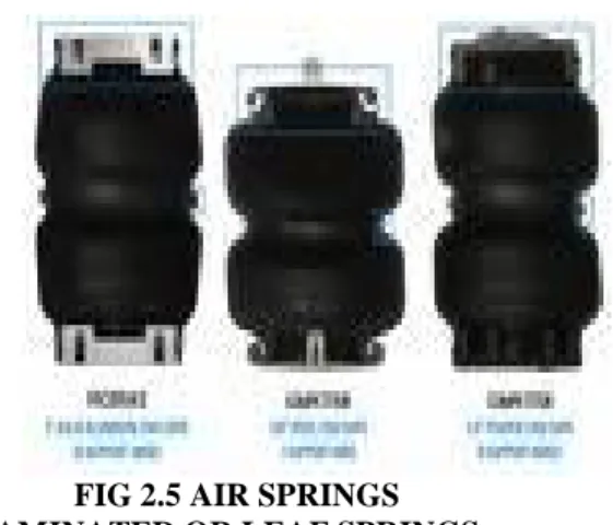
Fig 2.4 SPIRAL TORSION 2.5.4 AIR SPRINGS
The air spring is a rubber cylinder type filled with compressed air .A piston attached to arm when the piston moves up and down with the lower control arm .This causes the compressed air to provide spring action .if the vehicles load change ,a valve at the top of the airbag opens to add or release air from the air springs . An onboard compressor supplies air.
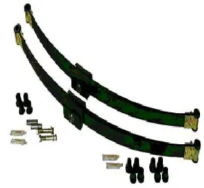
FIG 2.5 AIR SPRINGS 2.5.5 LAMINATED OR LEAF SPRINGS
The laminated or semi elliptical or leaf spring consists of a number of flat plates of varying lengths held together by means of clamps and bolts. These are mostly used in automobiles. The major tensile and compressive stresses produced in leaf springs.
FIG 2.6 GRADUATED LEAF SPRING ASSEMBLY
2.5.6. DISC OR BELLEVILLE SPRINGS
These springs consists of a number of conical discs held together against slipping by a central bolt or tube. These springs are used in applications in high spring rates and compact spring units are required.
The major stresses produced in disc or Belleville springs are tensile and compressive stresses.
2.5.7 SPECIAL PURPOSE SPRINGS
Special purpose springs are air or liquid springs, rubber springs, ring springs etc. The fluids can behave as a compression spring. These springs are used for special type of application. 2.6 SPRING DESIGN
It is important to understand sprung and un sprung weight. Sprung weight is the weight supported by the springs. For example, the vehicle’s body, transmission frame, and motor would be spring weight. Un spring weight is the weight is not carried by springs, such as the tires, wheels and brake assemblies. The springs allow the frame and vehicle to ride undisturbed while the suspension and tires follow the road surface. Reducing un sprung weight will provide less road shock. A high sprung weight along with a low un spring weight provides improved ride and also improved tire traction.
There are four major spring designs in use today. They are
during acceleration, braking and turning, general movement caused by the road undulations. Leaf springs are designed in two methods: multi-leaf and mono leaf. The multi-leaf spring is made of several steel plates of different lengths stacked together. During normal operation, the spring compresses to absorb road shock. The leaf spring bends and slide on each other allowing suspension movement. An example of a mono-leaf spring is the tapered leaf spring. The leaf is thick in the middle and tapers towards the two ends. Many of these leaf springs are made of composite material, while others are made of steel. In most cases leaf springs are used in pairs mounted longitudinally (front and back). However, there is an increasing number of vehicle manufacturers using single transverse (side to side) mounted leaf spring.
Three types of leaf springs are: 1. Laminated or Multi-leaf springs. 2. Single or Mono-leaf springs. 3. Tapered leaf springs.
The third type of leaf spring is the combination of the above two. The multi-leaf springs are commonly used in the automobile suspension system at the rear side and are still in use for commercial vehicles suspension system. It consists of a number of steel strips or leaves placed on the top of each other and then clamped together. The type of application and load carried determines the length and number of leaves. The top leaf is called as the main leaf and the ends of the leaf are rolled to form the eye of the spring. This is for attachment to the vehicle chassis or body. The spring eye allows movement about the shackle and pin at the rear.
3. COMPOSITE LEAF SPRING 3.1COMPOSITES
In composite materials signifies that two or more materials are combined on a macroscopic scale to form a useful material. Composites consist of one or more discontinuous phases entrenched in a continuous phase. The discontinuous phase is usually harder and stronger than the continuous phase and is called the reinforcing agent. The continuous phase is called the matrix. Both the fibers and matrix retain their physical and chemical identities but produce a combination of properties that cannot be achieved with either of the constituents alone. In general, fibers are most important load carrying members, while the surrounding matrix keeps them in the desired location and orientation and acts as a load transfer medium between them and protects them environmental damages due to elevated temperature and humidity.
.
3.2 FIBER REINFORCED PLASTIC LEAF SPRING
FRP leaf springs are generally designed as a mono leaf beam. The mono leaf design is possible with FRP, since the material can be designed for high strength and good deflection characteristics. FRP leaf springs are extensively made using the unidirectional glass fiber because of its good combination of mechanical properties and of its low cost. Fatigue characteristics as well as deflection characteristics are good for composites. FRP leaf springs are extensively made using unidirectional glass fiber because of its good combination of mechanical properties and low cost. Fatigue characteristics of composite are different from that of metals. For simple tension unidirectional composites, the fatigue limits are generally of higher percentages of tensile strength. Thus the durability, of composite leaf spring is superior to that of conventional leaf spring under fatigue loading unlike the conventional multi-leaf springs; the spring’s eyes for composite leaf spring are separately made and joined to the FRP leaf spring because different materials are used for spring and eyes.
FIG 3.1 COMPOSITE LEAF SPRING ASSEMBLY
Manufacturing of eyes with composite material is very difficult and also is a laborious process. The eyes are made in metal and joined to the composite material either by adhesive bonding or mechanical fastening. Since the unidirectional glass fiber reinforced epoxy system is sensitive for fiber discontinuity, the joint design becomes very critical. 4. 3-DIMENSIONAL FINITE ELEMENT
To design composite leaf spring, a stress analysis performed using the finite element method complete using ANSYS software. Modeling was finished for every leaf with eight-node 3D brick element (solid 45) and five-node 3D contact element (contact 49) used to represent contact and sliding between adjacent surfaces of leaves. Also, analysis conceded for composite leaf spring with bonded end joints for Glass/Epoxy, Graphite/Epoxy and Carbon/Epoxy composite materials and the results are compared with steel leaf spring with eye end. The maximum peel and shear stresses along the adhesive layer were measured. The maximum peel and shear stresses along the bonded adhesive layer for glass/epoxy were measured and plotted as shown below.
Fig-4.1: MODEL COMPOSITE LEAF SPRING
4.1 STRESS ANALYSIS OF COMPOSITE LEAF SPRING
Fig-4.2: THE LENGTH OF X AXIS
Fig4.3: THE LENGTH OF Y AXIS
Fig-4.4: THE LENGTH OF Z AXIS
Fig-4.5: VON MISES STRESS OF COMPOSITE LEAF SPRING
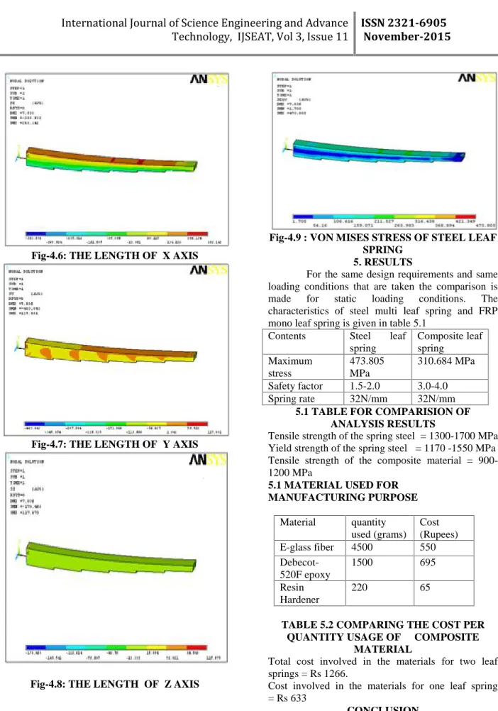
Fig-4.6: THE LENGTH OF X AXIS
Fig-4.7: THE LENGTH OF Y AXIS
Fig-4.8: THE LENGTH OF Z AXIS
Fig-4.9 : VON MISES STRESS OF STEEL LEAF SPRING
5. RESULTS
For the same design requirements and same loading conditions that are taken the comparison is made for static loading conditions. The characteristics of steel multi leaf spring and FRP mono leaf spring is given in table 5.1
Contents Steel leaf spring
Composite leaf spring
Maximum stress
473.805 MPa
310.684 MPa
Safety factor 1.5-2.0 3.0-4.0 Spring rate 32N/mm 32N/mm
5.1 TABLE FOR COMPARISION OF ANALYSIS RESULTS
Tensile strength of the spring steel = 1300-1700 MPa Yield strength of the spring steel = 1170 -1550 MPa Tensile strength of the composite material = 900-1200 MPa
5.1 MATERIAL USED FOR MANUFACTURING PURPOSE
Material quantity used (grams)
Cost (Rupees) E-glass fiber 4500 550
Debecot-520F epoxy
1500 695
Resin Hardener
220 65
TABLE 5.2 COMPARING THE COST PER QUANTITY USAGE OF COMPOSITE
MATERIAL
Total cost involved in the materials for two leaf springs = Rs 1266.
Cost involved in the materials for one leaf spring = Rs 633
The finite element analysis on composite leaf spring is done and the results are now available for concluding the project. The static and modal analysis is done in analysis software ANSYS and they showed safe values for the designed composite leaf spring. So it is conclude that the replacement of heavy weight 7-piece steel leaf spring with light weight mono-leaf spring provides the vehicle with many advantages like the mechanical properties of composites the energy absorption and fatigue resistant characteristics outstanding.
Composite leaf springs absorb energy more readily than steel, giving driver and passengers a more comfortable and quieter journey. The fatigue resistance is greater than with steel, and it is reassuring that in the unlikely event of a facture with composites, the failure would be gradual and identifiable, avoiding the sudden catastrophic failure of metal parts. Composite leaf springs can withstand the harshest environmental conditions to which vehicle suspension systems are subjected. They are non-corrosive and resistant to salt damage in winter climates as well as oil, petrol and acid.
This doesn’t imply that composite leaf springs are indestructible. A close research on the factors leading to failure reveals that composite leaf spring failure could occur due to improper installation, towing the disabled vehicle by using the spring as an attachment point (subjecting the leaf spring to torsion forces for which that is not designed to withstand) and due to heat from the exhaust system where exhaust pipes are placed in closed proximity to leaf spring.
From this it is also concluded that the need for other research is in the area of design modification in the body of the vehicle to avoid the above said ill influences that lead to failure of the composite leaf spring.
REFERENCES
[1] ShivaShankar, Sambagam Vijayarangan– “Mono Composite Leaf Spring for Light Weight Vehicle – Design, End Joint Analysis and Testing” Materials Science Vol.12.N0.3.2006.
[2] Rajendran, I., Vijayarangan, S. “Design and
Analysis of a Composite Leaf Spring” Journal of Institute of Engineers India 82 2002: pp.180–187.
[3] Composite leaf springs and suspension system components for commercial vehicles EPSRC Grant GR/J64238. The University of Reading, white knights.
[4]Bruce.E.Kirkhar, Leo S. Sulliva and Robert E. Bauer, “Development of the liteflux suspension leaf spring”, journal of SAE Tech 820160.
[5]Klkuo Tanabe, Takashi senior and yoshihiro Kajlo, “characteristics of carbon/glass Fiber Reinforced Plastic leaf spring”, Journal of SAE Tech 820403.
[6]Morris C.J, “composite integrated rear suspension”, Journal of composite structures. Corvette leaf springs- wikipedia, the encyclopedia. Material research department composite and material mechanics.Technical article “ leaf spring tech”.
[7]Yu W.J and Kim H.C, “ Double tapered FRP beam for automotive suspension leaf spring”, Journal of composite structures.Design data-fiber glass composites, Publishers Fiberglass Ltd., U.K Literature of epoxy resins, publisher Dr. beck Dobeckot Epoxy resins.SAE manual on Design and application of leaf springs.