Date of publication xxxx 00, 0000, date of current version xxxx 00, 0000. Digital Object Identifier 10.1109/ACCESS.2020.Doi Number
Postfault Operation of Five-Phase Induction
Machine with Minimum Total Losses Under
Single Open-Phase Fault
Abdullah Shawier1, Ayman Samy Abdel-Khalik1, Senior Member, IEEE, Ragi A. Hamdy1,
Senior Member, IEEE, Khaled H. Ahmed2, Senior Member, IEEE, and Shehab Ahmed2, Senior
Member, IEEE
1Department of Electrical Engineering, Alexandria University, 21544, Egypt
2Department of Electronic and Electrical Engineering, Strathclyde University, Glasgow, UK 3CEMSE Division at King Abdullah University of Science and Technology, Saudi Arabia
Corresponding author: Abdullah Shawier (e-mail: [email protected]).
ABSTRACT Five-phase induction machines (FPIM) have attracted notable interest in safety critical applications as well as wind energy generation systems. This is largely due to their additional degrees of freedom that retain the machine starting/running steadily under fault conditions. In the available literature, postfault operation of multiphase machines is typically implemented using two techniques: minimum losses (ML) or maximum torque per ampere (MT) strategies. The optimization embedded into the control strategy, however, mostly addresses minimization of the stator copper loss, while the effect of the rotor loss and core loss are discarded in the optimal current calculation. This paper revisits postfault operation of the FPIM under single open phase fault (1OPF) by including the effect of both rotor loss and core loss on the machine’s optimal current calculation over the full achievable loading range. The proposed searching algorithm, which combines the advantages of both MT and ML techniques, attempts to minimize the total machine losses induced by the current components of both the fundamental 𝛼𝛼𝛼𝛼 and the secondary 𝑥𝑥𝑥𝑥 subspaces. The theoretical findings have been experimentally validated using a 1.5Hp five-phase prototype system.
INDEX TERMS Five-phase induction machine, post fault operation, minimum copper losses, core losses, open phase fault, rotor losses, open phase.
Nomenclature
𝑖𝑖 Current
𝑣𝑣 Voltage
𝜆𝜆 Flux linkage
𝑅𝑅 Winding resistance
𝐿𝐿 Self or magnetizing inductances
𝐿𝐿𝑙𝑙 Leakage inductance
𝜔𝜔 Angular electrical synchronous speed
𝜔𝜔𝑟𝑟 Rotor electrical angular speed
𝑅𝑅𝑐𝑐 Equivalent core loss resistance
𝑠𝑠 slip
𝑝𝑝 Differentiation operator
Subscripts
𝑛𝑛 Subspace order
𝛼𝛼,𝛼𝛼 Fundamental subspace components
𝑥𝑥,𝑥𝑥 Secondary subspace components
𝑠𝑠 Stator 𝑟𝑟 Rotor 𝑚𝑚 Magnetizing 𝑐𝑐 Core Superscripts � Phasor quantity
� Quantities while core loss is discarded
I. INTRODUCTION
The increased interest in multiphase machines has driven researchers to focus their effort on improving their post-fault operation strategies [1, 2]. The most salient characteristic of multiphase machines is their ability to sustain proper performance under an open-phase(s) fault. This feature has
economical and safety implications in many industrial applications that require such high reliability. Automotive, aerospace, ship propulsion and offshore wind energy generation represent key examples of such applications [3-5].
The global interest in sustainability has been a steady driver in the growth of wind energy. Today, wind energy possesses a significant share of the renewable energy mix [6]. Incorporating wind energy into distribution systems may have various benefits like minimizing power losses and increasing efficiency [7-9]. Multiphase machines research directed towards high power and high reliability wind energy systems (WESs) has benefited from the growing interest in wind energy [10, 11]. Machine fault tolerance, which is defined as the ability of the machine to continue running under fault conditions, is possible with multiphase machine drive systems due to their extra degrees of freedom as a consequence of increasing the number of phases. Such features have rendered serious interest in multiphase machines in recent WESs [12, 13].
Postfault operation of different types of multiphase machines with various stator phase numbers under open phase(s) conditions has been studied in the available literature
[14] with the objective of continuous motor operation and ripple-free torque output when two or more healthy phases remain connected. The healthy phases guarantee the creation of a symmetrical rotating magnetic field with the help of different control strategies [15-17]. Optimal current control, under post-fault operation, is generally used to regulate the currents of the remaining healthy phases to satisfy certain optimization criteria including minimum torque ripple, equal line currents, and/or minimum copper loss [15, 18, 19]. The available control techniques are mainly based on controlling current components of the secondary subspace(s), and hence the harmonic and fundamental components are no longer decoupled. Equal stator joule losses postfault strategy, more commonly referred to as maximum torque per ampere scheme, generates the desired symmetrical MMF at equal phase currents. This keeps the machine running at the maximum possible torque for a specific current magnitude. Under the MT scenario, pre-fault rated torque can be obtained under 1OPF if the remaining phase currents are allowed to increase by 38.2% from their rated healthy value. If the current magnitude is limited to the rated value, the machine output torque should be derated to 72.36% of rated output in case of permanent magnet machines, where the direct current component is commonly set to zero [14, 15]. On the other hand, the minimum loss strategy can generate balanced fundamental αβ current components, while ensuring minimum stator copper loss. For rated output torque, the current magnitudes of two out of the four remaining healthy phases increase by 46.8% of their rated values, while the other two phases exceed the rated value by 26.3% [20]. In order to avoid undesirable thermal hotspots inside the stator winding, the machine is derated such that the two phases carrying maximum currents are limited to the machine rated current. The maximum achievable torque will eventually be limited to 68.13% of its rated output [21].
In [22] smooth output torque has been obtained using the MT technique by creating expanded transformation matrices considering the torque and copper loss equations of the fundamental and secondary subspaces. The authors have also proposed a new technique for evaluating the MT characteristics and finding the relevant current references for a five-phase generator under fault conditions with one or
two-phase open fault cases [23]. Postfault operation under
minimum losses is also studied in [14, 24] for multiphase machines with an odd number of phases.
Literature has also demonstrated the utilization of the loss minimizing control scheme based on a lookup table for the
permanent magnet synchronous motor (PMSM) [25]. Loss
minimizing current sets are obtained using the experimental power loss data calculated for different d-axis current and saved in a lookup table. Then, the study was extended by deriving a third-order polynomial, which is used to obtain an approximate solution that is fed to the loss-minimization algorithm [26]. Reference [27] proposed a postfault control strategy for multiphase machines that minimizes stator losses in the entire torque operation range. This scheme has been denoted as full-range minimum loss (FRML) postfault strategy. This study, however, assumes that the effect of the induced rotor current components of the secondary subspaces, as well as the machine core losses have nothing to do with the obtained optimal solution. Nevertheless, this assumption has not been mathematically confirmed in the available literature so far. This assumption was also made assuming that the air gap flux induction corresponding to the secondary subspace can merely be neglected. Although this may be the case for a double layer distributed winding, the same assumption cannot be literally generalized for single layer winding multiphase machines [28]. The latter winding layout is preferably employed for odd phase numbers, where third harmonic injection is commonly used to enhance the machine torque density [28].
This paper extends the study introduced in [27] to single layer winding-based FPIM to account for the effect of rotor losses for both fundamental and secondary subspaces as well as the machine core losses for postfault optimal current calculation of a FPIM. A new postfault scheme, denoted as full-range minimum total loss (FRMTL) postfault strategy, has therefore been introduced. The core losses effect is considered in the fundamental αβ frame using a lumped shunt equivalent core loss resistance. The core loss estimation will be carried out while the machine is assumed to be driven using conventional indirect rotor field-oriented control (IRFOC)
similar to the three-phase case introduced in [29]. The
theoretical findings of this study have been experimentally validated using a 1.5Hp FPIM.
II. MACHINE MATHEMATICAL MODELING
This section introduces the mathematical model of a five-phase induction machine with multiple subspaces based on the conventional 𝑑𝑑𝑑𝑑 model [30]. It also shows how the machine losses are estimated under the commonly employed indirect rotor field-oriented control (IRFOC) technique [24]. The total
machine losses represent the objective function for the employed optimization problem in this study. In this context, the core loss effect is modeled using a shunt equivalent resistance parallel to the magnetizing inductance of the fundamental subspace [29].
A. CONVENTIONAL DQ MODEL OF FIVE-PHASE IM
Five phase induction machines are commonly modeled using
conventional 𝑑𝑑𝑑𝑑modelling with two decoupled subspaces
[30]. This conventional model considers only the dominant harmonics of both fundamental and secondary subspaces, while the effect of saturation, space harmonics, skin effect and hysteresis are commonly discarded.
In this modeling approach, the phase quantities 𝑓𝑓𝑠𝑠𝑎𝑎→𝑒𝑒, where𝑓𝑓 ∈{ 𝑣𝑣,𝑖𝑖,𝜆𝜆}, are decomposed into three orthogonal subspaces �𝑓𝑓𝑠𝑠𝛼𝛼𝛼𝛼 ; 𝑓𝑓𝑠𝑠𝑥𝑥𝑥𝑥 ; 𝑓𝑓𝑠𝑠0�=𝑇𝑇.𝑓𝑓𝑠𝑠𝑎𝑎→𝑒𝑒using the decoupl-ing transformation matrix given by (1) [31]. The fundamental αβ subspace represents the torque producing subspace, while the secondary 𝑥𝑥𝑥𝑥 subspace contributes mainly to additional machine copper losses and the zero-sequence subspace is eliminated for a star connected stator.
𝑇𝑇=25 ⎣ ⎢ ⎢ ⎢ ⎡ 10 1 0 0.5 cos𝛿𝛿 −sin𝛿𝛿 cos 3𝛿𝛿 −sin 3𝛿𝛿 0.5 cos 2𝛿𝛿 −sin 2𝛿𝛿 cos 6𝛿𝛿 −sin 6𝛿𝛿 0.5 cos 3𝛿𝛿 −sin 3𝛿𝛿 cos 9𝛿𝛿 −sin 9𝛿𝛿 0.5 cos 4𝛿𝛿 −sin 4𝛿𝛿 cos 12𝛿𝛿 −sin 12𝛿𝛿 0.5 ⎦⎥ ⎥ ⎥ ⎤ (1)
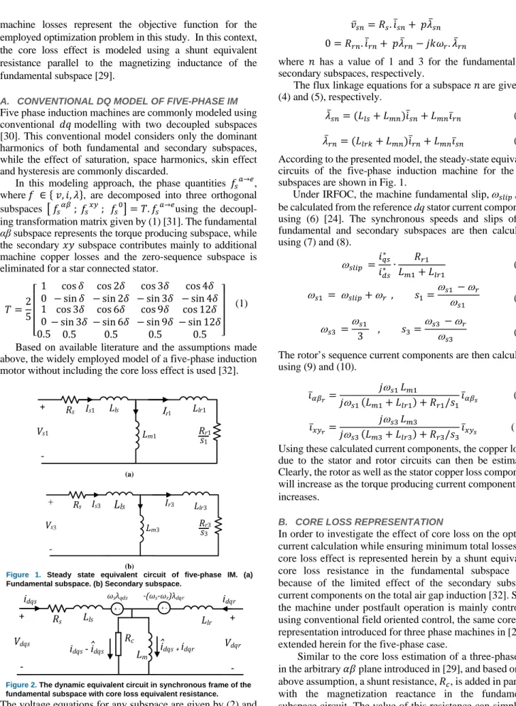
Based on available literature and the assumptions made above, the widely employed model of a five-phase induction motor without including the core loss effect is used [32].
Rs Lls Lm1 Llr1 Rr1 Is1 Ir1 + Vs1 -s1 (a) Rs Lls Lm3 Llr3 Is3 Ir3 + Vs3 -Rr3 s3 (b)
Figure 1. Steady state equivalent circuit of five-phase IM. (a)
Fundamental subspace. (b) Secondary subspace.
Rs Lls Rc Lm Llr idqs idqr + Vdqs -ωsλqds -(ωs-ωr)λdqr idqs - i
ˆ
dqs iˆ
dqs+ idqr + Vdqr -+ - +-Figure 2. The dynamic equivalent circuit in synchronous frame of the
fundamental subspace with core loss equivalent resistance.
The voltage equations for any subspace are given by (2) and (3);
𝑣𝑣̅𝑠𝑠𝑠𝑠=𝑅𝑅𝑠𝑠.𝚤𝚤̇̅𝑠𝑠𝑠𝑠+ 𝑝𝑝𝜆𝜆̅𝑠𝑠𝑠𝑠 (2) 0 =𝑅𝑅𝑟𝑟𝑠𝑠.𝚤𝚤̇̅𝑟𝑟𝑠𝑠+ 𝑝𝑝𝜆𝜆̅𝑟𝑟𝑠𝑠− 𝑗𝑗𝑗𝑗𝜔𝜔𝑟𝑟.𝜆𝜆̅𝑟𝑟𝑠𝑠 (3)
where 𝑛𝑛 has a value of 1 and 3 for the fundamental and
secondary subspaces, respectively.
The flux linkage equations for a subspace 𝑛𝑛are given by (4) and (5), respectively.
𝜆𝜆̅𝑠𝑠𝑠𝑠= (𝐿𝐿𝑙𝑙𝑠𝑠+𝐿𝐿𝑚𝑚𝑠𝑠)𝚤𝚤̇̅𝑠𝑠𝑠𝑠+𝐿𝐿𝑚𝑚𝑠𝑠𝚤𝚤̅𝑟𝑟𝑠𝑠 (4)
𝜆𝜆̅𝑟𝑟𝑠𝑠= (𝐿𝐿𝑙𝑙𝑟𝑟𝑙𝑙+𝐿𝐿𝑚𝑚𝑠𝑠)𝚤𝚤̇̅𝑟𝑟𝑠𝑠+𝐿𝐿𝑚𝑚𝑠𝑠𝚤𝚤̅𝑠𝑠𝑠𝑠 (5)
According to the presented model, the steady-state equivalent circuits of the five-phase induction machine for the two subspaces are shown in Fig. 1.
Under IRFOC, the machine fundamental slip,ω𝑠𝑠𝑙𝑙𝑠𝑠𝑠𝑠 , can be calculated from the reference dq stator current components using (6) [24]. The synchronous speeds and slips of the fundamental and secondary subspaces are then calculated using (7) and (8). ω𝑠𝑠𝑙𝑙𝑠𝑠𝑠𝑠 =𝑖𝑖𝑖𝑖𝑞𝑞𝑠𝑠∗ 𝑑𝑑𝑠𝑠∗ ∙ 𝑅𝑅𝑟𝑟1 𝐿𝐿𝑚𝑚1+𝐿𝐿𝑙𝑙𝑟𝑟1 (6) ω𝑠𝑠1 = ω𝑠𝑠𝑙𝑙𝑠𝑠𝑠𝑠+ω𝑟𝑟 , 𝑠𝑠1=ω𝑠𝑠1 −ω𝑟𝑟 ω𝑠𝑠1 (7) ω𝑠𝑠3 =ω𝑠𝑠1 3 , 𝑠𝑠3= ω𝑠𝑠3 −ω𝑟𝑟 ω𝑠𝑠3 (8)
The rotor’s sequence current components are then calculated using (9) and (10). 𝚤𝚤̅𝛼𝛼𝛼𝛼𝑟𝑟= 𝑗𝑗ω𝑠𝑠1 𝐿𝐿𝑚𝑚1 𝑗𝑗ω𝑠𝑠1 (𝐿𝐿𝑚𝑚1+𝐿𝐿𝑙𝑙𝑟𝑟1) +𝑅𝑅𝑟𝑟1/𝑠𝑠1𝚤𝚤̅𝛼𝛼𝛼𝛼𝑠𝑠 (9) 𝚤𝚤̅𝑥𝑥𝑥𝑥𝑟𝑟= 𝑗𝑗ω𝑠𝑠3 𝐿𝐿𝑚𝑚3 𝑗𝑗ω𝑠𝑠3 (𝐿𝐿𝑚𝑚3+𝐿𝐿𝑙𝑙𝑟𝑟3) +𝑅𝑅𝑟𝑟3/𝑠𝑠3𝚤𝚤̅𝑥𝑥𝑥𝑥𝑠𝑠 (10)
Using these calculated current components, the copper losses due to the stator and rotor circuits can then be estimated. Clearly, the rotor as well as the stator copper loss components will increase as the torque producing current component, 𝑖𝑖𝑞𝑞𝑠𝑠, increases.
B. CORE LOSS REPRESENTATION
In order to investigate the effect of core loss on the optimal current calculation while ensuring minimum total losses, the core loss effect is represented herein by a shunt equivalent core loss resistance in the fundamental subspace only because of the limited effect of the secondary subspace current components on the total air gap induction [32]. Since the machine under postfault operation is mainly controlled using conventional field oriented control, the same core loss representation introduced for three phase machines in [29] is extended herein for the five-phase case.
Similar to the core loss estimation of a three-phase IM in the arbitrary 𝛼𝛼𝛼𝛼plane introduced in [29], and based on the above assumption, a shunt resistance,𝑅𝑅𝑐𝑐, is added in parallel with the magnetization reactance in the fundamental subspace circuit. The value of this resistance can simply be estimated from the conventional no-load test, as explained in
[32]. The dynamic equivalent circuit for the fundamental subspace is shown in Fig 2, where 𝑖𝑖𝑑𝑑𝑞𝑞𝑠𝑠 and 𝚤𝚤̂𝑑𝑑𝑞𝑞𝑠𝑠 are the dq stator current components with and without considering core loss, respectively [33].
The core loss equation in the synchronous 𝑑𝑑𝑑𝑑 frame, according to [29], and after accounting for the number of phases, is given by (11). 𝑃𝑃𝑐𝑐𝑐𝑐𝑟𝑟𝑒𝑒=52 ω𝑠𝑠2𝐿𝐿 𝑚𝑚12 𝑅𝑅𝑐𝑐 �𝚤𝚤̇̂𝑑𝑑𝑠𝑠 2 +𝚤𝚤̇̂𝑑𝑑𝑠𝑠𝑖𝑖𝑑𝑑𝑟𝑟+𝚤𝚤̇̂𝑞𝑞𝑠𝑠2+𝚤𝚤̇̂𝑞𝑞𝑠𝑠𝑖𝑖𝑞𝑞𝑟𝑟� (11)
Considering IRFOC, the relations given by (12) will hold. 𝑖𝑖𝑞𝑞𝑟𝑟=−𝚤𝚤̇̂𝑞𝑞𝑠𝑠 and 𝑖𝑖𝑑𝑑𝑟𝑟 = 0 (12)
Then, (11) can be simplified as in (13). 𝑃𝑃𝑐𝑐𝑐𝑐𝑟𝑟𝑒𝑒=52 ω𝑠𝑠2𝐿𝐿 𝑚𝑚12 𝑅𝑅𝑐𝑐 �𝚤𝚤̇̂𝑑𝑑𝑠𝑠 2 � (13)
It is noted that under IRFOC, the core loss depends directly on the direct current component and indirectly on the torque producing component, where the stator frequency,ω𝑠𝑠, is a function of the quadrature current component, as indicated by (6). Therefore, at rated reference speed, the change in core loss with mechanical loading may be neglected, as will be shown in the results section. Moreover, the relation between the total machine losses and the torque producing stator current component, 𝑖𝑖𝑞𝑞𝑠𝑠, could be represented by a load torque dependent component (rotor and stator copper losses) shifted by an approximately constant loss component representing the core losses, for a given direct current component and reference speed.
III. PROPOSED FRMTL POSTFAULT STRATEGY
This section introduces the block diagram of the proposed postfault controllers and the corresponding optimal current calculation.
A. CONTROLLER BLOCK DIAGRAM
The full block diagram of the employed postfault controller of a FPIM based on IRFOC is shown in Fig. 3. In the proposed
controller, the current components 𝑖𝑖𝑑𝑑𝑠𝑠∗ and 𝑖𝑖𝑞𝑞𝑠𝑠∗ , which represent the field and torque reference stator current components, respectively [34], are derived based on the required reference flux level and speed error. The stator fundamental current components,𝑖𝑖𝛼𝛼𝛼𝛼∗ , are then obtained from the reference dq current components through Park’s transformation using the estimated slip (6) and the rotor angular speed. Based on the proposed optimization technique introduced in the subsequent subsections, the secondary subspace sequence current components, 𝑖𝑖𝑥𝑥𝑥𝑥∗ are obtained from the reference current components, 𝑖𝑖𝛼𝛼𝛼𝛼∗ , using an optimized gain matrix ensuring minimum total machine losses. These calculated fundamental and secondary reference current components are compared with the measured sequence components (using (1)), and the corresponding sequence voltage components are derived using two pairs of PR controllers. Needless to say, under postfault operation, the optimal machine currents are no longer balanced [14]. However, the PR controllers can successfully track unbalanced reference currents without sophisticated axis transformation [35].
B. POSTFAULT REFERENCE OPTIMAL CURRENTS
Under open-phase conditions, the sequence current components 𝑖𝑖𝛼𝛼𝛼𝛼 and 𝑖𝑖𝑥𝑥𝑥𝑥 are no longer decoupled. The maximum allowable value of the fundamental subspace 𝑖𝑖𝛼𝛼𝛼𝛼 current depends on the employed postfault scenario to ensure a suitable torque/flux control [27]. On the other hand, the 𝑖𝑖𝑥𝑥𝑥𝑥 current components are coupled by a gain matrix to the fundamental currents based on the selected optimization criteria as well as the applied load torque. After fault occurrence (assuming a fault in phase a), one degree of freedom will be lost. Based on (1), the relation between 𝑖𝑖𝛼𝛼 and 𝑖𝑖𝑥𝑥 is governed by (14).
𝑖𝑖𝑥𝑥=−𝑖𝑖𝛼𝛼 (14)
Furthermore, sequence current components can be expressed under postfault operation as a function 𝑖𝑖𝛼𝛼𝛼𝛼 as in [27];
αβxy / abcde Trans. Vα* ,Vβ* Vx* ,Vy* 0 Vabcde PWM
IM
ia ib ic id ie ω + PR iα* , iβ* iα , iβ ωs* Vα* , Vβ* + PR ix* , iy* ix , iy ωs* Vα* , Vβ* PI + ω* ω IRFOC dq/αβ Trans. ids* iqs* Өs* Tk ωs* iα ,iβ iα* , iβ* ix* , iy* abcde/ αβxy0 Trans. iabcde iα , iβ ix , iy⎣ ⎢ ⎢ ⎢ ⎡𝑖𝑖𝑖𝑖𝛼𝛼𝛼𝛼 𝑖𝑖𝑥𝑥 𝑖𝑖𝑥𝑥 𝑖𝑖0⎦ ⎥ ⎥ ⎥ ⎤ =𝑇𝑇𝑙𝑙�𝑖𝑖𝑖𝑖𝛼𝛼𝛼𝛼�, 𝑇𝑇𝑙𝑙= ⎣ ⎢ ⎢ ⎢ ⎡ 10 −1 𝑗𝑗1 0 0 1 0 𝑗𝑗2 0⎦⎥ ⎥ ⎥ ⎤ (15)
where, 𝑇𝑇𝑙𝑙 is the optimization matrix.
The proposed optimization technique calculates the optimum 𝑇𝑇𝑙𝑙based on the reference quadrature current component, 𝑖𝑖𝑞𝑞𝑠𝑠∗ ,
(torque producing current component) through the MATLAB optimizer fmincon. The scalar gains 𝑗𝑗1 and 𝑗𝑗2 are obtained such that the total machine loss is minimized over the full achievable loading range. It is worth mentioning that the conventional ML scenario corresponds to zero values for both 𝑗𝑗1 and 𝑗𝑗2 over the full loading range, while the conventional
MT mode can be enabled by setting them to 0 and 0.236, respectively. These two scenarios are the two well-established techniques that are mostly suggested in postfault operation. The former technique is employed under low torque values, while the latter represents the employed strategy at higher loads. As clarified in the introduction section, the FRML strategy [27] has been proposed to combine the advantages of both techniques over the full loading range, and upon which the proposed FRMTL will be derived.
C. POSTFAULT OPTIMIZATION TECHNIQUE.
The mathematical representation of the FRMTL strategy is derived by optimizing the machine total loss given by (16) subjected to the constraints given by (17). It is worth mentioning that in all available literature, the optimization problem is formulated based on the stator losses only. 𝑃𝑃𝑙𝑙𝑐𝑐𝑠𝑠𝑠𝑠= 𝑅𝑅𝑠𝑠 �|𝑖𝑖𝑠𝑠𝑠𝑠|2 5 𝑠𝑠=1 +𝑅𝑅𝑟𝑟 �|𝑖𝑖𝑟𝑟𝑠𝑠|2 5 𝑠𝑠=1 +𝑃𝑃𝑐𝑐𝑐𝑐𝑟𝑟𝑒𝑒 =52 ⎝ ⎜ ⎛𝑅𝑅𝑠𝑠�|𝑖𝑖𝛼𝛼𝑠𝑠| 2+�𝑖𝑖 𝛼𝛼𝑠𝑠�2+ |𝑖𝑖𝑥𝑥𝑠𝑠|2+�𝑖𝑖𝑥𝑥𝑠𝑠�2� +𝑅𝑅𝑟𝑟1�|𝑖𝑖𝛼𝛼𝑟𝑟|2+�𝑖𝑖𝛼𝛼𝑟𝑟�2� +𝑅𝑅𝑟𝑟3�|𝑖𝑖𝑥𝑥𝑟𝑟|2+�𝑖𝑖𝑥𝑥𝑟𝑟�2� ⎠ ⎟ ⎞ +𝑃𝑃𝑐𝑐𝑐𝑐𝑟𝑟𝑒𝑒 (16) • 𝑐𝑐1: 𝑖𝑖𝑥𝑥𝑠𝑠= −𝑖𝑖𝛼𝛼𝑠𝑠 (𝑖𝑖𝑎𝑎= 0), (17) • 𝑐𝑐2: 𝑖𝑖𝛼𝛼𝑠𝑠=𝐼𝐼∠0,𝑖𝑖𝛼𝛼𝑠𝑠=𝐼𝐼∠90 , • 𝑐𝑐3: ‖𝑖𝑖ℎ 𝑠𝑠‖𝑚𝑚𝑎𝑎𝑥𝑥 ≤ 𝐼𝐼𝑠𝑠𝑟𝑟𝑎𝑎𝑟𝑟𝑒𝑒𝑑𝑑 • 𝑐𝑐4: ∑5𝑠𝑠=1𝑖𝑖𝑠𝑠𝑠𝑠= 0 • 𝑖𝑖ℎ
𝑠𝑠 refers to the remaining healthy stator phase currents • 𝐼𝐼=�𝑖𝑖𝑑𝑑𝑠𝑠2 +𝑖𝑖
𝑞𝑞𝑠𝑠2 represents the current amplitude • 𝐼𝐼𝑠𝑠𝑟𝑟𝑎𝑎𝑟𝑟𝑒𝑒𝑑𝑑refers to the rated stator phase current
After a fault occurs in phase a, for example, the subspace currents are no longer decoupled, as indicated by the first constraint in (17). The second constraint theoretically ensures ripple free torque production by the fundamental subspace. While, the third constraint enforces the optimizer to limit the all remaining healthy phases to rated current value. Finally, the last constraint ensures that the sum of the remaining
currents is zero [14]. Thus, the optimized phase currents remain below their rated value while achieving the lowest possible total losses over the entire torque range. Therefore, the efficiency is increased and minimum total loss with maximum achievable torque range is extended until the loading hits the MT operating point. In contrast to
conventional MT and ML, the optimization matrix 𝑇𝑇𝑙𝑙
coefficient varies with 𝑖𝑖𝑞𝑞𝑠𝑠∗ which is calculated offline for the full loading range. The estimated 𝑇𝑇𝑙𝑙 coefficients are saved into a lookup table against the reference 𝑖𝑖𝑞𝑞𝑠𝑠∗ and used for real time implementation.
The flowchart shown in Fig. 4 briefly explains the optimization process. For a given reference speed value ω𝑟𝑟𝑒𝑒𝑟𝑟 , the optimization starts by defining the rated 𝑖𝑖𝑑𝑑𝑠𝑠∗ value as well as the machine rated current. Then, the algorithm calculates the maximum allowable quadrature current component under healthy condition, 𝑖𝑖𝑞𝑞𝑠𝑠𝑚𝑚𝑎𝑎𝑥𝑥, based on the peak rated current, 𝐼𝐼𝑠𝑠𝑟𝑟𝑎𝑎𝑟𝑟𝑒𝑒𝑑𝑑. Starting from the no-load point (𝑖𝑖𝑞𝑞𝑠𝑠∗ = 0), the
fundamental subspace currents 𝑖𝑖𝛼𝛼𝛼𝛼 for both rotor and stator are calculated similar to the healthy case, while satisfying (17), based on the machine slip speed calculated from (6) [14]. The synchronous speeds and rotor slip speeds for both subspaces are determined using (7) and (8). For a given 𝑇𝑇𝑙𝑙 matrix (obtained from the optimization algorithm), the sequence components of the rotor currents are calculated based on (9) and (10). The core losses could then be obtained using (13). The MATLAB function𝑓𝑓𝑚𝑚𝑖𝑖𝑛𝑛𝑐𝑐𝑓𝑓𝑛𝑛 computes the coefficients of 𝑇𝑇𝑙𝑙 such that (16) is minimized. The algorithm sweeps over the allowable range for 𝑖𝑖𝑞𝑞𝑠𝑠∗ , where the maximum current value corresponds to the MT operating point. The maximum allowable 𝑖𝑖𝑞𝑞𝑠𝑠∗ during a fault will depend on the 𝑖𝑖𝑑𝑑𝑠𝑠⁄𝑖𝑖𝑞𝑞𝑠𝑠, ratio as will be clarified in the results section.
No C3 satisfied No Start id , Israted , ωref fmincon found a solution Increase iq* Yes iq* = 0 calculate iαβs, ωslip1, ωslip3, iαβr Store k1 , k2 in Tk Calculate Iabcde & PLoss
iq* > Iqmax
No Yes
Yes End
(a)
(b)
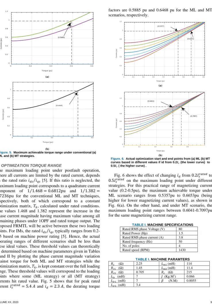
Figure. 5. Maximum achievable torque range under conventional (a)
ML and (b) MT strategies.
D. OPTIMIZATION TORQUE RANGE
The maximum loading point under postfault operation, where all currents are limited by the rated current, depends on the rated ratio 𝑖𝑖𝑑𝑑𝑠𝑠⁄𝑖𝑖𝑞𝑞𝑠𝑠 [5]. If this ratio is neglected, the maximum loading point corresponds to a quadrature current
component of 1 1.468⁄ = 0.6812pu and 1 1.382⁄ =
0.7236pu for the conventional ML and MT techniques, respectively, both of which correspond to a constant optimization matrix, 𝑇𝑇𝑙𝑙, calculated under rated conditions. The values 1.468 and 1.382 represent the increase in the phase current magnitude having maximum value among all remaining phases under 1OPF and rated torque output. The proposed FRMTL will be active between these two loading points. For IMs, the rated 𝑖𝑖𝑑𝑑𝑠𝑠⁄𝑖𝑖𝑞𝑞𝑠𝑠 typically ranges from 0.2-0.5 based on machine power rating [5]. Hence, the actual operating ranges of different scenarios shall be less than these ideal values. These threshold values can theoretically be determined based on machine parameters given in Tables I and II by plotting the phase current magnitude variation against torque for both ML and MT strategies while the optimization matrix, 𝑇𝑇𝑙𝑙, is kept constant over the full loading range. These threshold values will correspond to the loading points where some (ML strategy) or all (MT strategy) currents hit rated value. Fig. 5 shows that for peak rated current 𝐼𝐼𝑠𝑠𝑟𝑟𝑎𝑎𝑟𝑟𝑒𝑒𝑑𝑑= 5.4 𝐴𝐴 and 𝑖𝑖𝑑𝑑= 2.3 𝐴𝐴, the derating torque
factors are 0.5885 pu and 0.6468 pu for the ML and MT scenarios, respectively.
(a)
(b)
Figure. 6. Actual optimization start and end points from (a) ML (b) MT
curves based in different values if id from 0.2𝑰𝑰𝒓𝒓 (the lower curve) to 0.5𝑰𝑰𝒓𝒓 ( the higher curve) .
Fig. 6 shows the effect of changing 𝑖𝑖𝑑𝑑 from 0.2𝐼𝐼𝑠𝑠𝑟𝑟𝑎𝑎𝑟𝑟𝑒𝑒𝑑𝑑 to 0.5𝐼𝐼𝑠𝑠𝑟𝑟𝑎𝑎𝑟𝑟𝑒𝑒𝑑𝑑 on the maximum loading point under different
strategies. For this practical range of magnetizing current value (0.2-0.5pu), the maximum achievable torque under ML scenario ranges from 0.5357pu to 0.6653pu (being higher for lower magnetizing current values), as shown in Fig. 6(a). On the other hand, and under MT scenario, the maximum loading point ranges between 0.6041-0.7097pu for the same magnetizing current range.
TABLE I. MACHINE SPECIFICATIONS
Rated RMS phase Voltage (V) 80 Rated Power (Hp) 1.5 Rated RMS phase current (A) 3.8 Rated frequency (Hz) 50
No. of poles 4
Rated speed (RPM) 1430 TABLE I. MACHINE PARAMTERS
𝑅𝑅𝑠𝑠 (Ω) 2.25 𝐿𝐿𝑚𝑚1 (mH) 114 𝑅𝑅𝑟𝑟1 (Ω) 1.45 𝐿𝐿𝑚𝑚3 (mH) 11.4 𝑅𝑅𝑟𝑟3 (Ω) 0.705 𝑅𝑅𝑐𝑐 (Ω) 215 𝐿𝐿𝑙𝑙𝑠𝑠 (mH) 7 𝐽𝐽 (Kg.M2) 0.066 𝐿𝐿𝑙𝑙𝑟𝑟1 (mH) 7 𝛼𝛼 (N.M) 0.0055 𝐿𝐿𝑙𝑙𝑟𝑟3 (mH) 3.4 0 0.2 0.4 0.6 0.8 Torque (pu) 0 0.2 0.4 0.6 0.8 1 1.2 Currents (pu) (0.5885) 0 0.2 0.4 0.6 0.8 Torque (pu) 0 0.2 0.4 0.6 0.8 1 Cur rents (pu) (0.6468) 0 0.1 0.2 0.3 0.4 0.5 0.6 0.7 0.8 Torque (pu) 0 0.2 0.4 0.6 0.8 1 1.2 Currents (pu) (0.6653) (0.5357) 0 0.2 0.4 0.6 0.8 Torque (pu) 0 0.2 0.4 0.6 0.8 1 1.2 Currents (pu) (0.6401) (0.7097)
IV. EXPERIMENTAL SETUP
The prototype five-phase induction machine with the ratings and parameters given in Tables I and II is employed to validate the proposed postfault controller. The FPIM is built by rewinding a standard 4-pole three-phase machine using the technique given in [36]. The five-phase machine has two pole pairs, each pole pair has 14 coils with different number of turns per coil but with the same total number of turns per phase.
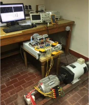
The machine parameters are identified using the technique given in [28]. The dc-link is emulated by a 300V programmable DC supply. The FPIM is coupled to a separately excited DC generator which acts as a mechanical load. The employed DSP board is TMS320F28379D Launchpad which has up to 169 GPIO, dual CPU with main frequency 200 MHz, 24 PWM channels, four independent ADCs modules with a 16-bit/12bit resolution up to 12/24 channels, and 3 DAC 12-bit resolution to display any internal signal. Two 600V, 20A, IRAMY20UP60B inverter modules operating at 10kHz switching frequency are used to construct the two-level five-phase inverter by utilizing only five legs of the available six legs. The controller is opto-isolated from the power converter through fast switching opto-couplers 6N137. The software used to deploy the programs is Code Composer Studio software EDI under Simulink/Matlab platform. Five hall-effect current sensors (LEM) are used for phase current measurement, while speed measurement is done using a tachogenerator. The whole experimental setup is shown in Fig. 7.
Figure 7. Experimental FPIM Setup.
Figure 8. Variation of k2 with mechanical loading.
V. EXPERIMENTAL AND SIMULATION RESULTS
In this section, the proposed FRMTL postfault strategy is experimentally validated using the prototype system given in the previous section. A comparison is also carried out with conventional MT and ML scenarios with constant optimal gain matrices.
In the given results, the reference speed is set to 1000 rpm, while the direct current component is set to the rated magnetizing current of 2.3A. By running the optimization algorithm over the full torque range, the calculated optimization matrices, 𝑇𝑇𝑙𝑙, for different loading torque values illustrate that the optimum value for 𝑗𝑗1 is always zero, while 𝑗𝑗2 varies from zero under ML operating mode to 0.236 for
the MT point, which represents the maximum loading point, as shown in Fig. 8.
The optimizer has also been run by considering only the stator losses. Interestingly enough, no difference has been found in the optimum gains over the whole torque range. This conclusion may be explained by (10). For conventional ML, the stator loss is minimized when 𝑖𝑖𝑥𝑥𝑠𝑠= 0. From (10), by setting 𝑖𝑖𝑥𝑥𝑠𝑠= 0, the corresponding rotor current component 𝑖𝑖𝑥𝑥𝑟𝑟 will also be zero, which minimizes the copper losses in both rotor and stator circuits. Hence, including/discarding the effect of the rotor and core losses on the optimal current calculations under postfault operation has nothing to do with the optimal reference currents derived in the available literature.
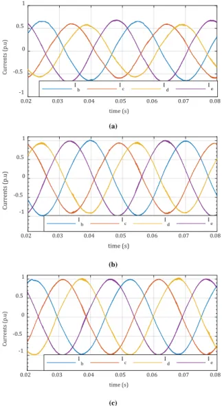
The experimental and simulation results for phase currents are compared in Fig. 9 under conventional ML, conventional MT, and proposed FRMTL, respectively. The continuous curves represent simulation results and experimental readings are represented by the discrete points. Under low torque values, the ML mode represents the optimal postfault operation with 𝑗𝑗2 = 0 until the two phases carrying maximum current magnitude hit the rated current value (1pu), which corresponds to a torque value of 0.5885 pu, as explained in section III.D. Fig. 10(a) shows an example for the optimal phase currents for a load torque value less than 0.5885 pu (conventional ML mode). As the machine loading increases, the optimization problem shows an increasing value for 𝑗𝑗2, while the two phases carrying
0 0.1 0.2 0.3 0.4 0.5 0.6 0.7 Torque (pu) 0 0.05 0.1 0.15 0.2 0.25 k 2
maximum currents will be limited to 1pu, and the current magnitude of the other two phases increases with mechanical loading. Fig. 10(b) shows an example for the optimal phase currents for an operating point within this loading range. At the maximum loading point, the four healthy currents will be
equal in magnitude to 1pu while𝑗𝑗2 reaches a maximum
value of 0.236, which takes place at a loading torque point equal to 0.6468 pu. This latter case is depicted in Fig. 10(c). If machine overloading is allowed, the gain 𝑗𝑗2 saturates at this maximum value, which ensures equal current magnitudes for all the remaining healthy phases.
(a)
(b)
(c)
Figure 9. Loading effect on optimal phase currents over the entire
torque range using (a) ML, (b) MT, and (c) Proposed FRMTL strategies.
(a)
(b)
(c)
Figure 10. Loading effect on optimal phases currents of the proposed
technique at (a) k2=0 (b) 0< k2 <0.236 (c) k2=0.236.
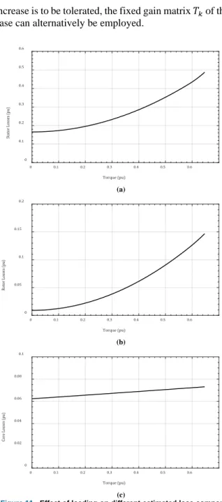
The variation of different estimated loss components with load torque is shown in Fig. 11, while the machine efficiency under different criteria is depicted in Fig. 12. Fig. 11 shows that the most dominant loss component is the stator copper loss. Besides, the core loss slightly increases with the mechanical loading, as indicated in (13).
It is clear that for a five-phase case, the operating range of the proposed FRMTL is relatively limited, while the machine efficiency under conventional ML is clearly better. On the other hand, for the six-phase case, this range extends over a wider range (0.35-0.6pu) [5].Hence, thejustification to apply FRMTL in the six-phase case seems more valuable. To elaborate on this point, Fig. 13 shows the variation of the RMS values of the optimal currents if the ML technique is employed for the prototype five-phase machine over the same loading range. Clearly, two out of the four phase currents exceed rated current (1pu) for the loading range from 0.5885-0.6468pu. Nevertheless, this current increase is limited to only 6.2% above rated value at the maximum achievable load torque of 0.6468pu. If this slight current
0 0.1 0.2 0.3 0.4 0.5 0.6 Torque (pu) 0 0.2 0.4 0.6 0.8 1 Currents (pu) Ia Ib Ic I d Ie Ib m I c m Id m Ie m 0 0.1 0.2 0.3 0.4 0.5 0.6 Torque (pu) 0 0.2 0.4 0.6 0.8 1 Currents (pu) Ia Ib Ic I d Ie Ib m I c m Id m Ie m 0 0.1 0.2 0.3 0.4 0.5 0.6 Torque (pu) 0 0.2 0.4 0.6 0.8 1 Currents (pu) I a Ib Ic I d Ie Ib m I c m Id m Ie m 0.02 0.03 0.04 0.05 0.06 0.07 0.08 time (s) -1 -0.5 0 0.5 1 Currents (p.u) I b Ic Id Ie 0.02 0.03 0.04 0.05 0.06 0.07 0.08 time (s) -1 -0.5 0 0.5 1 Cur rents (p.u) I b Ic Id Ie 0.02 0.03 0.04 0.05 0.06 0.07 0.08 time (s) -1 -0.5 0 0.5 1 Currents (p.u) I b Ic Id Ie
increase is to be tolerated, the fixed gain matrix 𝑇𝑇𝑙𝑙 of the ML case can alternatively be employed.
(a)
(b)
(c)
Figure 11. Effect of loading on different estimated loss components.
(a) Stator losses. (b) Rotor losses. (c) Core losses.
Figure 12. Experimental efficiency versus load torque curve under
different postfault strategies.
Figure 13. Phase currents under conventional ML strategy.
VI. CONCLUSION
This paper investigates the effect of considering the rotor loss and core loss components in the optimal current calculation of a five-phase induction machine during postfault operation with one phase open, while the total machine losses is minimized. The available literature only considers the stator loss in calculation of the optimal currents assuming a double layer distributed stator winding. For machines with a single layer stator winding, which is preferably employed in five-phase machines, the induced rotor secondary sequence current components are no longer zero. Nevertheless, the modified optimization problem introduced in this work showed similar performance to what is presented in the literature regardless of considering the rotor loss and core loss. Furthermore, limiting the phases currents to their rated values over the entire torque range was shown to be insignificant for the five-phase machine case when compared with the traditional ML technique; the latter corresponds to only 6.2% increase in the magnitude of phase currents above the rated value for the same maximum achievable torque.
REFERENCES
[1] K. Yanagihara, D. T. Vu, N. K. Nguyen, J. Gong, E. Semail, and T. J. dos Santos Moraes, "Fault-tolerant Control for 7-phase Non-sinusoidal Permanent Magnet Machines with One Opened Phase," in 2019 International Symposium on Electrical and Electronics Engineering (ISEE), 2019, pp. 292-297.
[2] M. Priestley, M. Farshadnia, and J. E. Fletcher, "FOC transformation for single open-phase faults in the five-phase open-end winding topology," IEEE Trans. Ind. Electron., vol. 67, no. 2, pp. 842-851, 2019.
[3] A. Salem and M. Narimani, "A Review on Multiphase Drives for Automotive Traction Applications," IEEE Trans. Transportation Electrification, vol. 5, no. 4, pp. 1329-1348, Dec. 2019.
[4] I. Vasile, E. Tudor, M. Popescu, C. Dumitru, L. Popovici, and I. C. Sburlan, "Electric Drives with Multiphase Motors as a Better Solution for Traction Systems," in 2019 11th International Symposium on Advanced Topics in Electrical Engineering (ATEE), 2019: IEEE, pp. 1-5. 0 0.1 0.2 0.3 0.4 0.5 0.6 Torque (pu) 0 0.1 0.2 0.3 0.4 0.5 0.6 Stat or Losse s (pu) 0 0.1 0.2 0.3 0.4 0.5 0.6 Torque (pu) 0 0.05 0.1 0.15 0.2 Rotor Losse s (pu) 0 0.1 0.2 0.3 0.4 0.5 0.6 Torque (pu) 0 0.02 0.04 0.06 0.08 0.1 Cor e Losse s (pu) 0.2 0.4 0.6 0.8 1 Torque (pu) 68 70 72 74 Efficiency (%) MT ML FRMTL 0 0.1 0.2 0.3 0.4 0.5 0.6 Torque (pu) 0 0.2 0.4 0.6 0.8 1 1.2 Currents (pu) I a Ib I c Id I e 1.062
[5] A. S. Abdel-Khalik, M. S. Hamad, A. M. Massoud, and S. A. Ahmed, "Postfault operation of a nine-phase six-terminal induction machine under single open-line fault," IEEE Trans. Ind. Electron., vol. 65, no. 2, pp. 1084-1096, Feb. 2018.
[6] K. Chandramohan, S. Padmanaban, R. Kalyanasundaram, and F. Blaabjerg, "Modeling of five-phase, self-excited induction generator for wind mill application," Electric Power Components and Systems, vol. 46, no. 3, pp. 353-363, 2018.
[7] J. Rodas, H. Guzmán, R. Gregor, and F. Barrero, "Model predictive current controller using Kalman filter for fault-tolerant five-phase wind energy conversion systems," in 2016 IEEE 7th International Symposium on Power Electronics for Distributed Generation Systems (PEDG), 2016, pp. 1-6.
[8] A. A. Daoud, S. S. Dessouky, and A. A. Salem, "Control scheme of PMSG based wind turbine for utility network connection," in 2011 10th International Conference on Environment and Electrical Engineering, 2011, pp. 1-5.
[9] S. Rhaili, A. Abbou, S. Marhraoui, N. El Hichami, and A. V. Hemeyine, "Robustness investigation of Vector Control of Five-phase PMSG based Variable-Speed Wind Turbine under faulty condition," in 2018 Renewable Energies, Power Systems & Green Inclusive Economy (REPS-GIE), 2018, pp. 1-6.
[10] N. K. Mishra, Z. Husain, and M. R. Khan, "D, Q reference frames for the simulation of multiphase (six phase) wound rotor induction generator driven by a wind turbine for disperse generation," IET Electric Power Applications, vol. 13, no. 11, pp. 1823-1834, 2019. [11] K. Chinmaya and G. K. Singh, "Performance evaluation of multiphase
induction generator in stand-alone and grid-connected wind energy conversion system," IET Renewable Power Generation, vol. 12, no. 7, pp. 823-831, 2018.
[12] O. Abdel-Rahim, H. Funato, H. Abu-Rub, and O. Ellabban, "Multiphase wind energy generation with direct matrix converter," in 2014 IEEE International Conference on Industrial Technology (ICIT), 2014: IEEE, pp. 519-523.
[13] A. Pantea et al., "Fault-tolerant control of a low-speed six-phase induction generator for wind turbines," IEEE Transactions on Industry Applications, vol. 55, no. 1, pp. 426-436, Jan.-Deb. 2019. [14] J.-R. Fu and T. A. Lipo, "Disturbance-free operation of a multiphase
current-regulated motor drive with an opened phase," IEEE Trans Ind. Appl., vol. 30, no. 5, pp. 1267-1274, Sept.-Oct. 1994,.
[15] S. He, J. Huang, and M. Kang, "Post-fault operation for five-phase induction machines under single-phase open using symmetrical components," in 2018 IEEE Applied Power Electronics Conference and Exposition (APEC), 2018, pp. 218-222.
[16] S. C. Rangari, H. M. Suryawanshi, and M. Renge, "New fault-tolerant control strategy of five-phase induction motor with four-phase and three-phase modes of operation," Electronics, vol. 7, no. 9, p. 159, 2018.
[17] H. M. Eldeeb, A. S. Abdel-Khalik, and C. M. Hackl, "Postfault full torque–speed exploitation of dual three-phase IPMSM drives," IEEE Trans. Ind. Electron., vol. 66, no. 9, pp. 6746-6756, Sept. 2019. [18] M. B. Guzman, O. Gomozov, X. Kestelyn, F. Barrero, N. K. Nguyen,
and E. Semail, "Model predictive optimal control considering current and voltage limitations: Real-time validation using OPAL-RT technologies and five-phase permanent magnet synchronous machines," Mathematics and Computers in Simulation, vol 158, pp. 148-161, Apr. 2019.
[19] H. M. Eldeeb, A. S. Abdel-Khalik, J. Kullick, and C. M. Hackl, "Pre-and Postfault Current Control of Dual Three-Phase Reluctance Synchronous Drives," IEEE Trans. Ind. Electron., vol. 67, no. 5, pp. 3361-3373, May 2020.
[20] A. Hosseyni, R. Trabelsi, M. F. Mimouni, and A. Iqbal, "Fault tolerant vector controlled five-phase permanent magnet synchronous motor drive with an open phase," in 2018 15th International Multi-Conference on Systems, Signals & Devices (SSD), 2018, pp. 780-784. [21] S. Karugaba, G. Wang, O. Ojo, and M. Omoigui, "Dynamic and steady-state operation of a five phase induction machine with an open stator phase," in 2008 40th North American Power Symposium, 2008, pp. 1-8.
[22] P. Zhao, G. Yang, and Y. Li, "Fault-tolerant control strategy for five-phase permanent magnetic synchronous motor under single five-phase open-circuit fault condition," in Zhongguo Dianji Gongcheng
Xuebao(Proceedings of the Chinese Society of Electrical Engineering), 2011, vol. 31, no. 24, pp. 68-76.
[23] O. Fall, J. F. Charpentier, N.-K. Nguyen, and P. Letellier, "Maximum torque per ampere control strategy of a 5-phase PM generator in healthy and faulty modes for tidal marine turbine application," in 2014 International Power Electronics and Application Conference and Exposition, 2014, pp. 468-473.
[24] A. Tani, M. Mengoni, L. Zarri, G. Serra, and D. Casadei, "Control of multiphase induction motors with an odd number of phases under open-circuit phase faults," IEEE Trans. Power Electron., vol. 27, no. 2, pp. 565-577, Feb. 2012.
[25] J. Lee, K. Nam, S. Choi, and S. Kwon, "A lookup table based loss minimizing control for FCEV permanent magnet synchronous motors," in 2007 IEEE Vehicle Power and Propulsion Conference, 2007, pp. 175-179.
[26] J. Lee, K. Nam, S. Choi, and S. Kwon, "Loss minimizing control of PMSM with the use of polynomial approximations," in 2008 IEEE Industry Applications Society Annual Meeting, 2008, pp. 1-9. [27] F. Baneira, J. Doval-Gandoy, A. G. Yepes, O. López, and D.
Pérez-Estévez, "Control strategy for multiphase drives with minimum losses in the full torque operation range under single open-phase fault," IEEE Trans. Power Electron., ol. 32, no. 8, pp. 6275-6285, Aug. 2017.
[28] A. S. Abdel-Khalik, M. I. Daoud, S. Ahmed, A. A. Elserougi, and A. M. Massoud, "Parameter identification of five-phase induction machines with single layer windings," IEEE Transactions on Industrial Electronics, vol. 61, no. 10, pp. 5139-5154, Oct. 2014. [29] Y. Liu and A. M. Bazzi, "A general analytical three-phase induction
machine core loss model in the arbitrary reference frame," IEEE Trans. Ind. Appl., vol. 53, no. 5, pp. 4210-4220, Sept.-Oct. 2017. [30] L. A. Pereira, C. C. Scharlau, L. F. A. Pereira, and J. F. Haffner,
"General model of a five-phase induction machine allowing for harmonics in the air gap field," IEEE Trans. Energy Conversion, vol. 21, no. 4, pp. 891-899, Dec. 2006.
[31] H. Xu, W. Huang, F. Bu, H. Liu, and X. Lin, "Control of five-phase dual stator-winding induction generator with an open phase," IEEE Trans. Ind. Electron., vol. 66, no. 1, pp. 696-706, Jan. 2019. [32] A. S. Abdel-Khalik, S. Ahmed, and A. M. Massoud, "Steady-state
equivalent circuit of five-phase induction machines with different stator connections under open-line conditions," IEEE Trans. Ind. Electron., vol. 63, no. 8, pp. 4651-4662, Aug. 2016.
[33] Y. Liu and A. M. Bazzi, "Frequency, load, and flux impacts on induction machine copper and core losses in the qd0-frame," in 2017 IEEE Energy Conversion Congress and Exposition (ECCE), 2017, pp. 776-781.
[34] F. Wilczyński, M. Morawiec, P. Strankowski, J. Guziński, and A.
Lewicki, "Sensorless field oriented control of five phase induction motor with third harmonic injection," in 2017 11th IEEE International Conference on Compatibility, Power Electronics and Power Engineering (CPE-POWERENG), 2017: IEEE, pp. 392-397. [35] D. G. Holmes, B. P. McGrath, and S. G. Parker, "Current regulation
strategies for vector-controlled induction motor drives," IEEE Trans. Ind. Electron., vol. 59, no. 10, pp. 3680-3689, Oct. 2012.
[36] A. S. Abdel-Khalik, A. M. Massoud, and S. Ahmed, "Application of standard three-phase stator frames in prime phase order multiphase machine construction," IEEE Trans. Ind. Electron., vol. 66, no. 4, pp. 2506-2517, Apr. 2019.
Abdullah Shawierreceived the B.Sc. degree in
electrical engineering from Alexandria University, Alexandria, Egypt, in 2016. He is currently a demonstrator with the Electrical Engineering Department, Faculty of Engineering, Alexandria University, Alexandria, Egypt. His current research interests include electric drives, battery chargers, electric vehicles, and renewable energy systems.
Ayman S. Abdel-Khalik (SM’12) received the B.Sc. and M.Sc. degrees in electrical engineering from Alexandria University, Alexandria, Egypt, in 2001 and 2004, respectively, and the Ph.D. degree in electrical engineering from Alexandria University, and Strathclyde University, Glasgow, U.K., in 2009, under a dual channel program. He is currently a Professor with the Electrical Engineering Department, Faculty of Engineering, Alexandria University, Alexandria, Egypt. He serves as an Associate Editor of IEEE Transactions on Industrial Electronics and IET Electric Power Applications Journal. Also, he serves as the Executive Editor of Alexandria Engineering Journal. His current research interests include electrical machine design and modelling, electric drives, energy conversion, and renewable energy.
Ragi A. Hamdy (SM’19) received B.Sc. and
M.Sc. on 91 and 94 from Alexandria University, Egypt, and Ph.D. on 99 from Heriot-Watt University, UK. He is currently a Professor with the Electrical Engineering Department, Faculty of Engineering, Alexandria University, Alexandria, Egypt. His current research interests include electric machines, Electric Drives, and power electronics.
Khaled H. Ahmed (M’09, SM’12) received the
B.Sc. (Hons.) and M.Sc. degrees from Alexandria University, Egypt in 2002 and 2004, respectively. He received the Ph.D. degree in power electronics applications from the University of Strathclyde, UK, 2008. He was appointed as a Professor at Alexandria University, Egypt since 2019. Currently, Dr Ahmed is a Reader in Power Electronics at the University of Strathclyde, UK. He is a senior member of the IEEE Power Electronics and Industrial Electronics societies. Dr Ahmed has published more than 110 technical papers in refereed journals and conferences as well as a published textbook entitled ‘High Voltage Direct Current Transmission: Converters, Systems and DC Grids’, a book chapter contribution, and a PCT patent PCT/GB2017/051364. His research interests are renewable energy integration, high power converters, offshore wind energy, DC/DC converters, HVDC, and smart grids.
Shehab Ahmed (SM'12) received the B.Sc.
degree in electrical engineering from Alexandria University, Alexandria, Egypt, in 1999, and the M.Sc. and Ph.D. degrees from the Department of Electrical and Computer Engineering, Texas A&M University, College Station, TX, USA, in 2000 and 2007, respectively. He was with Schlumberger Technology Corporation, Houston, TX, USA, from 2001 to 2007, developing downhole mechatronic systems for oilfield service products. He was with Texas A&M University at Qatar from 2007 to 2018 (currently on leave). He is currently Professor and Program Chair of the Electrical and Computer Engineering Program in the CEMSE Division at King Abdullah University of Science and Technology, Saudi Arabia. His research interests include mechatronics, solid-state power conversion, electric machines, and drives.