Union College
Union | Digital Works
Honors Theses
Student Work
6-2016
Control System for 3D Printable Robotic Hand
Htoo Wai Htet
Union College - Schenectady, NY
Follow this and additional works at:
https://digitalworks.union.edu/theses
Part of the
Biotechnology Commons
,
Investigative Techniques Commons
,
Orthotics and
Prosthetics Commons
, and the
Robotics Commons
This Open Access is brought to you for free and open access by the Student Work at Union | Digital Works. It has been accepted for inclusion in Honors Theses by an authorized administrator of Union | Digital Works. For more information, please [email protected].
Recommended Citation
Htet, Htoo Wai, "Control System for 3D Printable Robotic Hand" (2016).Honors Theses. 160. https://digitalworks.union.edu/theses/160
Control System for 3D Printable Robotic Hand
Htoo Wai Htet
∗March 18, 2016
∗
Abstract
Humanoid robotics is a growing area of research due to its potential applications in orthosis and pros-thesis for human beings. With the currently available technologies, the most advanced robotic hands used in prosthetics or robotics can cost from $11,000 to $90,000, making it inaccessible to the general population of amputees and robotics hobbyists. Most of the features provided by these expensive technologies are su-perfluous to many users, creating a great gap in cost and services between users and technology. Using the emerging 3D printing technology, my project is to construct a 3D printed robotic hand that can reproduce as many basic functionalities of the advanced expensive hands, while minimizing the cost. The project in-volves choosing a feasible 3D printed design plan, assembly of the mechanical and electrical components of the robotic hand, the design and implementation of the software interface for intuitive user control of the hand and ease of integrability to existing robotic systems. This new hand will allow mimicking, versatile gripping, human-recognizable gestures, feedback controlled force exertion, and a ROS integrated software interface. This project will further allow students at Union to extend their research in social robotics and human-computer interface by incorporating the inexpensive robotic hand.
1
Report Summary
Motivated by the high cost of advanced humanoid robotic hand, the goal of this project is to construct an inexpensive 3D printed robotic hand that can reproduce as many of the functionalities of the advanced hand, while minimizing the cost. Since the project is completed as the combination of Electrical Engineering and Computer Science projects, it is divided into two design tasks. The electrical engineering design task is to create a system of electronic sensors and actuators for the robotic hand. The computer science design task is to create a modular software that will control the electronic components in the robotic hand using Robotic Operating System (ROS) framework.
The electrical engineering design task began with an investigation on a variety of existing 3D printable hand models. A set of design requirements were then formulated based on the desired functionality of the hand. The functionalities include mimicking, versatile gripping, human-recognizable gestures, feedback controlled force exertion. Once a feasible 3D model was chosen, different electronic sensors and actuators were explored, ensuring that the design requirements for size, power consumption, sensing range and price were met. An appropriate controller that enables ROS integration was then chosen for mimicking.
The computer science design task began with the decomposition of the desired functionalities of the hand into a state machine. Since the basic building blocks of a ROS system are message passing and services between nodes, the state machine was used to convert to the node architecture of ROS, determining which node will keep track of the states, how it will communicate with other nodes via message passing, and the data types of messages are considered. Based on the controller that is chosen, respective translator node – that translates controller messages to ones that can be interpreted by the actuators of the hand – was implemented.
The final outcome of this project will be a functional robotic hand that will serve not only as a robotic component that can be attached to a larger robot, but also as a gateway for research in social robotics and human compute interface. Since the control software of the robotic hand is designed to be very modular, i.e. it can be adapted to different types of controllers, various upgrades can also be made, such as integrating the micro-controller and the computer onto a single-board computer like RaspberryPi. In the future, the mechanical components can also be expanded into an arm or even full human torso and head.
Contents
1 Report Summary 3 2 Introduction 10 2.1 The Problem . . . 10 2.2 The Objective . . . 11 2.3 Report Outline. . . 143 Background and Related Work 15 3.1 3D Printing and Hand Architecture. . . 15
3.2 Related Projects on 3D Printed Hands . . . 17
3.3 ROS . . . 17 3.4 Outcomes . . . 20 4 Design Requirements 21 4.1 Size . . . 23 4.2 Gripping . . . 23 4.3 Gestures . . . 23 4.4 Response Time. . . 24 4.5 Cost . . . 24 4.6 ROS Integration . . . 24
4.7 Closed Loop Force Control. . . 25
5 Design Alternatives 26 5.1 Structure . . . 26
5.2 Electrical Components . . . 27
5.3 Software Design Decision . . . 27
6.1 Overview. . . 28 6.2 Structure . . . 28 6.3 Electrical Components . . . 29 6.3.1 Micro-Controllers. . . 29 6.3.2 Motors . . . 29 6.3.3 Sensors . . . 29 6.4 Software Choices . . . 30
6.4.1 Closed-loop control simulation . . . 30
6.4.2 ROS service and message passing . . . 30
6.4.3 ROSserial . . . 30
6.4.4 ROS-MYO driver . . . 31
7 Final Design and Implementation 31 7.1 Overview. . . 31
7.2 Structure and Assembly . . . 32
7.3 Electrical components . . . 33 7.3.1 Schematics. . . 33 7.3.2 Sensor Calibration . . . 34 7.3.3 Servo Calibration . . . 35 7.3.4 Porting to Perfboard . . . 35 7.4 Software design . . . 36
7.4.1 Finite State Machine . . . 36
7.4.2 ROS implementation . . . 37
7.4.3 Serial Communication . . . 39
7.4.4 Control Algorithm . . . 40
7.4.5 Mimic . . . 41
8.1 Size . . . 44
8.2 Gripping . . . 44
8.3 Gestures . . . 45
8.4 Response Time. . . 46
8.5 Closed Loop Force Control. . . 46
8.6 ROS Integration . . . 47
8.7 Cost . . . 47
9 Production Schedule 47 10 Cost Analysis 48 11 User’s Manual 49 11.1 Getting ROS Running. . . 49
11.2 Calibration . . . 49 11.3 Replacement . . . 50 11.3.1 3D Printed Part . . . 50 11.3.2 Servo . . . 50 11.3.3 Tension Cable . . . 50 11.3.4 Sensor . . . 51 12 Conclusion 51 13 Future Work 52
List of Figures
1 Shadow robotic hand showing its dexterity with fragile light bulb [4].. . . 11
2 Block diagram showing a brief system overview and its hardware and software scope.. . . . 12
3 Hand design of Borghesan’s team, showing how each tension cable controls lateral or curling movement of the finger [5]. . . 13
4 Hand design of Pizarro’s team, showing its skin (black) and exposed bone (white) structure [6]. 15 5 Static to articulated hand model using Cal`ı’s transformation metho [7]. . . 16
6 De Laurentis’ hand model showing non-assembly joints and points for embedded compo-nents insertion [8]. . . 16
7 Figures of open source 3D hand models. . . 18
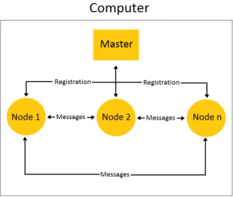
8 A block diagram showing the how nodes and messages work in ROS. . . 19
9 Block diagram of a closed-looped control system showing forward path and feedback path . 25 10 Top view of the assembled hand with the forearm open, showing the servos inside . . . 31
11 Figures of silicone finger tip . . . 32
12 Short-tail FSR from Pololu citepololu-sensor . . . 33
13 Schematics of the prototype of the robotic hand system sketched using Fritzing . . . 34
14 Schematics of the perfboard designs sketched in Fritzing . . . 35
15 State diagram of the finite state machine designed for the robotic hand . . . 36
16 Node diagram of the finite state machine implemented in ROS, showing how nodes commu-nicate with via message passings . . . 38
17 Block diagrams describing how the Firmata protocol grants full control of the Arduino. . . . 39
18 Resistance vs. Force curve of the short-tail FSRs from Pololu [21], showing logarithmic relation 40 19 The 3D printed hand performing a gripping action showing its capability to meet the weight limit criterion . . . 44
20 Figures of five human understandable gestures performed by the 3D printed hand while in “Gesture” state . . . 45
21 Testing closed loop force control via threshold detection using sensor feedback form the in-dex finger . . . 46
List of Tables
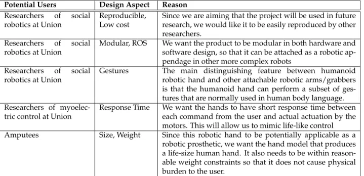
1 Design Constraints based on specific users and the reasoning for each constraint . . . 21
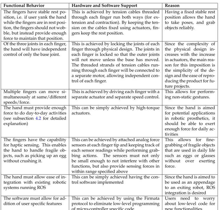
2 Functional decomposition of the hand showing how each function is supported by hard-ware/software and the reason behind imposing each behavioral restriction. . . 22
3 Structural design alternatives between the CAD models, describing the benefits and draw-backs of each model. . . 26
4 Design alternatives between electrical components, describing the benefits and drawbacks of each component. . . 27
2
Introduction
Humanoid robotics is a growing area of research due to its potential applications in orthosis and prosthe-sis for human beings. Replicating the functionality and behaviors of a complex biological systems using rigid mechanical components can be a challenging task, and the human hand is no exception. Made up of 29 bones, 34 muscles and 123 ligaments [1], the human hand is a very complex system that poses a challenging research question to humanoid robotics on how to reconstruct it with mechanical components. With cur-rently available technologies, the most advanced robotic hand used in prosthetics and humanoid robotics can perform most of the tasks that a human hand can perform, ranging from grabbing objects of various shapes and weight distribution, manipulating with tools to perform complex tasks, picking up small and fragile object such as a coin, an egg or even a needle. Attempts have been made to perform even complex tasks such as playing a piano [2,3]. With each research attempt improving the hand, the humanoid robotic hand is gradually approaching the dexterity of a human hand.
2.1
The Problem
The main application for humanoid robotic hand is in robotics and prosthesis. With currently available technology, the most advanced robotic hand can cost from $11,000 to $90,000, making it inaccessible to the general population of robotic hobbyists or amputees. Moreover, many of the features provided by these expensive technologies are developed for research purposes in an attempt to replicate human hand, but can be superfluous to most users who simply wish to perform only a small subset of a normal human’s functionalities without paying a great deal of money. This creates a great gap in cost and services between users and technology, posing a financial burden to many users, especially child amputees whose prosthetic have to adjust to the growing hand. Figure1shows the most advanced robotic hand, costing∼$98,000, that can reproduce all degrees of freedom of a human hand, developed by the Shadow Robot Company in London [4]. Actuated by air muscles with over 100 sensors, the figure demonstrates the hand handing a fragile light bulb with just three fingers.
With the emergence of 3D printing technology, most parts of the robotic hand can be easily 3D printed, bringing the cost of the product to less than $500. An average user without any technical knowledge can
Figure 1: Shadow robotic hand showing its dexterity with fragile light bulb [4].
easily order a print for the mechanical parts required for the hand and easily assemble it. This would allow not only average-income amputees to have access to cheaper electronic prosthetics, but also aspir-ing robotics students to be able to study the most advanced technologies without havaspir-ing to pay a large sum of money. However, the existing open-source 3D models of the hand are aimed for amputees, and thus, they are designed to be actuated by the remaining part of the amputees’ hand, rather than using electro-mechanical actuators. The project aims to solve this problem by adapting a 3D model that allows for addition of actuators and servos, and designing a modular software that allows the user to intuitively control the robotic hand and integrate into existing robotic systems.
2.2
The Objective
The goal of this project is to replicate most of the functionalities of an advanced robotic hand using 3D printed parts. To achieve this, a 3D printed robotic hand needs to be first assembled from scratch. This hand will mimic the functionalities of the advanced hands without compromising the price. Given the project time frame of 20 weeks, the subset of advanced functionalities that we have chosen to mimic are: fast motor response, high force gripping, forming simple human hand gestures, feedback controlled force exertion and integrability. Some of the functionalities that were chosen to omit are: accurate finger positioning, lateral movement of the fingers, higher degrees of freedom in finger joints.
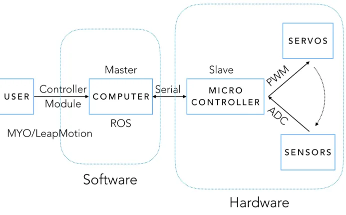
Figure 2: Block diagram showing a brief system overview and its hardware and software scope.
Figure2shows the block diagram of robotic hand system, indicating its hardware and software com-ponents. On the top level, the user controls the hand via a controller module. This can be as simple as keystrokes from a computer keyboard, or a MYO – an armband that can send accelerometer and elec-tromyographic signals from the human arm, or a LeapMotion – a sensor module with a camera and IR sensors that can virtualize the fingers and joints of a human hand. These signals are passed to the computer that will be running the control software for the hand implemented in ROS framework. The software then sends serial messages that can be interpreted by the micro-controller. All these fall under the software scope of the project as indicated in Figure2. According to the serial messages received from the computer, the micro-controller will send relevant PWM signals to the actuators, which affect the sensor values that are read by the analog to digital converter (ADC) of the microcontroller. These are sent back to the computer
again as serial messages. This will be the hardware scope of the project.
In order to print a physical model of the hand, a 3D CAD model is required. With the availability of open source CAD models, the design stage of this CAD model is bypassed. Extensive research into the existing open source models resulted in the choice of a CAD design that best fits our functional requirements. Details of each CAD design model with their benefits and drawbacks are discussed in section5under Table3.
To mimic a high force fast response by the fingers, the fingers need to be precisely actuated by DC motors with encoders, or by servos motors. The motors create finger motion via the tension cables that are threaded through each finger, so the tension cables also need to withstand the high torque by the motors. Figure3shows threaded finger with tension cables from Borghesan’s team [5]. Their team used five tension cables to achieve most life-like actuation. In this project, we only use tension cablesT4andT3seen in the figure for simple extension and contraction of finger.
Figure 3: Hand design of Borghesan’s team, showing how each tension cable controls lateral or curling movement of the finger [5].
The choice between the motors also determines the choice of sensors and feedback system. This is because DC motors can sense the amount of torque being applied by sensing the current flowing through
them, while servo motors need additional mechanism for sensing.The feedback system needs to know how much force that the motors are exerting on the fingers so that the object being grabbed is not crushed.
The degrees of freedom that is allowed by the 3D model of choice determines the types of gestures that can be formed by the hand. Since the physical design allows only the curling of each finger, but not the lateral movements, a subset of gestures that require crossing of fingers cannot be performed. However, the hand should be able to perform gestures that require curling of independent fingers. Detailed reasons for these design requirements and alternatives can be found in Table2and3on page22and26.
The control algorithm that will be implemented for the feedback-controlled force exertion will be deter-mined by the choice of actuator and sensor. An algorithm similar to the PID algorithm, which minimizes the error between the output signal and the input signal, is aimed to be implemented.
Finally, to make the entire hand system easily integratable into an existing larger robotic system, we will need to design our software to be implemented within the ROS framework, which is the popular software framework for many robotic systems. By making the design of the software to be modular, the hand can not only be controlled by different types of controllers, but also be improved with additional functionalities based on user’s needs.
With the availability of this new inexpensive robotic part, we hope that more research projects related to social robotics and gesture control or human computer interface will emerge at Union. In the future this robotic hand project can even be expanded to a study of humanoid robotics involving other human body parts.
2.3
Report Outline
In the remainder of this report, we will first introduce to some background information in section3, cover-ing the 3D printcover-ing technology that was used in this project, related literatures on 3D printcover-ing non-assembly joints, existing open-source 3D printed hand projects, followed by a discussion on ROS and the expected outcome from this project. Section4will discuss the design requirements in details, exploring each design aspect for different potential users, functional decomposition of the hand and how each function is sup-ported by hardware and software, followed by the design specification of each function. Section5discusses
design alternatives that are considered for the structure, electrical components and software. In section6
the reason behind choices that were made from the different design alternatives are discussed. Section7
elaborates on the final design of the system separated into hardware and software. In section8, the testing criteria and results are discussed, along with changes made. Section10shows the cost breakdown of each component of the hand, followed by section12,11and13covering conclusion, user’s manual and future work.
3
Background and Related Work
3.1
3D Printing and Hand Architecture
Most Researchers aiming to 3D print humanoid hand are motivated by the capability of 3D printing tech-nology that allows for the hand to be printed without any form of assembly.
Pizarro’s team [6] have done a project on designing a 3D model of a humanoid hand that requires no assembly. They used a Objet Connex350 3D printer, which uses PolyJet multi-material 3D printing technology. This is a form of additive manufacturing process that uses a UV curable polymer that is cured with each passing of the print. Since the printer allows for multi-material printing, both the ”bone” and ”skin” of the hand can be printed using rigid VeroWhitePlus resin and rubber-like TangoBlack resin.
Figure 4: Hand design of Pizarro’s team, showing its skin (black) and exposed bone (white) structure [6]. A literature search also revealed related research on 3D printing various types of non-assembly joints for human hand and other articulated models. Cal`ı’s research [7] explores methods of transforming static model meshes into 3D printable articulated models that require no assembly. However, this method is
found to be useful only for ”posing” models as seen in Figure5. De Laurentis’ [8] article explores how to design 3D printable models more directly. However, this model includes slots for inserting hall-effect sensors, loading the springs for tension, and threading a cable for contraction as seen in Figure6. A more mechanical design oriented approach can also be found in Borghesan’s paper [5]. His model is completely tendon-driven, and requires five tendons per finger. Figure3showed his model.
Figure 5: Static to articulated hand model using Cal`ı’s transformation metho [7].
Figure 6: De Laurentis’ hand model showing non-assembly joints and points for embedded components insertion [8].
hands can also be found. Raymond’s research [9] involves 3D printing a four-finger hand with just a single actuator. This underactuated gripper can grip a wide variety of object geometries. Raphael’s hand design [10] uses a compliant material to form an underactuated anthropomorphic hand. Due to its flexible palm design, the thumb of this hand has the ability to touch the tips of all other four fingers.
3.2
Related Projects on 3D Printed Hands
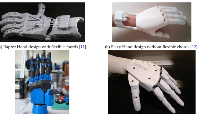
Open source 3D printed hand designs are widely available due to its potential impact in inexpensive pros-thetics. The most notable design is the Raptor hand [11] developed by e-NABLE, shown in Figure7a. This design serves as a static prosthetics that can be actuated by the forearm of the amputee. A variant of this design, also developed by e-NABLE is called a Flexy Hand [12] shown in Figure7b. This hand uses flexible hinges that retract when the forearm muscle is relaxed, eliminating the need for flexible chords.
Other 3D printable active prosthetics designs include one developed by the Open Hand project [13]. This is a compact design that uses small DC motors as actuators, shown in Figure7c. A less compact design using servo motors is developed as a humanoid robotic project called InMoov Project [14], as shown in Figure7d. A variant of the InMoov project’s hand design, which allows more degree of freedom, is also developed by a company named Looqui [15]. Detailed discussion on the pros and cons of each of these designs can be found in section5.
3.3
ROS
The Robot Operating System (ROS) is an open source framework for writing robot softwares. As stated in Quigley paper’s [16], ROS is not an operating system in the traditional sense of process management and scheduling; rather, it provides a structured communications layer above the host operating systems of a heterogenous compute cluster. The paper also describes in details the goals of ROS, the implementation and several common use cases of robotic software development. A brief overview of ROS follows.
(a) Raptor Hand design with flexible chords [11]. (b) Flexy Hand design without flexible chords [12].
(c) Open Hand Project’s compact hand design that uses DC motors [13].
(d) Assembled hand of InMoov’s 3D printable Humanoid Robotic Project [14]
Figure 7: Figures of open source 3D hand models.
With the growth in scale and scope of robotics, writing software for robots become increasingly difficult. Since the implementation of such complex levels of software (which may contain driver-level softwares to higher-level softwares for perception, planning, abstract reasoning and beyond) is a challenging task for a single individual, laboratory, or institution, ROS was built from the ground up to encourage collabora-tive robotics software development. This allows for experts from one laboratory, who are specialized in mapping indoor environments, to contribute a world-class system for producing maps, while experts from another laboratory who are developing planning algorithms to make use of the same mapping software. Developed in 2007, areas of ROS now include a master coordination node, publishing or subscribing to data streams: images, stereo, laser, control, actuator, contact, etc., multiplexing information, node creation and destruction, and beyond. Widely used ROS packages include perception, face recognition, gesture recognition, motion tracking, mobile robotics, and more.
Figure 8: A block diagram showing the how nodes and messages work in ROS.
Figure8shows how the nodes and messages function inside ROS. The ROS Master provides naming and registration services to the rest of the nodes in the ROS system. It tracks publishers and subscribers to topics. The role of the Master is to enable individual ROS nodes to locate one another. A node is essentially an executable file within a ROS package. ROS nodes use a ROS client library to communicate with other nodes. Nodes can publish or subscribe to a Topic. Topics are named buses over which nodes exchange messages. Topics have anonymous publish/subscribe semantics, which decouples the production of infor-mation from its consumption. In general, nodes are not aware of who they are communicating with. Nodes communicate with each other by publishing messages to topics. A message is a simple data structure, com-prising typed fields. Standard primitive types (integer, floating point, boolean, etc.) are supported, as are arrays of primitive types.
The relevance of ROS to the robotic hand project arises from goals of the project: modularity and ease of control. The robotic hand is aimed to serve as modular component: it can be operated as a stand-alone system or as an appendage to a more complex robotic system. Having the robotic hand operate as a ROS node will allow the hand to easily integrate into a larger robotic system also running ROS.
3.4
Outcomes
One of the main outcomes expected of this project is the impact on robotics research at Union College. The aim of this project is to reduce the cost of a robotic hand system so that it can be employed in conducting research related to social robotics and humanoid robotics. Since Union College is already largely involved in social robotic research, incorporating the inexpensive robotic hand, will expand the research questions asked. Examples include “is it easier for a social robot with humanoid hand to approach humans for help?” and “how can a robot that can perform hand gestures interact with humans?”. Moreover, since the hand is controlled via user interaction with a controller module, it is also hoped to expand research in human computer interaction.
This project also has positive economic and health impacts on society. Many existing robotic prosthetics limbs are very costly, featuring superfluous functionalities. Since the robotic hand is 3D printed, it can be adapted to use as an inexpensive active prosthetic. Since the control of the hand can be done through electromyographic (EMG) signals, an amputee can control the hand effortlessly through EMG signals from other limbs or muscles.
Since the project makes extensive use of 3D printing technology and electromyographic signals, it is also expected to encourage future research projects in designing a better 3D CAD model, or developing a better EMG signal gathering and processing equipment. It is also aimed to promote future interdisciplinary research projects in robotics, humanoid robotics, human-computer interface and neuroscience.
There are also certain ethical impacts related to the use of the product as active prosthetics. Even though efforts have been made to ensure that software malfunctions are prevented, there is still a possibility that the hand may perform movements that are not intended by the user’s commands. This raises a question of liability when the hand performs actions harmful to others.
4
Design Requirements
Based on the potential users of the robotic hand, the design requirements for this project are listed as follow. Table1shows the aspects of design that are limited based on each potential user, and the reasoning behind such restriction. Although the table seems to imply that each user is limited to particular design aspects, in reality, it should be kept in mind that having size and weight constraint not only applies to amputees, but also to researchers who want to use the product as an attachable robotic component.
Potential Users Design Aspect Reason
Researchers of social robotics at Union
Reproducible, Low cost
Since we are aiming that the project will be used in future research, we would like it to be easily reproduced by other researchers.
Researchers of social robotics at Union
Modular, ROS We want the product to be modular in both hardware and software design, so that it can be attached as a robotic ap-pendage in other more complex robots
Researchers of social robotics at Union
Gestures The main distinguishing feature between humanoid
robotic hand and other attachable robotic arms/grabbers is that the humanoid hand can perform a subset of ges-tures that are normally used in human body language. Researchers of
myoelec-tric control at Union
Response Time We want the hands to have short response time between each command from the user and actual actuation by the motors. This will allow us to mimic life-like control
Amputees Size, Weight Since this robotic hand to be potentially applicable as a
robotic prosthetic, we want the hand model that produces a life-size human hand. It also needs to be within reason-able weight constraints so that it does not cause physical burden to the user.
Table 1: Design Constraints based on specific users and the reasoning for each constraint
After a function decomposition, we have listed the behavior requirements that we would like our robotic hand to perform as follows. Table2shows each behavior requirement along with how it will be supported via hardware/software, and the reason behind imposing this behavioral requirement. Detailed description of the main design requirements, are discussed in each subsection following the tables.
Functional Behavior Hardware and Software Support Reason
The fingers have stable rest po-sition, i.e. if user yank the hand while the fingers are in rest posi-tion, the fingers should not wob-ble, but instead provide enough force to maintain that position.
This is achieved by tension cables threaded through each finger run both ways (for ex-tension and contraction). By keeping the ten-sion on the cables fixed using actuators, fin-gers keep the rest position.
Having a fixed stable rest position allows the hand to take poses, and grab objects reliably.
Of the three joints in each finger, the hand will have independent control of only the base joint.
This is achieved by locking the joints of each finger through physical design. The joints in each finger is locked so that the outer joints will not move unless the base has moved. The threaded strands of tension cables run-ning through each finger will be connected to a separate motor, allowing independent con-trol of each finger.
Since the complexity of the physical design in-creases with the increase in actuators, the main rea-son for this imposition is the simplicity of the de-sign and the ease of repro-ducing the product for fu-ture projects.
Multiple fingers can move si-multaneously at same/different speeds/force.
This is achieved by driving each finger with a separate actuator and separate speed control.
This allows for perform-ing non-static gestures. The hand must provide enough
force to do day-to-day activities (see subsection 4.2 for detailed explanation)
This can be simply achieved by high-torque actuators.
Since the hand is aimed for potential applications in robotic prosthetics, it should be able to exert enough force for daily ac-tivities
The fingers have the capability for haptic sensing. This enables the hand to handle fragile ob-jects, such as picking up an egg without crushing it.
This can be achieved by attached analog force sensors at each finger tip and keeping track of each sensor readings while performing grab-bing actions. The sensors must not only be small enough to not interfere with other functions, but also provide sensing forces in within range specified above
This allows for fine-grabbing of fragile objects that are used in daily life such as eggs or glasses without over exerting force.
The hand must allow ease of in-tegration with existing robotic systems running ROS
This can be simply achieved having the con-trol software implemented
Since the hand is aimed to be used as an appendage to an exiting robot, ROS integration is desired The software must allow for
ad-dition of user specific features
This can be achieved by using the Firmata protocol to eliminate low-level programming of micro-controller specific code
Users need to worry
about low-level code for new functionalities Table 2: Functional decomposition of the hand showing how each function is supported by hard-ware/software and the reason behind imposing each behavioral restriction.
4.1
Size
The size of our robotic hand must not be bigger than an normal a human hand+forearm length, which is approximately 50cm, with the 10cm diameter cylinder as the forearm. This allows the hand to be used as a prosthetic, but also makes the hand visually more life-like. However, due to this requirement, we are restricted by the number of actuators that can fixed in this confined space. Since the torque rating of the actuators also varies with its size, we must choose the hand model that allows the most space within the size constraint.
4.2
Gripping
Since we allow our robotic hand to be able to grab a variety of objects, each requiring different forces, we must set a maximum limit to the desired weight that we would like the hand to grip on to. This also helps when the testing of this functionality is performed. We have determined that the hand should be able to exert enough normal force on a test solid cylindrical object held vertically without slipping. This test object is chosen to be the standard cylindrical weight of 200 g.
Passing this test will ensure that our hand is able to grab day-to-day objects with similar cylindrical shapes, such as door knobs, water bottles, cups, and so on. Since gripping is dependent on shape of the objects and the number of fingers used we will be performing the grip with all five fingers. To ensure there is enough friction between the objects and fingers, each finger contacts will be coated with silicone.
4.3
Gestures
The type of gestures that a hand can perform will be limited by the physical design of the hand. Since our hand does not allow crossing of fingers, we will not be able to perform such gestures. To test the gesture capabilities required by of the hand, we have come up with a set of five most commonly used human understandable gestures that does not require crisscrossing of fingers. They are: saying ‘hi’ using a vertical open palm, pointing using the index finger, signaling ‘okay’ using index finger and the thumb, signaling ‘approval’ by giving a thumbs up, signing a ‘peace’ signal by extending only the index and middle finger.
4.4
Response Time
Since we want our robotic hand to mimic the commands given by the user (mainly amputees) in real-time as a normal hand would do, we are restricted in response time between each command and finger movement. However, this is hard to achieve for actions that require grabbing of fragile objects since such objects need to be approached slowly. So we will limit this requirement only to gesture performing and mimicking. For testing purposes, we have limited this window of response time to be two seconds, i.e the hand will have finished performing the action within two seconds of receiving the command. This will be reduced to one second in the future.
4.5
Cost
Since one of the main goals of the project is to make a positive economic impact on the existing robotic hands, we will need a cost limit on the components used in the production of the hand. We have set the limit of the total cost to be $500, so we will use the components that will achieve this minimum total cost without compromising the functionality. Note: Cost breakdown can be seen in table??
4.6
ROS Integration
As described in section 3.3, it is very critical that our robotic hand can integrate with ROS platform for software modularity. This will not only allow our robotic hand to serve as a modular robotic component that can be attached onto other robots running ROS, but also as a stand-alone component, that can be controlled by a variety of controllers with ROS drivers available. For testing purposes, this controller is chosen to be the MYO, a wristband that is capable of reading gyroscopic and myoelectrical signals from a human arm. Since MYO has been used in various robots developed with ROS, it has open source drivers available for use in testing.
4.7
Closed Loop Force Control
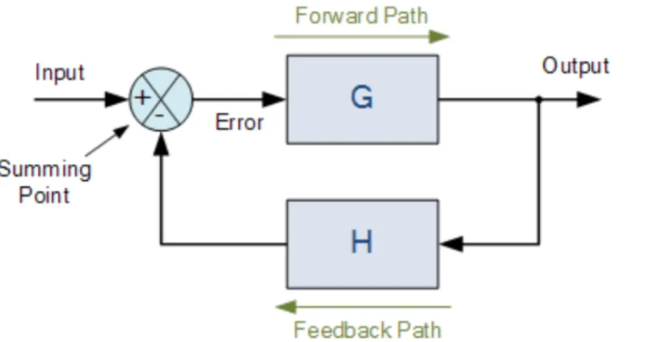
It is expected that most effort on this project will be put in fulfilling this design requirement. Closed-loop control is system is mostly used when we want to minimize the difference between input signal and the feedback signal (from the output). Figure9shows the block diagram for a simple closed loop system.
Figure 9: Block diagram of a closed-looped control system showing forward path and feedback path
In this project, the input signal is the desired force (by each finger) that we would like to exert on the object. The output is the actual force applied to the object, read by the force sensors at the contact points of each finger. This is fed back to negative terminal of the summing point. Thus, the system optimize the desired force by minimizing the error signal.
Since the desired force we want to exert on an object is dependent on the type of the object (for example, an egg may require less force than a light bulb). We will need a way of determining the amount of force that the user wants to exert on a particular object. For simplicity, this input from the user will stay constant throughout the process of grabbing. Future project may allow this input to be dynamic.
It should also be noted that the responsiveness of each finger sensor will also play a role in the feedback system, since the time it takes for a system to reach a desired error range is determined by the feedback response. Different sensors were explored for this purpose as discussed in section6.3.3.
5
Design Alternatives
Different aspects of designs described in section3, and different ways of achieving the design requirements in section4above, will be discussed in detail.
5.1
Structure
Various models of CAD design were discussed in section3.1and3.2. Table3discusses in details the benefits and drawbacks of each model. In this project, the InMoov Project’s hand design was chosen. Detailed reason for this choice can be found at section6.2.
CAD Design
Project
Benefits Drawbacks
Hand model by
Pizarroet al [6]
Technology required for such multi-material printing is available. Requires little assembly.
Design model is not readily available. May not allow threading of tension cables.
Design method
by Cal`ı’s research team [7].
Simple and intuitive model. Very life-like.
Requires time to learn the software. Allows only posing models. Hand actuations is man-ual.
Fabrication
method by De
Laurentis’ team [8]
Well-defined joints that require lit-tle assembly.
Model requires spring loaded joints. In-cludes unnecessary hardware components (hall-effect sensors). Designs not readily available.
Raphael’s hand de-sign [10]
Very flexible and functional. Can perform variety of gestures
Does not meet the life-like requirement. Does not meet the required force requirement.
Raptor Hand
and Flexy
Hand [11,12].
Simple assembly. Require little 3D printing.
Not suitable as active prosthetics. Does not allow independent finger movement.
Open Hand Project [13]
Very compact. Life-size. Low cost. Slow response time. Models not easy to as-semble. Does not support haptic sensing. InMoove project
design [14]
Life-size. Low cost. Independent finger movement. Support haptic sensing. Models easily available
Require extensive assembly.
Looqui’s
De-sign [15].
Life-size. Low cost. Independent finger movement. Support haptic sensing. Support finger crisscross-ing
Require extensive assembly. Models not eas-ily available.
Table 3: Structural design alternatives between the CAD models, describing the benefits and drawbacks of each model.
5.2
Electrical Components
Different ways of achieving the design requirements in section4above limit the electrical components that will be explored. Table4details the benefits and drawbacks of each component.
Component Benefits Drawbacks
DC motors Compact. Force feedback can be
done through current sensing.
Position control requires encoders. Addi-tional components are required in assembly. Current sensing is not easy. High-torque can easily burn out motors.
Servo motors Position control can be done with PWM. No additional components required in assembly. Geared, high-torque, and quick response.
Slightly larger in size than DC motors. Cur-rent sensing is tricky.
Flexy force sensor Small size. Very quick responsive. Broad range of sensing. Linear re-sponse.
Extremely pricy ($75 per part).
Small area force sensitive resis-tor [17]
Reasonable size. Quick response. Cheaper than Flexy sensor ($5 per part)
Lower range of sensing than Flexy sensor. Logarithmic response.
DIY foam
sen-sor [18]
Extremely cheap (< $1). Broad range of sensing.
Very slow response. Nonlinear response. As-sembly required.
Arduino
Uno/Nano
Mi-crocontroller [19]
Compact. Sufficient GPIOs that support PWM control and force sensing. Intuitive software inter-face.
Requires a separate hardware for crunching data from controller.
Raspberry Pi [20] Can run as a separate ROS plat-form. Powerful enough to crunch data from any controller.
Only one GPIO that support PWM (need ad-ditional hardware driver). Non-intuitive soft-ware interface
Table 4: Design alternatives between electrical components, describing the benefits and drawbacks of each component.
5.3
Software Design Decision
Different data types for encapsulating the state of each finger are explored. Options include making an array of finger objects containing position and sensor value of each finger, or single hand object containing two arrays, for finger position and sensor values. Since Python programming is used, PySerial and PyMata packages for serial communication with the microcontroller were considered.
6
Preliminary Proposed Design
6.1
Overview
Taking the variety of design alternatives detailed in Table3 and4into account, we proposed the follow-ing preliminary design for the robotic hand model, electrical components and software package choices. It should be mentioned that the design that we have chosen requires that the hardware components of the project be complete before testing the software component. Although this hinders the project’s hardware and software from proceeding in parallel, it is beneficial in the larger scope because it allows for multi-ple hardware and software upgrades even after the project has been commulti-pleted, making the project very modular.
6.2
Structure
For the structure of the hand, we found that it is most fitting to use the CAD model design from the InMoov Project.
Raptor hand and Flexy hand do not fit our requirement since they do not allow for independent finger control. Even though the CAD model designs presented by the Open Hand Project fit our use, since it uses DC motors, it makes the precise control of the hand position difficult without any encoders. Since the design for the Open Hand Project is so compact that it does not allow the addition of force sensors or encoders, it will not fulfill our design requirement. Looqui project’s design on the other hand contains extraneous functionalities, such as the ability to crisscross fingers, that we do not require. Moreover the designs for the models were not open source.
InMoov project, on the other hand, allows for independent finger movement by having each finger driven with individual tendon for contraction and extension. Moreover, since it makes use of servo motors and allows for sensor attachment, it provides ease of control of hand position as well as the force being exerted. Although, the fingers does not allow lateral movement, it allows to perform the required set of gestures. The only downside of this design is that the hand become quite heavy due to the use of multiple servos inside the forearm.
6.3
Electrical Components
6.3.1 Micro-Controllers
We have chosen to use Arduino Uno as our microcontroller. It allows for six PWM outputs, one for each five fingers and one for the wrist. It allows six analog inputs, just enough for five force sensors. Moreover, since Arduino is a widely used development platform, there are existing libraries available for communication with ROS, namely via the ROS serial library. This allows for ease of communication with other robotic components running ROS.
As mentioned above, an upgrade to Raspberry Pi can also be made if it can be fitted within the project timeframe. However, since the RaspberryPi only allows for only one PWM GPIO, an external PWM driver will have to purchased to multiplex between the servos. Since ROS can directly run on Raspbian (Debian variant of Linus for Raspberry Pi), there will be no need for libraries to enable communicate.
6.3.2 Motors
Since we chose to use the InMoov hand design, we will be making choices between servo motors. Five identical servos are needed for the fingers, and one for the wrist. Since we found out that each finger’s mo-tion range can be achieved with 90 degree servos, we chose HK15298 servos, which allows for a maximum torque of 15 kg-cm (208 oz-in) at 7.6V. Since we want our wrist to be able to rotate a full 180 degree, we chose MG646R which allows for a maximum torque of 12 kg-cm (166 oz-in) at 6V. In order for the tendons to be able to withstand the torque being exerted by the motors, they are also chosen to have a maximum of 22kg tensile strength. Different types of tendons were considered.The braided steel cable was chosen over fishing lines because it will not stretch when forced.
6.3.3 Sensors
From the three available choices of sensors explored, we decided that the small force resistive sensors from SparkFun [17] and the DIY sensors would be the ones tested (see Table4). The main reason behind eliminating the Flexy sensor is due to its price. Since cost is the one of the design requirements, using Flexy sensors would not fulfill the design requirement. The DIY sensor has been tested to give a maximum
resistance of 125kΩfor no force and the minimum resistance of 35kΩfor maximum force. Even though the size of these DIY sensors are small and can easily fit in our model, the response time of this sensors is really slow, making it not the ideal choice. Thus, we look for the other option of testing the small force resistive sensors from SparkFun. If we can attach theses sensors on the model without affecting its functionality, we will choose these sensors.
6.4
Software Choices
6.4.1 Closed-loop control simulation
To use appropriate gains for the closed-loop control system, we will need to simulate the system first. MATLAB’s simulink offers tools for simulating and calculating the required gains for PID control. After calculating the response time of the sensor of choice, we will simulate it in MATLAB and calculate the desired gains for the test objects (200 g standard cylindrical weight). Afterwards, several tests will be performed on other objects to see if variant in the values of gains are required.
6.4.2 ROS service and message passing
To accommodate ROS integration, we have decided to userosmsgtype to publish ”fingerPos” messages that contains an array of the position of each finger’s position in uint8 from 0 to 90 (for the fingers) and 0 to 180 (for the wrist). This will also be the data type of the messages converted from user commands that the hand will subscribe. We also aimed to implementrosservicesfor the force sensors, that will allow other nodes to knows that one of the sensors have hit the force threshold.
6.4.3 ROSserial
Since serial communication is easily supported by our microcontroller, we decided to useROSserialas our means of communication between the microcontroller and the computer running ROS. This is a package written in low-level C-code that creates a stand-alone ROS node for serial communication. This will allow publishing and subscribing ofrosmsgto and from the microcontroller and the computer.
6.4.4 ROS-MYO driver
Since we have decided to use the MYO controller to send control commands via ROS, we need a driver support for MYO. Fortunately, existing driver of ROS-MYO are made open source and available online. Since MYO controller has sensors not just for electromyographic signals, but also for gyroscopic signals, adaptations had to be made so that only the relevant messages are being translated into the commands.
7
Final Design and Implementation
7.1
Overview
Based on the design decisions made during the preliminary design stage, final design was improved upon using slight modifications. An Arduino Nano was chosen instead of an Arduino UNO. Short-tail force sensitive resistors from Pololu were used instead of the sensors from SparkFun or the DIY sensor. Braided fishing line was used instead of the braided steel cable. PyMata library was used for serial communication instead of ROSserial. Reasons behind these changes, and the final implementation steps are outlined.
7.2
Structure and Assembly
As stated in section6.2, the proposed 3D CAD model of the hand from the InMoov project was implemented with slight variations. The palm and fingers of the CAD model contains internal channels that allows for smooth threading of the tension cables. Since the dimensions of these channels are greatly affected when printed on the MakerBot Replicators, the palm and the fingers were printed using the Connex 500 Stratasys printer, which gives a high resolution. The forearm and wrist were printed using the MakerBot, since it can tolerate inaccuracies resulting from the print. Figure10shows that white color resulted from Stratasys print and the black color print from the MakerBot.
Another change from the proposed preliminary design is the tension cables. The braided steel cables were proposed as tension cables in the preliminary design since they do not stretch under tension. However, upon assembly, it was found out that steel cables require specialized tools to be able to thread in the fingers and pulleys, making it an extremely inconvenient choice. Braided fishing lines of similar strength, but smaller diameter was easily threaded. The trade off was the durability of the tension cables since the fishing line can easily tear upon repeated friction.
Pulleys that come with the original model is also changed. The reason is because there is a noticeable different in the length of travel by the tension cable between the extension and contraction of the finger. The contraction movement requires longer thread than extension, thus leaving the tension cable loose between movements. The solution to this problem is to use the pulley with two different diameters instead of a simple pulley (as seen in Figure10). The double-railed pulleys were 3D printed and tested to perform better than the single-rail pulley.
(a) 3D printed mold for the silicone finger tips, with finger tips in place
(b) 3D printed finger tip of the thumb, fitted with the a sili-cone finger tip, encasing the force sensor.
The final hardware adaptation, related to the choice of sensor, that was made is the addition of silicone finger tips. They serve the dual purpose of not only increasing the friction between the finger tips and object being grabbed, but also encasing the force sensors at the finger tip (as seen in Figure11b). The silicone finger tips were made using the 3D printed mold shown in Figure11a.
7.3
Electrical components
Few changes from the preliminary design were made to the electrical components. An Arduino Nano was used instead of an Arduino UNO due to size (they both share the same basic functionality). Upon testing it was found out that the servos for the fingers are also 180 degree servos, not 90 degree. This does not affect the design much. For aesthetic reasons, Pololu’s short-tail force sensitive resistors (FSRs) (shown in Figure
12) were used instead of the long-tail FSR from SparkFun (seen in Figure11b).
Figure 12: Short-tail FSR from Pololu citepololu-sensor
7.3.1 Schematics
Once all the necessary components of the system are gathered, each component is tested for functionality before prototyping the system. After all the preliminary testings are performed, a prototype of the system was constructed according to the schematics shown in Figure13. The FSRs are arranged as voltage dividers with a 100kΩresistor. The divided voltage from each sensor is attached to the ADC of the Arduino. The FSRs receive 5V supply regulated by the Arduino. Since the current running through each sensor is only ∼0.05mA (and the Arduino can source 200mA), protection circuit is not necessary. All the servos share a separate power source that can discharge 6A continuous current. The signal pins of the servos are attached to the six PWM pins available on the Arduino.
Figure 13: Schematics of the prototype of the robotic hand system sketched using Fritzing
7.3.2 Sensor Calibration
The sensors are calibrated using the standard mass 50 g. The mass is placed in the sensing area of the FSR that is laid flat. The following code was used the read out the sensor values with the weight of the mass applied to the sensor. The values are then stored and normalized.
for pin in SENSOR_PINS:
board.enable_analog_reporting(pin) while 1:
data = []
for pin in SENSOR_PINS:
data.append(board.analog_read(pin)) print data
7.3.3 Servo Calibration
Upon testing, it was discovered that the HK15298 servos do not respond to the full range of 0 to 180 degrees. Instead it was discovered that the sensors only respond to PWM values from 35 to 145. These values were used as the hard-coded internal limits for the fingers. To figure out the values, the following code was used to determine these values.
servo = input("Enter Servo: ") board.servo_config(servo) while 1:
pos = input("Enter a val: ") board.analog_write(servo,pos)
The user chooses the servo to be calibrated, and test the boundary values by incrementing and decre-menting the position. The result is an array of boundary values similar to the following:
LIMITS = [(34,120),(34,140),(35,150),(35,150),(35,140),(0,180)]
7.3.4 Porting to Perfboard
Once all the circuit is tested and calibrated on the protoboard, it is then ported to the perfboard for minia-turing. The schematics for the perfboards can be seen in Figure14aand14b. In Figure14a, each of the 3 pin headers from the servos compactly fits onto the shared power and ground bus. In Figure14b, the FSRs are spread into a voltage divider with the power and ground from the Arduino.
(a) Schematics of perfboard for 3-pin servos (b) Schematics of perfboard for FSR force sensors
7.4
Software design
Multiple changes were made in the final design of the software. The main change can be seen with the control algorithm. Even though the project aimed to implement a more sophisticated algorithm such as the PID, for the reasons that will be detailed in subsection7.4.4, a more coarse threshold detection algo-rithm was implemented. This implied that MATLAB simulations for the PID algoalgo-rithm did not need to be performed as planned in the preliminary design. Initially, the software for the hand was only designed to be a simple input/output communication with the micro-controller within a control loop, it was later decided that the hand should be implemented as a stand-alone finite state machine (as discussed in sub-section7.4.1). Serial communication between ROS and Arduino was determined to be carried out using the ROSserial package, that allows the Arduino to be a stand-alone ROS node. However, this implied that low-level software has to be written separate to the high-level ROS control code.
7.4.1 Finite State Machine
Figure15shows the designed finite state machine with “Open” as the resting state. From “Open”, if the hand receives a “mimicEvent”, it will go into a mimic state, and mimic hand gestures performed through a controller (MYO or LeapMotion or KeyBoard) by the human hand.
If the hand receives a “gestEvent”, it will go into a “Gesturing” state, where it will wait for a particular gesture to be performed. Gestures are a sequence of hard-coded values of servo positions stored by the ges-ture library. Once the gesges-ture is performed, a “reached” event is triggered, bring the hand into a “Gesges-ture” state, where it will then accept the next gesture upon the next “gestEvent”.
Similarly, if the hand receives a “grabEvent”, the hand will go into a “Grabbing” state, where it will use the sensors on the finger tip and grab an object according to the control algorithm (described in subsection
7.4.4) without crushing it. A “reached” event is triggered once the the servos are at the max limit (set by the servo calibration discussed in subsection7.3.3) or once the sensor of the finger has detected an object. Despite their similarities, the main difference between “Gesturing” and “Grabbed” is that, once the hand is in the “Grabbed” state, it can only either receive a “closeEvent” forcing the hand to crush the object it was grabbing by going to the “Close” state, or a “clear” event that will take the hand back into the resting “Open” state.
Any state, except “Gesturing” and “Grabbed” (both of which are blocking states), will return to the resting state “Open” upon receiving a “clear” event.
This is all implemented in ROS by writing a python script that encapsulates the entire hand as an FSM-Hand object. The script, along with the entire project can be found onGitHub.
7.4.2 ROS implementation
Once the design of the state machine is established, implementing the state machine in ROS becomes intu-itive since ROS nodes can encapsulate the states. Figure16shows the nodes and their respective messages that are being published or subscribed. The “Hand Controller” node implements the finite state machine, keeping track of the internal state of the hand using the FSMHand object, and communicates directly with the Arduino via serial communication (details described in subsection7.4.3). If the hand is in “Mimic” state, it will subscribe to “Finger msg” topic from translator nodes, such as “Keyboard teleop”,“Leap teleop” or
Figure 16: Node diagram of the finite state machine implemented in ROS, showing how nodes communi-cate with via message passings
“MYO teleop”. If the hand is in “Gesture” state, it will subscribe to “Finger msg” topic from the gesture library node, named “Gesture teleop”. All the events/transitions that trigger the state machine are fed to the “Hand Controller” node by the “StateControl” node through “Event msg” topic. The “Hand Con-troller” node also publishes “Sensor msg” topic for users who would like to have it echoed/subscribed for additional functionality. All the topics are custom made messages implemented in ROS. “Finger msg” and “Sensor msg” topics are both of typeuint16[]and the “Event msg” topic is of typestring. The message creating and node implementations, along with the entire project can be found onGitHub.
7.4.3 Serial Communication
Our choice of package used for serial communication evolved gradually from the preliminary design. Our initial design idea was to use ROSserial package, implemented as low-level C-code for the micro-controller, that allows the Arduino to serve as a stand-alone node. This disagrees the exiting software architecture since the “Hand Controller” will no longer encapsulate the Arduino hardware. Moreover, upon discovering the intricacies involved in specialized message passing procedures of ROSserial, another package PySerial that communicates with serial devices directly through Python was considered.
Even though PySerial allows direct communication with Arduino, the code for parsing of the serial messages still has to be done in low-level C-code. This becomes a problem when a stream of serial data needed to be processed. Since the hand needs to meet the requirement set by response time (see section
4.4), specialized parsing code is needed. The final option for serial communication that was discovered is using a protocol called “Firmata”.
Firmata is a protocol that allows direct access to the hardware of the micro-controller via serial com-munication. Figure17describes the differences in using the Firmata and running a parsing script on the Arduino. Traditionally, an Arduino communicating via serial would have a parsing script that is looping. Depending on the script and the message received, the Arduino responds via GPIOs. However, using Fir-mata, the serial messages that are transmitted from the computer are actually the script that can directly affect the Arduino’s GPIOs; thus abstracting out the low-level C-code, and giving full access of the Arduino to the computer. PyMata library, Python library for Firmata protocol, was used.
7.4.4 Control Algorithm
Even though a control algorithm with negative feedback was proposed to be implemented, upon testing of the force sensors, it was found out that the resistance to force curve is logarithmic (as shown in figure
18). This implies that slight changes in position of the servo can result in drastic changes in sensor value; making it hard to implement stable a negative feedback system.
Figure 18: Resistance vs. Force curve of the short-tail FSRs from Pololu [21], showing logarithmic relation
However, since the sensors are already implemented, feedback from them is still possible. In order to overcome the instable response of the sensor outputs for each the servo position input, a more coarse control algorithm that detects sensor threshold was implemented. The snippet of the code for this threshold detection can be seen below.
while curState == ’grabbing’: if reached:
target = input("Please enter target position: ")
threshold = input("Enter the target force threshold: ") data = board.analog_read(pin)
print "Sensor: ", data, "Cur_pose: ", cur_pos
if cur_pos != target and max(data) < threshold: reached = False
step = 1 if cur_pos < target else -1 cur_pos += step board.analog_write(pin, cur_pos) else: reached = True time.sleep(0.1) 7.4.5 Mimic
The mimicking functionality of the hand is achieved by establishing a message passing between one of the translator nodes, such as Keyboard teleop, Leap teleop or MYO teleop, and the “Hand controller” node. (as shown in Figure16). In this project, we have implemented two of the translator nodes, Keyboard teleop and MYO teleop in ROS running inside a virtual machine. Teleoperation over Leap teleop is demonstrated on the host computer since the software development package (SDK) for the LeapMotion controller does not run in virtual box.
For “Keyboard teleop” node, the node publishes messages of “Finger msg” topic that is subscribed by the “Hand Controller”. Each keystroke is assigned a position value using a dictionary data type. A KeyTelop object keeping track of the last command and the dictionary is constructed. Below is a snippet of the code:
class KeyTeleop(object):
fng_bindings = {’q’: 0, ’w’: 10, ’e’:20, ’r’:30, ’t’:40, ’y’:50, ’u’:60, ’a’: 70, ’s’: 80, ’d’:90, ’f’:100, ’g’:110, ’h’:120, ’j’:130, ’z’: 140, ’x’: 150, ’c’:160, ’v’:170, ’b’:180}
fng_speed = {’n’:2, ’m’:-2}
def run(self):
while not rospy.is_shutdown(): ch = self.get_key()
self.process_key(ch) self.update()
Similar to the “Keyboard teleop” node, “MYO teleop” node also publishes messages of “Finger msg” topic that is subscribed by the “Hand Controller”. In addition, “MYO teleop” node also subscribes to the “MYO emg” topic, which is published by the MYO driver upon launching. Several different types of sen-sor data can be obtained from the MYO driver, and future work is suggested to improve better functionality (see section13). Currently, we are only obtaining the raw EMG (electromyographic) signals, and perform-ing a very coarse signal processperform-ing to determine whether the hand beperform-ing mimicked is Open or Closed. Depending on the processed signal, “MYO teleop” node publishes the relevant finger position data. Below is a snippet of the code:
OPEN = 150; CLOSE = 35; THRESHOLD = 400 def callback(emg):
pub = rospy.Publisher(’finger_pose’, Finger, queue_size=10) command = OPEN if all_high(emg.data, THRESHOLD) else CLOSE pub.publish(command)
Since the SDK for the LeapMotion driver requires computationally intensive calculations, it does not run well inside a virtual machine. Thus, to demonstrate the capability of LeapMotion, we had to abstract out ROS from the picture and use PyMata directly inside a python script to control the servos inside the 3D printed hand. The LeapMotion API grants the developer with access to processed data from the sensors inside LeapMotion. It gives out x, y, z positions of each joint and vectors of each bone segment. Details on the API of Leap Motion Python SDK can be foundhere.
In our demonstration, we will map the y position of the distal joint (the last joint at the finger tip) with the the corresponding finger’s servo position. Lower y position values correspond to curling and higher y position values correspond to extension. Since the Leap Motion processes the data frame by frame at 50 fps, we can send the processed data directly to the Arduino inside the loop via PyMata. Below is the snippet of the code:
METACARPAL = 0; PROXIMAL = 1; INTERMEDIATE = 2; DISTAL = 3 for servo in SERVO_PINS:
board.servo_config(servo)
def on_frame(self, controller): frame = controller.frame() for hand in frame.hands:
for servo, finger in zip(SERVO_PINS, hand.fingers): distal_bone = finger.bone(DISTAL)
x,y,z = distal_bone.next_joint
8
Performance Estimates and Results
8.1
Size
Our choice of 3D design allows the hand to be within the required size limit of approximately 50cm in length and 10cm diameter cylinder as the forearm.
8.2
Gripping
Based on the maximum limit of desired weight that we would like to grip (as defined in subsection4.2), we performed a test by gripping a standard cylindrical weight of 200 g. However, due to the shape of the available cylindrical weight, the hand could not perform an efficient grip. So another test cylinder was chosen. Figure19shows the hand gripping a cylindrical can of WD40 that is also approximately 200 g.
Figure 19: The 3D printed hand performing a gripping action showing its capability to meet the weight limit criterion
8.3
Gestures
Based on the gestures defined by our design requirements in subsection4.3, we have built a node that serves as a gesture library containing five basic human-understandable hand gestures. One can publish gesture topic, of typestringwhile the hand is in “Gesture” or “Open” state (as discussed in subsection
7.4.2). Figure20shows the 3D printed hand performing the five gestures.
(a) Saying ‘hi’ using vertical open hand
(b) Signaling ‘okay’ using index and thumb
(c) Signing a ‘peace’ signal using in-dex and middle finger
(d) Pointing gesture using the index finger (e) Signaling approval by giving a thumbs up
Figure 20: Figures of five human understandable gestures performed by the 3D printed hand while in “Gesture” state
8.4
Response Time
The response time of the hand to the control signals is not only determined by the rate of Serial communi-cation, but also by the built-in control system inside the servo that translates the pulse-width of the PWM signal to the position of the servo. The response time of the servo is empirically tested using the keyboard teleoperating script that test runs the servo from 0 to 180. The test video islinked. As stated in subsection
7.4.3, serial communication was finally decided to be implemented using Firmata protocol at the baude rate of 9600. However, messages are being passed at 50Hz to allow for elbow-room in processing time. This results in a smooth mimicking functionality as seen in thedemo videoof mimic with Leap Motion controller.
8.5
Closed Loop Force Control
Using the coarse feedback algorithm for threshold detection (discussed in subsection7.4.4), we perform a test of crushing a plastic cup. First a force threshold value equivalent to the weight of a 30 g object is applied. From figure18, we calculated that this corresponds to the ADC read of 680 (10 bit) given a 5V reference. Figure 21a shows the plastic cup slightly dented by the force. Then, a force threshold value equivalent to the weight of a 70 g object is applied. This corresponds to the ADC read of 800 (10 bit). Figure
21bshows the plastic cup even more dented by the greater force.
(a) Plastic cup dented by a force equivalent to the weight of 30 g mass applied by the index finger
(b) Plastic cup dented further by a force equivalent to the weight of 70 g mass applied by the index finger
Figure 21: Testing closed loop force control via threshold detection using sensor feedback form the index finger
![Figure 1: Shadow robotic hand showing its dexterity with fragile light bulb [4].](https://thumb-us.123doks.com/thumbv2/123dok_us/10117530.2912304/12.918.401.517.192.404/figure-shadow-robotic-hand-showing-dexterity-fragile-light.webp)
![Figure 3 shows threaded finger with tension cables from Borghesan’s team [5]. Their team used five tension cables to achieve most life-like actuation](https://thumb-us.123doks.com/thumbv2/123dok_us/10117530.2912304/14.918.271.647.530.868/figure-threaded-finger-tension-borghesan-tension-achieve-actuation.webp)
![Figure 4: Hand design of Pizarro’s team, showing its skin (black) and exposed bone (white) structure [6].](https://thumb-us.123doks.com/thumbv2/123dok_us/10117530.2912304/16.918.156.760.711.872/figure-hand-design-pizarro-showing-black-exposed-structure.webp)
![Figure 5: Static to articulated hand model using Cal`ı’s transformation metho [7].](https://thumb-us.123doks.com/thumbv2/123dok_us/10117530.2912304/17.918.130.788.368.570/figure-static-articulated-hand-model-using-transformation-metho.webp)