Fire Control/Communicator
Content
Section 1
Introduction
... 1-1 1.1 How to Use This Manual ... 1-1 1.2 Optional Accessories ... 1-2Section 2
Specifications and System Planning
... 2-1 2.1 Electrical Specifications ... 2-1 2.2 Environmental Specifications ... 2-1 2.3 Wiring Specifications ... 2-2Section 3
Agency Listings, Approvals, and Requirements
... 3-1 3.1 Federal Communications Commission (FCC) ... 3-1 3.1.1 FCC Warning ... 3-1 3.2 Underwriters Laboratories (UL) ... 3-2 3.2.1 Requirements for All Installations ... 3-2 3.2.2 Requirements for Central Station Fire Alarm Systems ... 3-2 3.2.3 Requirements for Local Protected Fire Alarm Systems ... 3-3 3.2.4 Requirements for Auxiliary Protected Fire Alarm Systems for Fire Alarm Service ... 3-3 3.2.5 Requirements for Remote Station Protected Fire Alarm Systems - Polarity Reversal ... 3-3 3.3 California Fire Marshal (CFM) ... 3-4 3.4 Factory Mutual (FM) ... 3-4 3.5 Materials & Equipment Board of Acceptance (MEA) ... 3-4Section 4
Installation Overview
... 4-1 4.1 Model 5204 Wiring Diagram ... 4-1 4.2 Current Draw Worksheet ... 4-2 4.2.1 Worksheet Example ... 4-3 4.2.2 Worksheet Requirements ... 4-4Section 5
Control Panel Installation
... 5-1 5.1 Grounding the Model 5204 Cover ... 5-25.5 Mounting the 5204 ... 5-3 5.6 Terminal Strip Description ... 5-3 5.7 Model 5205 Dialer and Telephone Line Connection (Optional) ... 5-5 Installation ... 5-5 Ring Detect Circuit ... 5-6 5.8 Cable Connectors ... 5-7 Status (P1) ... 5-7 Model 5230 (P2) ... 5-7 Power Supply (AC) Connector (P4) ... 5-7
Section 6
Compatible Product Installation
... 6-1 6.1 Zone Wiring ... 6-1 6.1.1 Four-Wire Smoke Detector Connection ... 6-2 6.1.2 Two-Wire Smoke Detector Connection ... 6-3 Notes for Both Tables ... 6-3 6.2 Connections to Compatible Silent Knight Products ... 6-6 6.2.1 Model 4180 Status Display Module ... 6-6 6.2.2 Model 5220 Direct Connect Module ... 6-7 6.2.2.1 Installation ... 6-8 6.2.2.2 City Box Connect (24 VDC Systems Only) ... 6-8 6.2.2.3 NFPA 72 Polarity Reversal (12 or 24 VDC Systems) ... 6-9 6.2.3 Model 5230 Remote Annunciator ... 6-9 6.2.3.1 Setting ID Codes ... 6-9 6.2.3.2 Wiring the 5230 Remote Annunciator ... 6-10 6.2.3.3 Mounting the 5230 Remote Annunciator ... 6-11 6.2.4 Model 5395 Distibuted Power Module ... 6-11 6.2.5 Model 7181 Zone Converter ... 6-12 6.3 Supervised Notification Device Outputs ... 6-13 6.4 Auxiliary Relays ... 6-20 6.5 External Silence Keyswitch (Optional) ... 6-21Section 7
Normal Operation
... 7-1 7.1 Built-in Touchpad and Model 5230 Annunciator Operation ... 7-2 7.1.1 Operating Modes ... 7-5 7.1.2 Built-in Touchpad Display Codes ... 7-5 7.1.3 Silencing the System ... 7-7 7.1.4 LED Indicators ... 7-7 7.2 System Testing ... 7-8 7.2.1 Fire Drills (Mode 20) ... 7-8 7.2.2 Walk Test (Mode 22) ... 7-8 7.2.3 Automatic Self Test ... 7-8 7.2.4 Watchdog Circuit ... 7-8 7.3 Zone Characteristics ... 7-9 7.3.1 Zone Type ... 7-9Content
Section 8
Programming
... 8-1 8.1 EEPROM Information ... 8-1 8.2 Downloading ... 8-2 8.3 How to Use Step Programming ... 8-2 8.3.1 Entering Step Programming (Mode 27) ... 8-3 8.3.2 Programming Options ... 8-3 8.3.3 Advancing to the Next Option ... 8-4 8.3.4 Going to a Specific Step ... 8-4 8.3.5 Viewing Previously Programmed Data ... 8-5 8.3.6 Correcting Errors ... 8-5 8.3.7 Entering Hexadecimal Digits ... 8-5 8.3.8 Programming Examples ... 8-6 Example 1: Choosing a Programming Option from a Menu ... 8-6 Example 2: Programming Location Description Names ... 8-6 8.3.9 Exiting Step Programming ... 8-7 8.4 Step Programming Options ... 8-8 8.4.1 Programming Steps ... 8-8Section 9
Troubleshooting
... 9-1 9.1 Silencing Notification Devices ... 9-1 9.2 Earth Ground Fault Troubleshooting ... 9-1 9.2.1 P3 and P4 Fault ... 9-1 9.2.2 Accu-Zone‚ Troubleshooting (Mode 25) ... 9-2 Special Notes ... 9-3 9.3 Troubleshooting and System Messages ... 9-4Section 10
Central Station Reporting
... 10-1 10.1 Power Loss Reporting ... 10-1 10.2 Reporting Formats ... 10-1 10.2.1 SIA Format Printed Messages ... 10-2 10.2.2 Silent Knight 3/1 and Sescoa 3/1 Formats ... 10-3 10.2.3 Silent Knight FSK and 4+2 Formats ... 10-4 10.2.4 Radionics BFSK Format ... 10-5Appendix A
Section 1
Introduction
The Model 5204 is a low-cost fire alarm control panel with optional communicator that meets UL 864 and NFPA 72 requirements. It is available with a 12 or 24 VDC power supply, which you can select in the field. The 5204 cabinet can be surface mounted or flush mounted.
1.1
How to Use This Manual
The Model 5204 Fire Control/Communicator Installation Manual (P/N 150644) is intended for those people involved with the installation, maintenance, and programming of the 5204 panel. It covers wiring, connection to compatible products, normal operation, programming, troubleshooting, and central station reporting.
This manual is a comprehensive guide. It provides detailed instructions and can be used for reference. The installation manual is organized chronologically by the tasks that need to be performed to get the panel operating according to your needs. You can skip sections that do not apply to your installation.
In this manual, the following conventions are used:
ENTER or
Represents a key that you press on a touchpad.
Shaded displays represent messages that you see on the built-in touchpad (7-segment) light emitting diode (LED) display.
SMOKE RESET TIME Words typed in this font represent messages that you see on a liquid
crystal display (LCD).
1.2
Optional Accessories
The following Silent Knight components can be used with the Model 5204 panel.
Table A-1: Compatible Components (Manufactured by Silent Knight)
Model What it Does
2608 Ground Start Relay Used for ground start phone lines(not UL listed).
4180 Status Display Module For remote annunciation of alarm and trouble status information for each zone.
5220 Direct Connect Module For direct alarming and trouble transmission from the 5204 to a supervising station.
5230 Remote Annunciator Provides complete system control. Includes touchpad (keypad) with membrane keyswitches, back-lit LCD indication of zone and system status, and built-in speaker for audible annunciation. Used for programming with English-language prompts.
Quick connect program cable, part number 130294
For temporarily connecting the 5230 to the 5204 for programming.
5293 Distributed Power Module
For connecting more notification devices than the 5204 normally allows.
5541 Downloading Software For remote programming of the 5204.
5530 Modem Modem for downloading; required if using the 5541 software. 5205 Dialer Module Enables the 5204 to function as a communicator panel.
7181 Zone Converter Converts a zone from class B (style B) to class A (style D) or from class A to class B. One 7181 per zone to be converted.
Section 2
Specifications and System Planning
2.1
Electrical Specifications
2.2
Environmental Specifications
It is important to protect the 5204 control panel from water. To prevent water damage, the following conditions should be AVOIDED when mounting the units:
• Do not mount directly on exterior walls, especially masonry walls (condensation) • Do not mount directly on exterior walls below grade (condensation)
• Protect from plumbing leaks
• Protect from splash caused by sprinkler system inspection ports
• Do not mount in areas with humidity-generating equipment (such as dryers, production machinery)
When selecting a location to mount the 5204 control panel, the unit should be mounted where it will NOT be exposed to temperatures outside the range of 0° C-49° C (32° F-120° F) or humidity outside the range of 10%-85% at 30° C (86° F) noncondensing.
Circuit 12-Volt Panel 24-Volt Panel
Primary AC 120 Vrms at 60 Hz, 2500 mA rms 120 Vrms at 60 Hz, 2500 mA rms
Total External DC Load 3.0A 3.0A
Accessory Power 9.5 V to 13.8 V max., 1500 mA 19.7 V to 27.6 V max., 1500 mA
+12 V Accessory Power 8.0 V to 14.0 V, 175 mA 11.5 V to 14.0 V, 175 mA
Bell Power 9.3 V to 13.8 V max., 1500 mA 19.8 V to 27.6 V max., 1500 mA
Smoke Power 9.3 V to 13.8V max., 1000 mA 19.7 V. to 27.6 V. max., 1000 mA
Battery Charging Voltage 13.5 to 13.8 V 27.0 V - 27.6 V
Minimum Low Battery Detect 10.2 V 20.4 V
Minimum Low AC Detect 100 Vrms at 60 Hz, full load 100 Vrms at 60 Hz, full load
Minimum Class B Trouble Detect 1.5 mA 2.4 mA
Maximum Class B Alarm Detect 11.7 mA 12.1 mA
Maximum Watchdog Response Time 50 sec. 50 sec.
2.3
Wiring Specifications
To avoid induced noise (transfer of electrical energy from one wire to another), keep input wiring isolated from high current output and power wiring. Induced noise can interfere with telephone communication or even cause false alarms. Avoid pulling one multiconductor cable for the entire panel. Instead, separate the wiring as follows:
DO NOT pull wires from different groups through the same conduit. If you must run them together, do so for as short a distance as possible or use shielded cable. Connect the shield to circuit ground at the panel. You must route high and low voltages separately.
For the same reasons, you should route the wiring within the cabinet around the perimeter of the cabinet. It should not cross the printed circuit board where it could induce noise into the sensitive microelectronics or pick up unwanted RF noise from the high speed circuits.
High frequency noise, such as that produced by the inductive reactance of a speaker or bell, can also be reduced by running the wire through ferrite shield beads or by wrapping it around a ferrite toroid. See Figure 2-1.
Figure 2-1 Wiring Identification
High current input/output: AC power, speaker, and notification device wiring
Low current input/output: Annunciator and zone loop wiring
Section 3
Agency Listings, Approvals, and Requirements
3.1
Federal Communications Commission (FCC)
1. If requested by the telephone company, the following information must be provided before the 5204 can be connected to the phone lines:
2. This device may not be directly connected to coin telephone or party line services.
3. This device cannot be adjusted or repaired in the field. In case of trouble with the device, notify the installing company or return to:
Silent Knight Security Systems 7550 Meridian Circle
Maple Grove, MN 55369-4927 612-493-6455
800-328-0103
4. If the 5204 or 5205 dialer causes harm to the telephone network, the telephone company will notify the user in advance that temporary discontinuance of service may be required. If advance notice is not practical, the telephone company will notify the user as soon as possible. Users have the right to file complaints, if necessary, with the Federal Communi-cations Commission.
5. The telephone company may make changes in its facilities, equipment, operations, or pro-cedures that could affect the operation of the equipment. If this happens, the telephone company will provide advance notice to allow you to make the necessary modifications to maintain uninterrupted service.
3.1.1
FCC Warning
A Manufacturer: Silent Knight Security Systems B Model Number: 5204
C FCC registration number AC6USA-73710-AL-E Ringer equivalence: 0.9B
D Type of jack (to be installed by the telephone company
RJ31X
3.2
Underwriters Laboratories (UL)
The 5204 is UL listed as a control unit for use in NFPA 72 systems. If the 5204 and its accessories are to be used as part of a UL installation, carefully read the UL requirements in this section. For more information on the following NFPA 72 standards, refer to the NFPA National Fire Alarm Code, 1993 Edition.
• Chapter 3
Local Protected Fire Alarm Systems • Chapter 4
Central Station Fire Alarm Systems
Auxiliary Protected Fire Alarm Systems for Fire Alarm Service (City Box) Remote Station Protected Fire Alarm Systems (Polarity Reversal)
3.2.1
Requirements for All Installations
General requirements are described below. When installing an individual device, refer to the specific section of the manual for additional requirements. See also the subsection below that describes special requirements for the type of installation (for example, Central Station Fire Alarm systems, Local Protected Fire Alarm systems, and so on).
1. All AC wiring to and from the 5204 cabinet must be enclosed in conduit.
2. Total 24-hour standby current must not exceed 875 mA in 12V mode or 438 mA in 24V mode. Total 60-hour standby current must not exceed 350 mA in 12V mode or 175 mA in 24V mode.
3. All electrical connections must comply with the ratings shown in Section 5.6.
4. Because the 5204 panel itself is the main source of alarm and trouble annunciation, you must select a location for the panel that allows alarms and troubles, including pre-alarms, to be heard by end-users responsible for maintaining the panel.
3.2.2
Requirements for Central Station Fire Alarm
Systems
1. You must program a phone number and a test time (See Section 8, Step 69 and Step 76) so that the 5204 sends an automatic daily test to the central station.
2. In systems using class A (style D) zones (converted using the Model 7181 Zone Con-verter), do not use more than 5 waterflow devices. (See Section 6.2.5.)
Agency Listings, Approvals, and Requirements
3.2.3
Requirements for Local Protected Fire Alarm
Systems
At least one UL listed supervised audible appliance must be used.
3.2.4
Requirements for Auxiliary Protected Fire Alarm
Systems for Fire Alarm Service
1. Do not exceed the current load restrictions shown in Section 4.
2. The Model 5220 Direct Connect module must be installed (see Section 6.2.2 for wiring).
3.2.5
Requirements for Remote Station Protected Fire
Alarm Systems - Polarity Reversal
1. Do not exceed the current load restrictions shown in Section 4.
3.3
California Fire Marshal (CFM)
The CFM approval number for the 5204 is 7165-0559:117
3.4
Factory Mutual (FM)
The 5204 is FM approved under project # OW6A3.AY when used in conjunction with the Silent Knight Model 9000 Receiver.
3.5
Materials & Equipment Board of Acceptance
(MEA)
The 5204 is now approved under MEA. Previously, approval was given from the City of New York Board of Standards and Appeals (BSA). The 5204 is now approved under MEA Number 429-92-E.
Section 4
Installation Overview
4.1
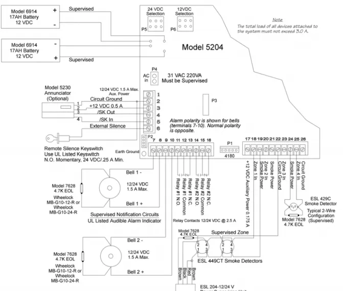
Model 5204 Wiring Diagram
Figure 4-1 is a wiring diagram for wiring the various components of the Model 5204 panel. Any device connected to terminal 24 must be UL listed for fire use, and must be rated at 12 V/24 V. Terminals 22 and 26 are the only terminals that should be used to return smoke power and should not be used for any other purpose.
4.2
Current Draw Worksheet
Device Number of
Devices Current per Device
Standby
Current Alarm Current
For each device, use this formula:This column X This column = Current per number of devices 5204 Fire Control/
Communicator 1
Standby: 120 mA mA
Alarm: 400 mA mA
4180 Status Display module (2 max.) Standby: 20 mA mA
Alarm: 140 mA mA
5205 Dialer 1 Standby : 10 mA mA
Alarm: 100 mA mA
5220 Direct Connect module 1 Standby: 50 mA mA
Alarm: 50 mA mA
5230 Remote Annunciator (3 max.) Standby: 60 mA mA
Alarm: 120 mA mA
7181 Zone Converter (4 max.) Standby 12V/24V: 52/35 mA mA
Alarm 12V/24V: 90/65 mA mA
A Current Subtotals: mA mA
Smoke Detectors Refer to device manual for current ratings. See Tables 6-2 and 6-3 for max. # per loop.
Standby: mA mA Alarm: mA mA Standby: mA mA Alarm: mA mA Standby: mA mA Alarm: mA mA B Current Subtotals: mA mA
Notification Devices Refer to device manual for number of devices and current ratings.
Alarm: mA mA Alarm: mA mA C Current Subtotals: mA mA Additional Devices Standby: mA mA Alarm: mA mA Standby: mA mA Alarm: mA mA Standby: mA mA Alarm: mA mA Standby: mA mA Alarm: mA mA
Installation Overview
4.2.1
Worksheet Example
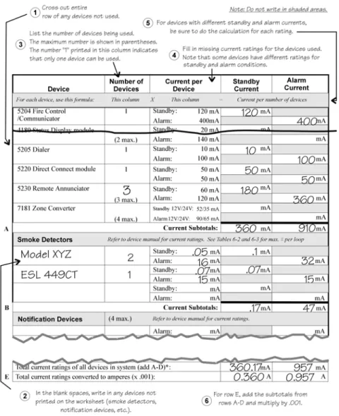
A worksheet is included to help you calculate the amount of current the system draws on standby (idle) and in active (trouble or alarm) conditions. Refer to Table 4-2 to see the different battery sizes available and the maximum standby current load each can support. Figure 4-2 illustrates how to complete the worksheet:
Figure 4-2 Current Draw Worksheet Example
Maximum current draw for signaling devices - 1.5 A
(See Section 6.3 for additional information on signaling outputs.) Maximum Loop resistance for smoke detectors - 30 ohms
To measure maximum loop resistance, connect an ohmmeter across the leads of a discon-nected loop.
4.2.2
Worksheet Requirements
The following steps must be taken when determining 5204 current ratings:
1. For the Model 5204, you must measure the alarm (active) current. If only one current rat-ing is listed, the draw for that device is the same whether the system is in alarm or standby condition. The exception is for notification devices, which are rated at alarm current only. Standby current for sounding devices is 0 mA.
2. To measure the maximum alarm current of the panel, measure the current draw (with no devices connected to the panel) by connecting a DC amp meter in series with one of the batteries. Disconnect the AC power source. Put the panel in alarm. The meter will indi-cate the alarm current, which will be in the range of 120-400 mA. Fill in the system alarm current in the Current per Device column on the Current Draw worksheet. You can esti-mate without measuring the alarm current by filling in the maximum total alarm current of 400 mA.
Note: In a 12-volt system, measure the current from both batteries (disconnect both grounds).
3. For smoke detectors, notification devices and devices not mentioned in the manual, refer to the device manual for the current ratings. The worksheet example shown on the previ-ous page provides rough estimates for a “worst case” installation.
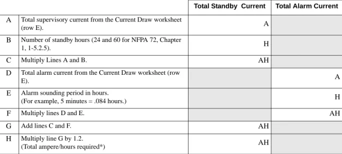
4. Use Table 4-1 to determine the battery amp hour rating needed for your installation. Refer to the example (Figure 4-3) that follows. Note that the calculated rating in Row H cannot exceed the ratings shown in Table 4-2).
* Use next size battery with capacity greater than required.
Table 4-1: Battery Calculations
Total Standby Current Total Alarm Current
A Total supervisory current from the Current Draw worksheet
(row E). A
B Number of standby hours (24 and 60 for NFPA 72, Chapter
1, 1-5.2.5). H
C Multiply Lines A and B. AH
D Total alarm current from the Current Draw worksheet (row
E). A
E Alarm sounding period in hours.
(For example, 5 minutes = .084 hours.) H
F Multiply lines D and E. AH
G Add lines C and F. AH
H Multiply line G by 1.2.
Installation Overview
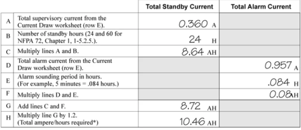
Figure 4-3 Battery Calculation Example
5. Refer to Table 4-2 to verify the battery size you need to provide at least the total standby current you have calculated. If the installation must meet requirements for NFPA 72 (Auxiliary Protected Fire Alarm Systems for Fire Alarm Service or Remote Station Pro-tected Fire Alarm Systems - Polarity Reversal), the total standby current cannot exceed the amount shown in the last column of the following table:
* Required for NFPA 72 Auxiliary Protected Fire Alarm systems for Fire Alarm Service (City Box) and Remote Station Protected Fire Alarm systems (Polarity Reversal).
Warning!
Silent Knight does not support the use of batteries smaller than those listed in Table 4-2. If you use a battery too small for your installation, the system can overload it and you may have less than the required 24 hours standby power. Use Table 4-1 to calculate the correct battery amperes/hour rating needed for your installation.
Table 4-2: Maximum Battery Standby Load
Rechargeable Battery Size
Max. Load for 24 hrs. Standby, 5 mins. Alarm
*Max. Load for 60 hrs. Standby, 5 mins. Alarm
17 Amp Hours 438 mA 175 mA
The following formula was used to calculate the figures in Table 4-2: I = [AH ÷ H] x 0.70
6. Ensure that the total alarm current you calculated, including current for the panel itself, does not exceed 3.5 A. This is the maximum alarm current allowable, whether the panel provides 12 V or 24 V of smoke power.
Where: I = Standby current
AH = Ampere-hour rating of battery
H = Standby hours
Section 5
Control Panel Installation
The major components of the Model 5204 PC board are described in this section. Figure 5-1 shows the 5204 (fuseless) printed circuit board.
5.1
Grounding the Model 5204 Cover
Before connecting power to the 5204, connect the earth ground wire to the base and cover. Make sure that the ring lugs are oriented properly. The proper connection and orientation are shown in Figure 5-2. The star washers must be located between the ring lugs and the painted surfaces.
After attaching the cover and base, make a slight bend in the wire attached to the cover. This is to keep it from being caught between the cover and base when the cover is closed.
Figure 5-2 Connecting the Ground Wire
5.2
Smoke Power Selection
With AC power removed and batteries removed, insert the supplied jumper block (P/N 130412) into P5 for 24V or P6 for 12V.
5.3
Power Supply Wiring
A transformer is used to supply 31 VAC (220 VA) to power the system under normal
conditions and to supply charging current to the backup batteries. The primary winding must
Caution
To avoid the risk of electrical shock, Do NOT apply power to the Model 5204 until told to do so in this manual (See Note in Section 6.2).
Control Panel Installation
5.4
Battery Connection
Note: When using two batteries, it is recommended that they be of the same ampere hour (AH) rating and approx-imately the same age.
Battery cable connectors enable installation of one or two 12 VDC, 17 A rechargeable batteries. Two sets of battery leads are provided for battery connection. When connecting a single battery, connect one of the red leads to the positive side of the battery. Connect a black lead to the negative side of the battery.
If using a second battery, connect the remaining lead to the positive side of the second battery. Connect the remaining black lead to the negative side of the second battery.
5.5
Mounting the 5204
Read the environmental specifications in Section 2.2 before mounting the 5204 panel. The panel should be accessible to “Main Drop” wiring runs. The 5204 panel should be mounted as close to the center of the building as possible and located within a secured area, but should be accessible for testing and service. End-users responsible for maintaining the panel should be able to hear alarms and troubles. When selecting a location, keep in mind that the panel itself is the main source of alarm and trouble annunciation.
Mount the 5204 so it is firmly secured to the wall surface. When mounting the 5204 on concrete, especially when moisture is expected, attach a piece of 3/4-inch plywood to the concrete surface and then attach the 5204 to the plywood. Also mount any other desired components (such as external printer) to the plywood. If you will be flush mounting the cabinet, the hole for the enclosure should be 14 1/2” x 19 1/8” (width x length of box only). Do NOT flush-mount in a wall designated as a fire break.
5.6
Terminal Strip Description
The terminal strips on the PC board are nonremovable. Table 5-1 below lists the function and electrical rating of each terminal. Note the following:
• The total load of all devices attached to the system must not exceed 3.0 A.
• Alarm polarity is shown for bells (terminals 7-10). Normal polarity is the opposite. • Terminals 22 and 26 are the only terminals that should be used to return smoke power, and
Important!
The 5204 emits a hum that is not noticeable to most end users unless they are near the panel in a very quiet environment.
Table 5-1: Terminal Strip Description
Terminal
Number Terminal Description
Nominal VDC Output (“System Normal” Condition)
12 V Mode 24 V Mode
1* Auxiliary Power (+) - 1500 mA max. 13.65 27.3
2* Ground 0 0
3* Annunciator Power (+) - 500 mA max. 13.5 13.6 4* Serial Annunciator Data Out (SKO) 9.1 9.2 5* Serial Annunciator Data In (SKI) 6.6 6.7 6* External Silence Switch or Alarm Reset 8.6 8.6 7 Bell 1 - 1500 mA max. 5.0 10.0
8 Bell 1 + 0.95 1.9
9 Bell 2 - 1500 mA max. 5.0 10.0
10 Bell 2 + 0.95 1.9
11 Relay 1 Normally Open N/A N/A
12 Relay 1 Common N/A N/A
13 Relay 1 Normally Closed N/A N/A 14 Relay 2 Normally Open N/A N/A
15 Relay 2 Common N/A N/A
16 Relay 2 Normally Closed N/A N/A 17* Auxiliary Power - 175 mA 13.64 13.77 18* Zone 1 (Class B/Style B) Input 0.08 0.16
19* Smoke Power 13.65 27.3
20* Zone 2 (Class B/Style B) Input 0.08 0.16
21* Smoke Power 13.65 27.3
22* Ground 0 0
23* Zone 3 (Class B/Style B) Input 0.08 0.16
24* Smoke Power 13.65 27.3
Control Panel Installation
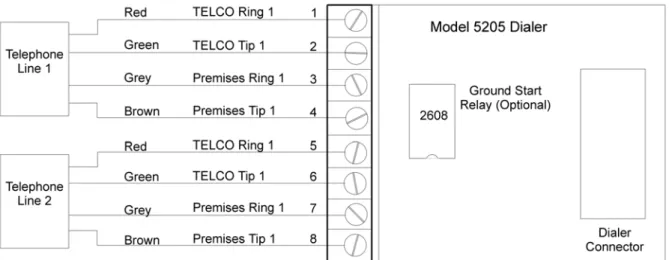
5.7
Model 5205 Dialer and Telephone Line
Connection (Optional)
The Model 5205 Dialer Module enables the 5204 to function as a communicator panel and provides the following features:
• Optional two-number dialing with same or different account codes and reporting formats. Alarms, troubles, disables, and tests can be programmed to report to either or both num-bers.
• Programmable as rotary-only or as rotary/Touch-Tone dialing.
• Ring Detect feature on line 1 for downloading data to panel from a remote computer site. • Transient voltage protection of phone lines.
• Automatic daily test (programmable from Model 5230 annunciator, built-in touchpad, or remote site via downloading option).
• Optional ground start operation (not for use on UL systems). • Compatibility with the following UL fire listed receivers:
Installation
To meet NFPA 72 Central Station Fire Alarm Systems requirements, both telephone lines must be installed.
Connect the 5205 to the phone line using an RJ31X type phone jack. The telephone company will install an RJ31X jack upon request.
The 5205 comes with stand-offs that you can place into the four holes just left of the built-in touchpad on the 5204 panel. To connect the 5205 to the 5204, make sure the dialer connector
Receiver Formats it will Receive
Silent Knight Model 9000 All formats listed in Section 10 Osborn & Hoffman Quickalert All formats listed in Section 10
Ademco 685 All tone burst formats (3/1 1400 Hz)
FBI CP220 3/1 and 4 + 2 formats
pins are positioned correctly before pressing the 5205 onto the stand-offs.
Figure 5-3 Model 5205 Dialer/Telephone Connection
Ring Detect Circuit
If the installing company calls the 5204 to up- or download data to or from a remote computer, the built-in ring detect circuit on line 2 will detect the ring. After the programmed number of rings (Step 55 in Section 8), it seizes the line and allows the transfer of data.
The 5204 has built-in dual phone line monitors. These circuits will detect any fault in the phone lines by monitoring the DC voltage present on the lines. They feature a delay of approximately 40-90 seconds before a line fault is reported as a trouble. When a fault is detected, the audible trouble signal will sound and the trouble will be reported to the central station over the remaining phone line.
A situation could occur where both phone lines appear to be good, but the dialer cannot get through to the central station on the first line. In this case, the 5204 will switch phone lines and attempt the call again using the second line.
Note: To comply with industry standards, this product is equipped with line seizure. Any time the system’s dialer needs to communicate with the central station, it will not be possible to use any telephones that are on the same line(s) as the fire system. Normally, this condition will last approximately one minute, but under ad-verse telephone circuit conditions, could last for as long as 15 minutes.
Control Panel Installation
5.8
Cable Connectors
Status (P1)
Connects the Model 4180 display model to the 5204.
Model 5230 (P2)
Can be used to temporarily connect the Model 5230 Remote Annunciator to the 5204 for programming or troubleshooting.
Note: A quick connect program cable (P/N 130294) can be ordered separately for this connection.
Power Supply (AC) Connector (P4)
Connects the 5204 control panel to the power supply.
Warning!
Do NOT use connector P2 for permanent installation. If the annunciator is to be installed permanently, it MUST be wired to the 5204 terminal block (see Section Wiring the 5230 Remote Annunciator).
Section 6
Compatible Product Installation
6.1
Zone Wiring
This manual refers to fire zone types using the latest NFPA standard designations. If you have questions about the class or style, refer to the NFPA 72 National Fire Alarm Code, 1993
Edition.
Note: For purposes of this manual, a normally open device is one with contacts that conduct when in the alarm condition and do not conduct in the non-alarm condition.
The 5204 features four fully supervised, class B (style B) fire zones (also known as loops). All four zones have ground-fault detection and are protected against transient voltages. Each zone consists of a two-wire circuit that detects the occurrence of an open in the loop, but may not be able to detect an alarm after such an occurrence. A short across the EOL resistor of the loop will cause an alarm to sound and the 5204 will report the trouble to the central station (if programmed to do so). An open or short to ground is a trouble condition. Use only normally open initiating devices for class B (style B) fire zones.
Zones 17 through 26 are class B (style B) fire zones. Figure 6-1 shows how to wire a class B loop. One side of each class B loop will connect to a zone input terminal and the other side of each loop will connect to smoke power. At the end of each class B (style B) loop, you must install a Model 7628 4.7K-ohm EOL resistor.
Figure 6-1 Model 5204 Class B (style B) Loops (Normally Open Sensors Only)
6.1.1
Four-Wire Smoke Detector Connection
Figure 6-2 illustrates how a UL listed four-wire smoke detector must be connected to a class B (style B) zone.
When wiring a four-wire smoke detector to class B (style B) zones, you must use a power supervision unit. The recommended device is an ESL 204 -12/24 V. The 7628 EOL resistor and the ESL 204 must be installed at the last detector in the loop.
Figure 6-2 Four-Wire Smoke Detector Wiring
Table 6-1 shows other four-wire smoke detectors that can be used with the 5204 panel:
Table 6-1: Compatible Four-Wire Smoke Detectors
Manufacturer Model Name/Number 12 or 24 Volt Panel
Detection Systems DS200/DS200HD Both
MB200 Both
ESL 445 Series Both
449 Series Both
GENTEX
624 24
812 12
824 24
2040-12 Power Supervision Unit 12
2040-24 Power Supervision Unit24 24
System Sensor 1851B Both 2851/2851BTH Both DH400ACDC 24 or AC Model 160150 Supervision Module
Compatible Product Installation
6.1.2
Two-Wire Smoke Detector Connection
Figure 6-3 shows how to connect two-wire smoke detectors to class B (style B) zones.
Figure 6-3 Two-Wire Smoke Detector Wiring
Table 6-1 and show the two-wire smoke detectors that are approved for use with the 5204.
Notes for Both Tables
1. If a separate base is used with a detector, the model number is shown in parentheses in the Model column.
2. In the Type column, I = Ionization, P = Photoelectric, D = Duct 3. ID = Detector (Base) Identifiers
4. Control unit Smoke Reset Time must be programmed for a number greater than or equal to the maximum reset time of the smoke detector (last column of chart).
5. The maximum number of smoke detectors per zone is determined by both the current draw and the impedance of the smoke detector. If too many smoke detectors are used on any zone, false alarms could occur.
Note: The 5204 contains a programmable smoke reset time. Be sure to program the panel to meet the reset time of the detectors.
Table 6-2: Compatible 12-Volt Smoke Detectors Voltage range: 9.5 VDC - 14 VDC: Identifier: 12C
Manuf. Model Type *ID 5204 (Max. per Loop) Smoke Det.Reset Time Detection Systems DS200 (MB200-2W) P D 15 1 sec. DS200HD (MB200-2W) P D 15 1 sec. DS250 (MB2W or MB2WL) P B (A) 11 1 sec. DS250TH (MB2W or MB2WL) P B (A) 11 1 sec. DS250HD (MB2W or MB2WL) P B (A) 11 1 sec. ESL 425C P S10 20 1 sec. 425CT P S10 20 1 sec. 425CR P S10 20 1 sec. 425CRT P S10 20 1 sec.
429C (S10A) P S10A 12 1 sec.
429CT (S10A) P S10A 12 1 sec.
429CRT (S11A) P S11A 12 1 sec.
429CST (S11A) P S11A 12 1 sec.
611U (601U) P S10 (S00) 24 1 sec.
611UD (601U) D S10 (S00) 24 1 sec.
611UT (610U) P S10 (S00) 24 1 sec.
612U (601U) I S10 (S00) 24 1 sec.
612U (601U) D S10 (S00) 24 1 sec.
612UD (601U) P S10 (S03) 24 1 sec.
611U (602U) D S10 (S03) 24 1 sec.
611UD (602U) P S10 (S03) 24 1 sec.
611UT (602U) I S10 (S03) 24 1 sec.
612UD (602U) D S10 (S03) 24 1 sec.
System Sensor 1451 (B401B) I A 10 6 sec. 1800 I A 12 0.9 sec. 1851B (B101B) ID A 10 2 sec. 1851DH (DH1851DC) ID A 10 2 sec. 2151 (B110LP) P A 10 .3 sec. 2400 P A 10 6 sec. 2400 (DH400) P A 10 1 sec. 2400TH P A 10 6 sec. 2451 (B401B) P A 10 1 sec. 2451TH (B401B) P A 10 6 sec. 2800 P A 10 6 sec. 2800TH P A 10 6 sec. 2851B (B101B) PD A 10 2 sec. 2851TH (B101B) PD A 10 2 sec. 2851DH (DH2851DC)I PD A 10 2 sec.
Compatible Product Installation
Note: Note: The 5204 contains a programmable smoke reset time. Be sure to program the panel to meet the reset time of the detectors.
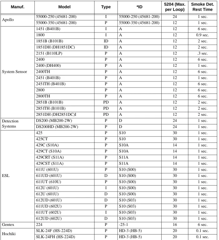
Table 6-3: Compatible 24-Volt Smoke Detectors Voltage range: 9.5 VDC - 14 VDC: Identifier: 12C
Manuf. Model Type *ID 5204 (Max. per Loop) Smoke Det. Rest Time Apollo 55000-250 (45681-200) I 55000-250 (45681-200) 24 1 sec. 55000-350 (45681-200) P 55000-350 (45681-200) 12 1 sec. System Sensor 1451 (B401B) I A 12 6 sec. 1800 I A 12 0.9 sec. 1851B (B101B) ID A 12 2 sec. 1851DH (DH1851DC) ID A 12 2 sec. 2151 (B110LP) P A 12 .3 sec. 2400 P A 12 6 sec. 2400 (DH400) P A 12 1 sec. 2400TH P A 12 6 sec. 2451 (B401B) P A 12 1 sec. 2451TH (B401B) P A 12 6 sec. 2800 P A 12 6 sec. 2800TH P A 12 6 sec. 2851B (B101B) PD A 12 2 sec. 2851TH (B101B) PD A 12 2 sec. 2851DH (DH2851DC)I PD A 12 2 sec. Detection Systems DS200 (MB200-2W) P D 24 1 sec. DS200HD (MB200-2W) P D 24 1 sec. ESL 425 P S10 30 1 sec. 425CT P S10 30 1 sec.
429C (S10A) P S10A 14 1 sec.
429CT (S10A) P S10A 14 1 sec.
429CRT (S11A) P S11A 14 1 sec.
429CST (S11A) P S11A 14 1 sec.
611U (601U) P S10 (S00) 30 1 sec.
611UD (601U) D S10 (S00) 30 1 sec.
611UT (610U) P S10 (S00) 30 1 sec.
612U (601U) I S10 (S00) 30 1 sec.
612U (601U) D S10 (S00) 30 1 sec.
612UD (601U) D S10 (S03) 30 1 sec.
611UD (602U) P S10 (S03) 30 1 sec.
611UT (602U) I S10 (S03) 30 1 sec.
612UD (602U) D S10 (S03) 30 1 sec.
Gentex 224 P -25-1 16 6 sec.
Hochiki SLK-24F (HS-224D) P HD-3 (HB-5) 20 0.1 sec.
6.2
Connections to Compatible Silent Knight
Products
This section describes the connections of the following Silent Knight products:· • Model 4180 Status Display Module (see Section 6.2.1)
• Model 5220 Direct Connect Module (see Section 6.2.2) • Model 5230 Remote Annunciator (see Section 6.2.3) • Model 5395 Distributed Power Module (see Section 6.2.4) • Model 5205 Dialer Module (see Section 5.7)
• Model 7181 Zone Converter (see Section 6.2.5)
Note: Once you have installed the 5204 and, if applicable, the 5230 and the 4180, test the basic system. Apply power, test the touchpad, then remove the power. Wire each auxiliary device with the power off. After you install each device, test it by re-applying the power. When you power up the 5204, the two dots on the built-in touchpad display will alternately flash on and off.
Note also that there is a 2-second power-up delay on the 5230.
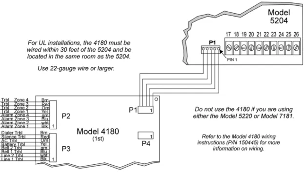
6.2.1
Model 4180 Status Display Module
The Model 4180 Status Display module provides remote annunciation of alarm and trouble status information for each zone.
The 4180 has 2 connectors, each of which has 8 outputs available for annunciation. These outputs are active high at +12 VDC. Each output can provide up to 100 mA of current, with a total limitation of 175 mA (when used with the 5204). The module has 4 normally open relays that are nondedicated, and therefore can be wired to be active with any of the outputs. The 4180 is not supervised. Table 6-4 shows the system status indicated by each LED.
Do not use the 4180 relays in a 12 V 5204 installation.
Table 6-4: Model 4180 Connection
Connector P2 System Status Connector P3 System Status
1 Alarm 1 1 Line #1 Trouble
2 Alarm 2 2 Line #2 Trouble
3 Alarm 3 3 Bell #1 Trouble
4 Alarm 4 4 Bell #1 Trouble
5 Trouble 1 5 Battery Trouble
6 Trouble 2 6 AC Trouble
7 Trouble 3 7 Silence Trouble
Compatible Product Installation
Figure 6-4 Model 4180 Connection
When using a 4180, maintain a physical separation of one-half inch or more between field wires and connection points to prevent damage from transients.
6.2.2
Model 5220 Direct Connect Module
The 5220 Direct Connect Module can be used with the 5204 to meet NFPA 72 Remote Signaling or Local Protective Signaling standards. The 5220 requires four connections to the 5204 and provides outputs for direct connect (city box) and polarity reversal.
To meet the 60-hour standby power requirements for NFPA 72 systems, normal standby currents are de-rated. See Section 4.2 for these current values.
6.2.2.1 Installation
Locate the knockout on the right side of the 5204 cabinet to connect the 5220 using a short piece of conduit (must not exceed 20 feet in length).
A four-wire pigtail is provided to wire the 5220 to the 5204. Figure 6-5 shows how to wire the Model 5220 Direct Connect module. The wiring chart uses bell #2 as the initiating loop. Program bell #2 to be active for the events to be reported.
Figure 6-5 Model 5220 Wiring Diagram
6.2.2.2 City Box Connect (24 VDC Systems Only)
(For NFPA 72 Auxiliary Protected Fire Alarm systems for fire alarm service.)
With the 5220, you can connect the 5204 directly to a municipal fire alarm box or "city box." The city (master) box is an enclosure that contains a manually operated transmitter used to send an alarm to the municipal communication center, which houses the central operating part of the fire alarm system. To ensure communication of an active alarm status, use the 5220 only with 5204 24 V systems when connected to a series type DC master box.
Wire the 5220 to the 5204 as shown in Figure 6-5. Wire the city box coil to terminals 3 and 4 in the 5220. Maximum coil and wire resistance (combined) is 30 ohms.
It is not possible to reset the remote indication until you clear the condition and reset the 5204 panel.
Select relay 2 for 5220 city box. When you select 5220 operation, bell 2 and relay 2 cannot be used for any other purpose.
Compatible Product Installation
6.2.2.3 NFPA 72 Polarity Reversal (12 or 24 VDC Systems)
The 5220 provides a current that reverses polarity during an alarm or removes current during a trouble condition.
Wire the 5220 for polarity reversal as shown in Figure 6-6.
Figure 6-6 Wiring the 5220 for Polarity Reversal
Alarms will override trouble conditions, and it will not be possible to reset the remote indication until you clear the condition and reset the 5204 panel.
Select relay 2 for 5220 Direct Connect. When you select 5220 operation, bell 2 and relay 2 cannot be used for any other purpose.
Any trouble condition will cause a trouble to be sent. Any zone programmed to activate bell 2 will cause an alarm to be sent.
6.2.3
Model 5230 Remote Annunciator
The Model 5230 Remote Annunciator is an optional touchpad (keystation) you can use for English-language programming. The 5230 also provides trouble and alarm information. When programming the 5204, be sure to select the correct number of supervised annunciators (see Section 8.4.3).
6.2.3.1 Setting ID Codes
Before permanently installing the Model 5230 Remote Annunciator, you must first set its identification codes. Each annunciator to be supervised must be given its own identification codes. The ID numbers must start at 1 and progress sequentially to 3 (3 annunciators max.).
On the back of each annunciator is a small 4-position dip switch you can use to set the ID code. Table 6-5 shows the positions (up or down) of the various switches for specific ID codes.
6.2.3.2 Wiring the 5230 Remote Annunciator
A 4-position terminal block is provided with the Model 5230 Annunciators to connect them to the 5204. Figure 6-7 shows the wiring for the Model 5230.
Table 6-5: Model 5230 Dip Switch Settings
ID Number Switches 1 2 3 4 0 * Up Up Up Up 1 Down Up Up Up 2 Up Down Up Up 3 Down Down Up Up * Not Supervised
Compatible Product Installation
6.2.3.3 Mounting the 5230 Remote Annunciator
For UL installations, the 5230 Remote Annunciators must be mounted on a dual gang electrical box.
To mount the annunciator, you must first remove the rear mounting plate.
To do this, insert a #4 flat blade screwdriver into the slots located on the bottom edge of the annunciator. Gently turn the screwdriver until the mounting plate pulls away from the frame. Once you remove the mounting plate, you can secure it to the wall using #6 or #8 screws. The mounting plate should be oriented so that the word TOP is toward the top of the plate and facing you. Through the square hole in the mounting plate, run the wiring to the annunciator. When all of the wires are connected to the annunciator, set the top of the annunciator over the tabs on the top of the mounting plate. Make sure the wires are not pinched between the frame and the mounting plate. Press each corner of the bottom side onto the annunciator mounting plate until you hear it click into place.
Note: You may have to gently squeeze the annunciator (top to bottom) to align it while snapping the bottom edge into place.
6.2.4
Model 5395 Distibuted Power Module
Figure 6-8 shows you how to connect the Model 5395 to the Model 5204 panel.
6.2.5
Model 7181 Zone Converter
The Model 7181 Zone Converter adapts the 5204 class B (style B) zones so that they can be connected to class A (style D) initiating devices. Figure 6-9 shows a typical installation. Refer to the Model 7181 Installation Manual (P/N 150632) for further information.
Compatible Product Installation
6.3
Supervised Notification Device Outputs
Note: To reduce the possibility of false alarms and transient damage, DO NOT bundle telephone wires together with notification device or zone wires.
The 5204 provides two supervised notification device outputs to annunciate alarm conditions. These outputs can be programmed for each individual zone. For proper operation, you must use polarized notification devices with a model 7628 4.7K ohm end-of-line (EOL) resistor on each loop. See Figure 6-10 for connection to the 5204 panel.
Figure 6-10 Model 5204 Notification Device Connections
The UL listed sounding appliances that can be used with the 5204 are listed in Table 6-6 and Table 6-7.
Table 6-6: Compatible 12-Volt Notification Devices
Manufacturer Model Number Device Type
Federal Signal VALS Strobe
450-D Horn Gentex HG124 Horn SHG12L Horn Strobe SHG12H Horn Strobe Wheelock 34T-12-R Alarm Horn 462-G10-12-R Bell 7001T-12-R Mini-Horn 7001T-12-W Mini-Horn 7001T-12W-FR Strobe Horn 7002T-12-W-FR Strobe Horn MB-G6-12-R Motor Bell MB-G10-12-R Motor Bell
MBS-G6-12-W-HF-R Motor Bell with Strobe
MBS-G10-12-W-HF-R Motor Bell with Strobe
MIZ-12-R Mini-Horn
MIZ-12-W Mini-Horn
MIZ-12-WS-VF-R Mini-Horn/Strobe
MT-12/24-R Strobe Horn
Table 6-7: Compatible 24-Volt Notification Devices
Manufacturer Model Number Device Type
Faraday
446X 12/24VDC Vibrating Bell 476X 12/24VDC Vibrating Bell 477X 12/24VDC Single Stroke Bell 5303B-0-14-( )-DC Chime (flush) 5304B-0-14-( )-DC Chime (surface) 5305B-0-4-( )-DC Chime (ceiling) 5306B-0-14-( )-24-DC Chime/Strobe (flush) 5307B-0-14-( )-24-DC Chime/Strobe (surface) 5308B-0-4-( )-24-DC Chime/Strobe (ceiling) 5333B-0-14-24-DC Multi-Tone Horn (flush) 5334B-0-14-24-DC Multi-Tone Horn (surface) 5336B-( )-14-24-DC Multi-Tone Horn/Strobe (flush) 5337B-( )-14-24-DC Multi-Tone Horn/Strobe (surface) 5338B-( )-4-24-DC Multi-Tone Horn/Strobe (ceiling) 5343B-0-14-24-DC Single Tone Horn/Strobe (flush) 5344B-0-14-24-DC Single Tone Horn/Strobe (surface) 5345B-0-4-24-DC Single Tone Horn/Strobe (ceiling) 5348B-( )-4-24-DC Single Tone Horn/Strobe (ceiling) 5373B-0-14-(12 or 24)-DC 8-Tone Horn/Strobe (flush) 5374B-0-14-(12 or 24)-DC 8-Tone Horn/Strobe (surface) 5375B-0-4-(12 or 24)-DC 8-Tone Horn/Strobe (ceiling) 5376B-0-14-24-DC 8-Tone Horn/Strobe (flush) 5377B-0-14-24-DC 8-Tone Horn/Strobe (surface) 5378B-0-4-24-DC 8-Tone Horn/Strobe (ceiling) 5405B-0-14-24-DC Sync Control Unit
5508B-( )-14-24-DC Single Gang Sync Strobe (flush) 5521B-( )-14-24-DC 4” Square Sync Strobe (surface) 5522B-( )-14-24-DC 4” Square Sync Strobe (flush) 6126B-U-14-24 VDC Horn/Strobe
6223B-0-14-24-DC Horn (flush) 6224B-0-14-24-DC Horn (surface) 6225B-0-4-24-DC Horn (ceiling)
Compatible Product Installation
Faraday (continued)
6228B-( )-4-24-DC Horn/Strobe (ceiling)
6243B-0-14-24-DC Electron-Mechanical Horn (flush) 6244B-0-14-24-DC Electron-Mechanical Horn (surface) 6245B-0-4-24-DC Electron-Mechanical Horn (ceiling) 6246B-( )-14-24-DC Electron-Mechanical Horn/Strobe (flush) 6247B-( )-14-24-DC Electron-Mechanical Horn/Strobe (surface) 6248B-( )-4-24-DC Electron-Mechanical Horn/Strobe (ceiling) 6300B-0-14-24-DC Mini-Horn (flush) 6301B-0-14-24-DC Mini-Horn (surface) 6302B-( )-4-24-DC Mini-Horn (ceiling) 6310B-0-14-24-DC Mini-Horn/Strobe/Strobe (flush) 6311B-0-14-24-DC Mini-Horn/Strobe/Strobe (surface) 6312B-( )-14-24-DC Mini-Horn/Strobe/Strobe (ceiling) 6320B-0-14-24-DC Sync Mini Horn/Strobe (1 gang) 6321B-0-14-24-DC Sync Mini Horn/Strobe (1,2 gang) 6322B-( )-14-24-DC Mini Horn/Sync Strobe (1,2 gang,
4SQ) Federal Signal 450 Horn VALS Horn/Strobe Gentex GX90-4 Horn GXS-4-15-1 Strobe GXS-4-1575 Strobe GX90S-4-15 Horn GX90S-4-1575 Horn HG124 Horn SHG24-1575 Horn/Strobe SHG24-15 Horn/Strobe GMH-24-X Horn GMS-24-X Horn/Strobe GMS-24-X Horn/Strobe G0T24 Horn G0S24-X Horn
Table 6-7: Compatible 24-Volt Notification Devices
System Sensor MASS241 Horn/Strobe MASS24110ADA Horn/Strobe MASS2415ADA Horn/Strobe MASS2475ADA Horn/Strobe SS1215ADA Strobe SS4110ADA Strobe SS2415ADA Strobe SS2475ADA Strobe PS2415ADA Mini-Horn/Strobe PS241575ADA Mini-Horn/Strobe PS24110ADA Mini-Horn/Strobe PS2475ADA Mini-Horn/Strobe Wheelock 46T-G4-24-R Bell 46T-G6-24-R Bell 46T-G10-24-R Bell 46T-G6-24-WS-24-HF-R Strobe/Bell 46T-G10-24-WS-24-HF-R Strobe/Bell 46T-G6-24-WH-24-HF-R Strobe/Bell 46T-G10-24-WH-24-HF-R Strobe/Bell 7001T-12\24-W-FR Strobe Horn 7002T-12\24-W-FR Strobe Horn
AES-DL1-R Multitone Horn AES-EL1-R Multitone Horn AES-DL1-WS-24-VF-R Multitone Horn
AES-EL1-WS-24-VF-R Multitone Horn AES-DL1-WH-24-VF-R Multitone Horn AES-EL1-WH-24-VF-R Multitone Horn AES-DL1-WM-24-VF-R Multitone Horn AES-EL1-WM-24-VF-R Multitone Horn AH-24-R Horn
AMT-12\24-R Strobe Horn AMT-24-LS-VFR Strobe Horn AMT-24-LSM-VFR Strobe Horn AMT-24-IS-VFR Strobe Horn
Table 6-7: Compatible 24-Volt Notification Devices
Compatible Product Installation
Wheelock (cont.)
AS-2430-VFR Strobe Horn AS-2475-VFR Strobe Horn AS-24110-HFR Strobe Horn SM-12\24-R Strobe Horn Controller DSM-12\24-R Strobe Horn Controller CF-BF1 Chime CF-BF1-R Chime CH-CF1 Chime CH-CF1-R Chime CH-CF1-W Chime CH-DF1 Chime CH-DF1-R Chime CH-BF1-WS-24-HF-R Strobe Chime CH-CF1-LS-24 Strobe Chime CH-CF1-MS-24 Strobe Chime CH-CF1-IS-24 Strobe Chime CH-CF1-LS-24-CFW Strobe Chime CH-CF1-MS-24-CFW Strobe Chime CH-CF1-IS-24-CFW Strobe Chime CH-CF1-WS-24-CF-W Strobe Chime CH-DF1-LS-24 Strobe Chime CH-DF1-MS-24 Strobe Chime CH-DF1-IS-24 Strobe Chime CH-DF1-LS-24-VFR Strobe Chime CH-DF1-LSM-24-VFR Strobe Chime CH-DF1-MS-24-VFR Strobe Chime CH-DF1-IS-24-VFR Strobe Chime CH-DF1-WM-24-VFR Strobe Chime CH-DF1-WS-24-VF-R Strobe Chime
DSM-12/24 Sync Module EH-DL1-R Electronic Horn EH-EL1-R Electronic Horn Electronic Horn
EHS-DL1-W-VF-R Strobe Horn (single input) EHS-EL1-W-VF-R Strobe Horn (single input)
Table 6-7: Compatible 24-Volt Notification Devices
Wheelock (cont.)
EH-DL1-WH-24-VF-R Strobe Horn (dual input) EH-EL1-WH-24-VF-R Strobe Horn (dual input) EH-DL1-WM-24-VF-R Strobe Horn (dual input) EH-EL1-WM-24-VF-R Strobe Horn (dual input) HSW-24-HFR Remote Strobe HS2W-24-HFR Remote Strobe HSPW-24-HFR Remote Strobe IS-24-VFR Remote Strobe IS1-24-VFR Remote Strobe IS3-24-VFR Remote Strobe ISP-24-HFR Remote Strobe LS-24-VFR Remote Strobe LS1-24-VFR Remote Strobe LS3-24-VFR Remote Strobe LSP-24-HFR Remote Strobe LSM-24-VFR Remote Strobe LS1M-24-VFR Remote Strobe LS3M-24-VFR Remote Strobe LSPM-24-VFR Remote Strobe MS-24-VFR Remote Strobe MS1-24-VFR Remote Strobe MS3-24-VFR Remote Strobe MSP-24-HFR Remote Strobe MB-G6-24-R Motor Bell MB-G10-24-R Motor Bell MBS-G6-24-W-HF-R Motor Bell with Strobe MBS-G10-24-W-HF-R Motor Bell with Strobe MIZ-24-R Mini-Horn MIZ-24-W Mini-Horn MIZ-24-LS-VFR Mini-Horn/Strobe MIZ-24-LSM-VFR Mini-Horn/Strobe MIZ-24-MS-VFR Mini-Horn/Strobe MIZ-24-HSW-HFR Mini-Horn/Strobe MIZ-24-IS-VFR Mini-Horn/Strobe
Table 6-7: Compatible 24-Volt Notification Devices
Compatible Product Installation Wheelock (cont.) MIZ-24-WH-VF-W Mini-Horn/Strobe MIZ-24-WM-VF-W Mini-Horn/Strobe MT-12/24-R Strobe Horn MT-24-LS-VFR Strobe Horn MT-24-LSM-VFR Strobe Horn MT-24-MS-VFR Strobe Horn MT-24-IS-VFR Strobe Horn MT-24-SL-VFR Strobe Horn
MT-24-SLM-VFR Synch. Multitone Strobe MT-24-WM Strobe MT-24-WM-VF-R Horn MT-24-WM-VFR Horn RS-2415-HFR Strobe RSP-2415-VFR Strobe RS-241575-VFR Strobe RSP-241575-VFR Strobe RS-2430-VFR Strobe RS-2430-HFR Strobe RS-2475-VFR Strobe RSP-2475-HFR Strobe RS-24110-HFR Strobe RSP-24110-HFR Strobe
SL-24-VFR Synchronized Remote Strobe SL1-24-VFR Synchronized Remote Strobe SL3-24-VFR Synchronized Remote Strobe SLP-24-VFR Synchronized Remote Strobe SLM-24-VFR Synchronized Remote Strobe SL1M-24-VFR Synchronized Remote Strobe SL3M-24-VFR Synchronized Remote Strobe SLPM-24-VFR Synchronized Remote Strobe SHW-24-VFR Synchronized Remote Strobe SH2W-24-VFR Synchronized Remote Strobe SHPW-24-VFR Synchronized Remote Strobe SCM-24-R Controller for Synchronized Strobes
Table 6-7: Compatible 24-Volt Notification Devices
6.4
Auxiliary Relays
The 5204 provides two auxiliary relay outputs. Relay #2 output annunciates fire alarms. Relay #2 can be programmed to annunciate either alarm or trouble conditions, or can be used to activate the Model 5220 Direct Connect Module. Figure 6-11 shows the relay contact connections.)
• Fire alarm
• The Model 5220 Direct Connect Module (see Section 6.2.2). • Trouble Conditions (any system trbl.)
Wheelock (cont.) SRP-2415-HFR Sync Strobe SR-241575-VFR Sync Strobe SRP-241575-VFR Sync Strobe SR-2475-VFR Sync Strobe SR-2475-HFR Sync Strobe SR-24110-HFR Sync Strobe SRP-24110-HFR Sync Strobe V7001T-12\24-W-FR Strobe Horn WM3T-24-FR Remote Strobe WM3T-24-VFR Remote Strobe WS1T-24-FR Strobe WS3T-24-FR Strobe WST-24-FR Strobe
Table 6-7: Compatible 24-Volt Notification Devices
Compatible Product Installation
Figure 6-11 Auxiliary Relays
6.5
External Silence Keyswitch (Optional)
For manual silencing or resetting alarms, you can attach a remote keyswitch to the 5204 at terminal #6. Use a UL listed keyswitch. The keyswitch will operate as Normally Open Momentary at 24 VDC/.25 A minimum.
Once the keyswitch has been wired, it must be programmed either to silence or reset alarms (see Section 8.4.1.). If programmed to silence, the keyswitch turns off an annunciator that is signaling a trouble or alarm condition.
If programmed to reset alarms, the keyswitch removes smoke detector power for a
programmed length of time (see Section 8.4.1). This allows the smoke detector to sense new alarm conditions.
Figure 6-12 Wiring an External Silence or Reset Alarms Keyswitch
Section 7
Normal Operation
The optional Model 5230 Remote Annunciator provides annunciation of trouble and alarm conditions, and can be used to program the system. Key functions for both the Model 5230 (Figure 7-1) and the 5204 built-in touchpad (Figure 7-2) are described in Section 7.1. Section 8 explains how to program the 5204 using the Model 5230.
Figure 7-1 Model 5230 Remote Annunciator
The Model 5230 Remote Annunciator has a liquid crystal display (LCD) for displaying English-language messages. If the 5204 is not being programmed, the LCD cycles through all messages that are applicable at the time, showing a different one every 1.5 seconds. Refer to Section 9.3 for more information on troubleshooting messages.
When AC power is being supplied, and the battery is fully charged, the POWER LED glows steadily. If the POWER LED is flashing, the AC power has been removed or the backup battery is low. If neither AC nor battery power is being supplied, the POWER LED is off. The audio transducer buzzer produces short beeps to annunciate keystrokes. It also emits a long, high-pitched tone to denote a trouble condition or to indicate that an annunciator function has been entered incorrectly (see Section 7.1).
Figure 7-2 Built-in Touchpad
7.1
Built-in Touchpad and Model 5230 Annunciator
Operation
To operate the 5204, you must use either the built-in touchpad or the Model 5230 Remote Annunciator. This annunciator functions the same as the internal touchpad except for the STEP key. The installer uses this key to step through programming options (see Section 8.3). Following are the basic operating functions. Note that if no keys are pressed for 15 minutes while in program mode, the system will time out and resume normal operation.
The message TRY AGAIN appears on the 5230 display if you do not press any keys for 5 seconds while accessing a function, or, if you attempt to access a function before exiting from another function.
In the following table, Code 0 refers to the installer’s code (factory programmed as 5204). Code 1 refers to the operator’s code (factory programmed as 1111). These two codes are described in Step 45 and Step 46 of Step Programming (see Section 8.4.1).
Normal Operation
Note: A valid operating code is always required when using the 5230.
Table 7-1: Touchpad Operations
To:
Press:
Additional Information 5230 Annunciator Built-in Touchpad
Clear Enables you to start again if you
enter the wrong keystrokes. If you enter a function incorrectly on the 5230, the annunciator’s PZT buzzer will emit a long, high-pitched tone.
Test the system
+ code 0 or 1
The system will test the 4180 outputs, the built-in touchpad LED display, signaling devices, sirens, and communicator.
Reset alarms (or smoke
detectors) + code 0 or 1 + code 0 or 1
After a smoke alarm has been triggered, this function removes smoke detector power for the programmed length of time (as determined by the smoke detector). This allows the smoke detector to sense new alarm conditions.
When a trouble condition occurs and you reset the alarm, the trouble condition is stored in memory until you clear the alarm memory. If you do not clear the alarm memory, the trouble condition is displayed the next time a trouble condition occurs, implying incorrectly that more than one trouble condition exists.
Clear alarm memory
+ code 0 or 1
Clears all data out of alarm memory and resets the 4180. (This function removes all memory of alarms.) Reset the dialer
+ code 0 + code 0
Aborts an in-progress call to the central station.
Initiate download
+ code 0 + code 0
Starts the downloading process. Exit the DOWNLOADING mode by pressing CLEAR CLEAR. Display alarm
memory
+ code 0 or 1
Displays the current alarm memory. (It is recommended that you clear alarm memory after displaying it.)
Display troubles
+ code 0 or 1
Displays trouble conditions.
Silence trouble or alarm condi-tions
+ code 0 or 1
Silences signaling devices that are in trouble or alarm. (On-board beeper and local annun-ciators continue to sound until serviced. See Section 9.1 for more details.) CLEAR CLEAR 0 TEST ENTER 0 TEST ENTER 1 RESET ALARM ENTER 1 RESET ALARM ENTER CLEAR 2
MEMORY ENTER CLEAR 2 MEMORY ENTER
DIAL. 3
RESET ENTER DIAL. 3 RESET ENTER 4 LOAD ENTER 4 LOAD ENTER DISPLAY 5 MEMORY ENTER DISPLAY 5 MEMORY ENTER DISPLAY 6 TRBL. ENTER DISPLAY 6 TRBL. ENTER SILENCE STEP SILENCE
Fire drill
+ code 0 or 1
To end a fire drill:
+ code 0 or 1
+ code 0 To end a fire drill:
Causes the system to sound an alarm and report a FIRE TEST.
Set time Enter time in military time..
The SET MODE LED will turn on and the built-in touchpad display will flash 9- indicating that you are in the SET TIME mode.
Note: The 5204 powers up in the SET TIME mode, with 9- showing on the display. If you wish to set the time at this point, it is not necessary to press the 9 ENTER (code) key sequence. Simply key in the appropriate digits. To exit the SET TIME mode, press ENTER.
Disable/Enable (shunting / un-shunting) (Zone #1-4) + + code 1 or 0 (Zone #1-4) + + code 1 or 0
Disables a zone (prevents it from responding to an alarm condition) or reactivates a dis-abled zone. When you disable, a trouble buzzer will sound.
Note: If the dialer is busy, modes 22, 25, and 27 are disabled. If you are in mode 22, 25, or 27, the dialer is disabled. Walk test
+ code 0 (factory programmed as 5204) To exit press: . + code 0 (factory programmed as 5204) To exit press: .
Enables you to test the system. When you enter this mode, the LCD will indicate that you are in the Walk Test mode. When a zone is violated, the signaling device outputs will become ac-tive for approximately 6 sec-onds. Zone Trouble-shooting mode + code 0 To exit press: . + code 0 To exit press: .
Enables you to locate and cor-rect problems. The use of this mode is described in Section 9.2.2.
Table 7-1: Touchpad Operations
To:
Press:
Additional Information 5230 Annunciator Built-in Touchpad
CLEAR 2 MEMORY 0 TEST ENTER SILENCE STEP CLEAR 2 MEMORY 0 TEST ENTER SILENCE SET 9
TIME ENTER SET
9 TIME ENTER DISABLE SHIFT DISABLE CLEAR 2 MEMORY CLEAR 2 MEMORY ENTER SILENCE STEP SILENCE STEP CLEAR CLEAR CLEAR 2 MEMORY CLEAR 2 MEMORY ENTER
SILENCE SILENCE CLEAR CLEAR
CLEAR 2 MEMORY DISPLAY 5 MEMORY ENTER SILENCE STEP SILENCE STEP CLEAR CLEAR CLEAR 2 MEMORY DISPLAY 5 MEMORY ENTER
Normal Operation
7.1.1
Operating Modes
The following table describes which codes can access operating modes during alarms:
7.1.2
Built-in Touchpad Display Codes
The built-in touchpad display shows the zones in which a trouble or alarm condition is occurring. It also displays two-digit codes that represent a variety of conditions, as an aid in troubleshooting the system. These codes are listed below.
Step Program-ming mode + code 0 To exit press: . + code 0 To exit press: .
Enables you to program 5204 options stored on the EE-PROM. Refer to Section 8.3 for instructions on using mode 27. Operating Mode Allowed During Alarm Code Required On 5230 On Built-in Touchpad
00 System test No Code 0 or 1 None
01 Reset alarm Yes Code 0 or 1 Code 0 or 1
02 Clear alarm memory No Code 0 or 1 None
03 Dialer reset Yes Code 0 Code 0
04 Download No Code 0 Code 0
05 Display alarm memory No Code 0 or 1 None
06 Display troubles No Code 0 or 1 None
09 Set time No Code 0 or 1 Code 0 or 1
2B Silence mode Yes Code 0 or 1 None
20 Fire drill No Code 0 or 1 Code 0 or 1
22 Walk test No Code 0 Code 0
27 Program No Code 0 Code 0
25 Troubleshooting No Code 0 Code 0
E0 Disable/enable zone Yes Code 0 or 1 Code 0 or 1
Table 7-1: Touchpad Operations
To:
Press:
Additional Information 5230 Annunciator Built-in Touchpad
CLEAR 2 MEMORY 7 ENTER SILENCE STEP SILENCE STEP CLEAR CLEAR CLEAR 2 MEMORY 7 ENTER
The following table describes the codes that appear on the built-in touchpad:
Display Explanation
0 Fire drill (with ALARM, ALARM MEMORY, or TROUBLE LED).
1 through 4 Zone numbers (with ALARM, ALARM MEMORY, or TROUBLE LED).
A “c” in front of the number indicates a supervisory sprinkler zone.
E7 Indicates trouble with the EEPROM memory.
F0 F1 through F3
5230 annunciator power trouble.
Indicates trouble with a particular annunciator. A1 through A2 Indicates trouble with a particular bell output.
P3
P3 indicates a short between Earth Ground and Common Ground. To determine the location of the short, remove field wiring circuits until the control returns to normal operation. See Section 9.2.
P4
P4 indicates a short between Earth Ground and loop or bell power. To determine the location of the short, remove field wiring circuits until the control returns to normal operation. See Section 9.2.
P0 Indicates that the printer is out of paper. dc
Ac dF
Low battery condition. Low AC condition.
Dialer failed to communicate or Data lost during an attempt to transmit data to the central station.
L1 L2
Phone Line 1 Fault Phone Line 2 Fault -0 -2 -4 -5 -6 -7 -8 -9 Fire drill Walk test Downloading Zone test
HEX PROGRAMMING mode STEP PROGRAMMING mode SET DATE mode
SET TIME mode
Normal Operation
7.1.3
Silencing the System
To silence a trouble, press SILENCE. To silence an alarm, follow these steps:
1. Disable the zone by pressing (zone number) + DISABLE + code 1 or 0.
2. Reset the system by pressing ENTER + code 1 or 0.
3. The zone is now in trouble because of the disabled zone and can be silenced in the normal way by pressing SILENCE.
See Section 9.1 for related information.
7.1.4
LED Indicators
Six light emitting diodes (LEDs) appear in the 5204 cabinet window.
LED Status Condition
ALARM (red)
OFF No alarm condition exists.
ON A fire alarm condition exists in the zones shown on the touchpad.
SILENCED (yellow)
OFF An alarm or trouble has not been silenced.
ON An alarm or trouble condition exists and the audible annunciators have been silenced.
AC / DC (green)
OFF Panel has lost all power.
ON Panel is running on AC and battery power (normal condition).
FLASHING Panel is running on battery power only or AC power only.
MEMORY (yellow) OFF No information is stored in alarm memory.
ON An alarm condition has been reset.
TROUBLE (yellow) OFF No trouble condition exists.
ON A trouble condition exists.
SET MODE (yellow) REPORT
OFF ON
Normal operating mode and not reporting. System is in a SET (TEST or PROGRAM) mode. FLASHING System is reporting
RESET 1 ALARM
7.2
System Testing
System testing includes fire drills, zone testing, and 24-hour automatic tests.
7.2.1
Fire Drills (Mode 20)
You can run fire drills using either the built-in touchpad or the Model 5230 touchpad. To
initiate a fire drill, press ENTER + code 0 or 1. The system will sound an alarm and report a fire test. To end the fire drill, press SILENCE) + code 0 or 1.
7.2.2
Walk Test (Mode 22)
The Walk Test mode enables you to test individual sensors.
To enter the Walk Test mode, press ENTER + code 0 (factory-programmed as 5204). The LCD will indicate that you are in the Walk Test mode. When a zone is violated, the bell outputs will become active for approximately six seconds. During a walk test, smoke verification is disabled. Follow the manufacturer’s directions for testing smoke and heat detectors. To violate a waterflow detector, open the waterflow valve.
Zones can be disabled individually to facilitate testing and troubleshooting. Disabled zones will NOT be tested. If no zones are tripped during the Walk Test (or keys pressed) for 15 minutes, the system will time out and resume normal operation.
To exit Walk Test mode, press STEP STEP CLEAR CLEAR. If using the built-in touchpad, press SILENCE SILENCE CLEAR CLEAR.
7.2.3
Automatic Self Test
The Model 5204 lets you select the time of day to send the 24-hour automatic test signal to the central station.
The Auto Test (Dialer test sent automatically at specified times) also sends all unrestored events, as now required by UL. Events listed before AUTO TEST on the printout at the central station are new events. Events listed after AUTO TEST are old events that have not been restored.
7.2.4
Watchdog Circuit
During normal operation, the control microprocessor of the 5204 is constantly running programs to check inputs and carry out other routine functions. If this program stops running for some reason, the watchdog circuit will automatically attempt to resume normal operation
CLEAR 2 MEMORY 0 TEST CLEAR 2 MEMORY CLEAR 2 MEMORY