www.rsc.org/advances
RSC Advances
This is an Accepted Manuscript, which has been through the
Royal Society of Chemistry peer review process and has been
accepted for publication.
Accepted Manuscripts are published online shortly after
acceptance, before technical editing, formatting and proof reading.
Using this free service, authors can make their results available
to the community, in citable form, before we publish the edited
article. This Accepted Manuscript will be replaced by the edited,
formatted and paginated article as soon as this is available.
You can find more information about Accepted Manuscripts in the
Information for Authors
.
Please note that technical editing may introduce minor changes
to the text and/or graphics, which may alter content. The journal’s
standard
Terms & Conditions
and the
Ethical guidelines
still
apply. In no event shall the Royal Society of Chemistry be held
responsible for any errors or omissions in this Accepted Manuscript
or any consequences arising from the use of any information it
contains.
Graphical abstract
Controlled adhesion of the inner and outer interfaces of the water-in-oil-in-water double
emulsion drops and consecutive polymerization of polyurethane precursors between the
interfaces lead to the production of a mechanically resilient but flexible microshell structure.
RSC
Advances
Accepted
Journal Name
COMMUNICATION
This journal is © The Royal Society of Chemistry 20xx J. Name., 2013, 00, 1-3 | 1
Please do not adjust margins
Please do not adjust margins
Received 00th January 20xx,Accepted 00th January 20xx
DOI: 10.1039/x0xx00000x
www.rsc.org/
Uniform hydrogel-filled elastomer microcapsules structured with
mechanically resilient complex shell layers
Sang Woo Han,
aBohyun Kim,
aEun Sook Jeong,
aSinae Kim,
aand Jin Woong Kim*
, a,bWe introduce a facile and straightforward approach for the fabrication of uniform elastomer microcapsules with shells comprising a polyurethane thin elastomer membrane. Controlled adhesion of the inner and outer interfaces of the W/O/W double emulsion drops and consecutive polymerization of polyurethane precursors between the interfaces lead to the production of a mechanically resilient complex microshell.
Encapsulation of active agents, such as drugs and catalysts, is of great importance in the fields of drug delivery,1-4 bioreactors,5-7 and MOFs.8, 9 A useful platform that is also practically applicable is a vesicular system, which is typically achieved by the self-assembly of amphiphiles, including lipids,10-12 amphiphilic block copolymers,13-16
and even colloidal particles.17, 18This system is indeed advantageous
because it enables easy capture of active agents in either the hydrophilic core or hydrophobic bilayer shell and releases them in a controlled manner. Liposomes comprise a lipid bilayer that encloses an aqueous phase.19-21 It is known that they cannot be widely used in
a variety of complex formulations simply because the lipid bilayer is very vulnerable to amphiphiles with low packing parameters, typically less than 1/3. Analogous to lipids, colloidal particles can assemble to form a vesicle structure, i.e., colloidosomes.22 Assembly of particles at liquid-liquid or liquid-air interfaces leads to formation of a thin colloidal membrane with pores or interstices whose size significantly depends on the particles’ packing fraction,
deformability, and chemical nature.17, 23 Even at the nanoscale, the pore size of the colloidal membrane is intrinsically much larger than the length of the molecules, which leads to failure of the
encapsulation of small molecules. Accordingly, an alternate method of encapsulation is required.
Polymer vesicles, also referred to as polymersomes, can be used to overcome the drawbacks of liposomes and colloidosomes. The thin polymer membrane formed by the assembly of amphiphilic
block copolymers imparts improved membrane flexibility as well as controlled permeability of penetrants through the membrane.24 To achieve this good performance (i.e., improved membrane flexibility as well as controlled permeability), many different types of polymer vesicles have been fabricated by precisely controlling the block ratio,25tuning the architecture of the polymer chains,26 or hybridizing nano-objects.27, 28 Despite the advances in engineering novel polymer vesicles, their much wider application is still hindered because the membrane can be easily ruptured or even broken under harsh conditions such as high ionic strength and strong solvency.29, 30 Hence, the self-assembled polymer membrane must have high mechanical toughness, thus creating sufficient tolerance to applied stresses.
In this communication, we present a facile and robust approach for fabricating uniform elastomer microcapsules comprising a hydrogel core and a thin polyurethane (PU) shell (Fig. 1a). Accordingly, we generated monodisperse water-in-oil-in-water (W/O/W) double emulsion drops using a capillary-based microfluidic device. The inner aqueous core was filled with water-soluble monomers and crosslinkers, and the oil phase contained crosslinkable PU precursors, photo-initiators, and volatile organic solvents. The double emulsion drops were stabilized by the assembly of amphiphilic block copolymers at the inner and outer interfaces. After the removal of the volatile solvents from the oil phase, consecutive UV polymerization treatments produced uniform PU elastomer microshell particles. Finally, we experimentally demonstrated that the incorporation of a thin PU membrane in the shell is important and remarkably improves the structural stability of the polymer vesicles.
To produce a monodisperse W/O/W double emulsion, we used a capillary-based microfluidic device that was composed of two tapered round capillaries inset into a square capillary (Fig. S1). The outer diameter of the round capillaries exactly matched the inner diameter of the square capillary. The two tapered circular capillaries were coaxially assembled in the square capillary so that the fluids can meet. The smaller round capillary, whose orifice was tapered to 50 μm, was treated with hexyltrimethoxysilane to impart hydrophobicity to the surface. The other collection round capillary, whose orifice was tapered
Page 2 of 5
RSC Advances
RSC
Advances
Accepted
Manuscript
COMMUNICATION
Journal Name
to 180 µm, was treated with 2-[methoxy (polyethyleneoxy) propyl] trimethoxysilane to generate a hydrophilic surface. This
Figure 1. (a) Schematic of a W/O/W double emulsion drop and PU microshell after polymerization. The core is switched from an aqueous to a hydrogel phase. (b) Optical microscopy image of the generation of double emulsion drops in the device. The scale bar is 150 µm. (c) A bright-field microscopy image of uniform double emulsion drops. (d) Double emulsions drops after the thinning of the shell layer by evaporation. The scale bar is 150 µm. (e) Changes of the core () and outer drop () diameters as a function of evaporation time.
treatment of the capillary surfaces prevented the wetting of the middle phase from the inner wall.31
The inner aqueous core of the double emulsion drops contained 10 wt% poly(ethylene glycol) diacrylate (PEGDA, Mn 6000 g⋅mol−1)
and 0.005 wt% fluorescence isothiocyanate (FITC)-labeled dextran (Mw 70000 g⋅mol−1), as well as a photoinitiator (Darocur 1173, 0.4
wt%). This aqueous mixture was injected through the inner capillary at a flow rate (QIF) of 100–500 µL⋅h−1. The middle phase was a
solvent mixture consisting of 7.5 wt% PU precursor (Secure SE-8110, Fotopolymer, Fig. S2), 0.1 wt% poly(glycerin)-b-poly(ε -caprolactone) (PG-b-PCL) diblock copolymers, 0.002 wt% Nile red, toluene, and chloroform. The molecular weights of PG and PCL were 2200 g⋅mol−1 and 3500 g⋅mol−1, respectively. The mixing ratio of toluene and chloroform was 1:1 by weight. This phase was injected through the interstice between the square capillary and smaller round capillary at a flow rate (QMF) of 500–1000 µL⋅h−1. An
aqueous solution containing 10 wt% polyvinyl alcohol (PVA, Mw
13000–23000 g⋅mol−1) was used as the continuous phase and injected through the interstice of the square capillary and collection round capillary at a flow rate (QOF) of 2000 µL⋅h−1. The flow rates of
the three fluids were regulated to obtain highly monodisperse W/O/W double emulsions (Fig. 1b, Movie S1).
The thicknesses of the shell layers were controlled by solely manipulating the flow rates of the fluids (Fig. S3); in a typical microfluidic procedure, the core diameter and shell thickness were tuned to 10–500 and 50–300 µm, respectively. The double emulsion drops were collected in 40 mM NaCl solution to match the
osmolarity between the core and continuous phases. The W/O/W double emulsions generated in the microcapillary device were
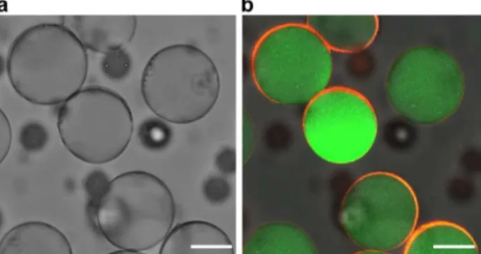
Figure 2. (a) Bright-field microscopy image of PU microshell particles. (b) Fluorescence microscopy image of PU microshell particles with overlaid green and red colors. The scale bars are 20 µm.
highly monodisperse, and their coefficient of variation in size was less than 4%, as shown in Fig. 1c. The solvent in the shell layer was removed by evaporation at room temperature. During evaporation, the diameter of the core remained constant and only the shell thickness decreased. After the removal of all the solvents, the inner and outer interfaces came into contact with each other. This eventually led to generation of a PU precursor interfacial layer with a thickness in the nanometer length scale that is not resoluble by using conventional bright-field images (Fig. 1d and e); this implies that the assembled PG-b-PCL at each interface successfully prevented the destruction of the double emulsion structure, even though the interfacial tension was affected by the evaporation of the solvents.32 Thus, a double emulsion with an extremely thin shell with thickness in the submicrometer range was obtained.
The PEGDA in the core and PU precursor in the shell were polymerized by irradiation with UV light (500 W) for 1 min. To confirm the PU membrane-shelled capsule morphology, FITC-dextran was immobilized in the crosslinked PEGDA hydrogel core, and Nile red, which is a hydrophobic fluorescence dye, was located in the shell layer. The successful detection of the dye in the targeted loci elucidated that the particles have a microshell structure (Fig. 2). To confirm that the shell membrane comprised an elastomeric material, the shell deformation behavior was monitored under applied osmotic pressure. When the core was filled with water, collapse of the spherical shell morphology was usually observed (Fig. 3a). In contrast, when the core comprised a hydrogel phase, buckling typically occurred as the core volume decreased (Fig. 3b); this buckling behavior is irreversible. Distinctive shell deformation was further confirmed via electron microscopic analysis, as shown in Fig. 4a and b. The thickness of the PU shell was in the submicrometer range and depended on the concentration of the PU precursor in the double emulsion shell. These results imply that the periphery of the particles was covered with a flexible but tough PU membrane.
RSC
Advances
Accepted
Journal Name
COMMUNICATION
This journal is © The Royal Society of Chemistry 20xx J. Name., 2013, 00, 1-3 | 3
Please do not adjust margins
Please do not adjust margins
Figure 3. Time series of bright-field microscopy images of PU microshell particles in the presence of osmolality (2 M NaCl). (a) Core is filled with an aqueous phase. (b) Core is filled with a PEGDA hydrogel phase. The scale bars are 50 µm.
We further investigated how the composition affects the formation of the microshell particles. First, the effect of solvents in the double emulsion shell was examined by carrying out direct polymerization without removing solvents from the shell layer. Upon UV irradiation, the core escaped the double emulsion drop, which led to the formation of conventional polymersomes (Fig. S4).22, 33 This behavior occurred irrespective of the phase type of the core, i.e., aqueous or hydrogel phase. Regarding this result, we assume that the generation of hydrophobic PU chains readily makes the spreading coefficient negative, thus facilitating the dewetting phenomenon.34 We also investigated how the hardness of the PU membrane influenced the surface topology of the particles. When the hydrogel-filled shell particles were made with PU, which has a high modulus, they showed a lowered degree of buckling as well as an unevenly buckled surface (Fig. S5a). When the shell collapse was induced in the absence of the hydrogel phase in the core, the high-modulus PU shell membrane folded over to form angled edges (Fig. S5b). These results indicate that the improved shell tolerance could be achieved by incorporating a high-modulus PU to the shell layer.
Figure 4. Scanning electron microscopy images of PU
microshell particles with cores filled with (a) an aqueous phase and (b) a hydrogel phase. Scale bars are 10 µm. (c) Scanning electron microscopy image of a chopped particle. The scale bar is 2.5 µm.
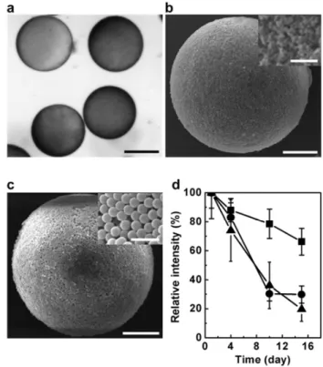
Figure 5. (a) Bright-field microscopy image of W/O/W double emulsion drop containing silica particles in the shell layer. The scale bar is 100 µm. Scanning electron microscopy images of colloidosomes with silica/PU hybrid shells: 100 nm silica particles (b) and 1µm silica particles (c). The scale bars are 20
µm. The scale bars in the inset images of b and c are 1 µm and 3 µm, respectively. (d) Release profile of fluorescein sodium salt from the microshell particles: PU shell only (), 100 nm silica particles (), and 1 µm silica particles (). The experiment was carried out at 25°C.
Having established how to fabricate microcapsules, our next attention has moved to further tailoring the shell structure. In this study, we incorporated solid particles in the PU shell, which led to production of hybrid colloidosomes. For this, first, silica particles were treated with trimethoxy(octadecyl)silane, thus making them hydrophobic. Thanks to the hydrophobic surface, they could be stably dispersed in the middle fluid (silica/PU=8.5/1.5, w/w). The silica/PU hybrid shell was observed using bright field and scanning electron microscopes. Homogeneous immobilization of silica particles could be confirmed by observation of the dark phase throughout the PU shell (Fig. 5a). For the 100 nm silica particles, generation of interstice could be observed, indicating that the silica particles were just immobilized with PU (Fig. 5b). As expected, using the 1 µm silica particles causes them to form bigger voids in the shell (Fig. 5c). Typically, the shell structure of the colloidosomes has been varied by tuning the size of the solid particles, the shell thickness, and the degree of fusion between the particles.35-38 Moreover, the permeation study, in which the shell permeability was evaluated by monitoring the fluorescence intensity of the hydrogel core phase that contained a water-soluble fluorescent molecular probe, fluorescein sodium salt (FSS, 376.27 g⋅mol–1), allowed us to figure out that controlled release could be achieved by hybridization
Page 4 of 5
RSC Advances
RSC
Advances
Accepted
Manuscript
COMMUNICATION
Journal Name
of silica particles with PU shell phase (Fig. 5d). These results highlight that, alternatively, the shell structure can be also tailored through the hybridization of solid particles with the matrix polymer that acts as a binder.
Conclusions
In summary, we fabricated a new type of uniform PU elastomer microcapsules, in which monodisperse W/O/W double emulsions, which were generated using a capillary microfluidic device, were used as templates. The formation of a flexible but tough elastomer shell membrane was confirmed by analysing the particle morphology and surface topology. In our further study, we hybridized silica particles with PU shells to demonstrate that our fabrication method could be used to engineer colloidosomes with a controlled interstice structure. The microcapsule system developed in this study is expected to be applicable to a variety of encapsulation applications such as packaging and storage under harsh environments.
Acknowledgements
This work was supported by Samsung Research Funding Centre of Samsung Electronics under Project Number SRFC-MA1301-07.
Notes and references
1. R. Langer, Nature, 1998, 392, 5.
2. T. M. Allen and P. R. Cullis, Science, 2004, 303, 1818. 3. C. Alvarez-Lorenzo and A. Concheiro, Chem. Commun., 2014,
50, 7743.
4. K. Y. Lee and S. H. Yuk, Prog. Polym. Sci., 2007, 32, 669. 5. V. Noireaux and A. Libchaber, Proc. Natl. Acad. Sci. U.S.A.,
2004, 101, 17669.
6. S. F. van Dongen, W. P. Verdurmen, R. J. Peters, R. J. Nolte, R. Brock and J. van Hest, Angew. Chem. Int. Ed., 2010, 49, 7213.
7. A. Kishimura, A. Koide, K. Osada, Y. Yamasaki and K. Kataoka, Angew. Chem. Int. Ed., 2007, 46, 6085.
8. D. P. Wang and H. C. Zeng, Chem. Mater., 2011, 23, 4886. 9. Y. Q. Lan, H. L. Jiang, S. L. Li and Q. Xu, Adv. Mater., 2011,
23, 5015.
10. D. Lingwood and K. Simons, science, 2010, 327, 46. 11. M. R. Rasch, E. Rossinyol, J. L. Hueso, B. W. Goodfellow, J.
Arbiol and B. A. Korgel, Nano Lett., 2010, 10, 3733. 12. J. S. Hong, S. M. Stavis, S. H. DePaoli Lacerda, L. E.
Locascio, S. R. Raghavan and M. Gaitan, Langmuir, 2010, 26, 11581.
13. D. R. Arifin and A. F. Palmer, Biomacromolecules, 2005, 6, 2172.
14. M. Antonietti and S. Förster, Adv. Mater., 2003, 15, 1323. 15. L. Zhang and A. Eisenberg, Science, 1995, 268, 1728. 16. L. Luo and A. Eisenberg, J. Am. Chem. Soc., 2001, 123, 1012. 17. A. Dinsmore, M. F. Hsu, M. Nikolaides, M. Marquez, A.
Bausch and D. Weitz, Science, 2002, 298, 1006.
18. J.-W. Kim, A. Fernández-Nieves, N. Dan, A. S. Utada, M. Marquez and D. A. Weitz, Nano Lett., 2007, 7, 2876. 19. J. J. Moon, H. Suh, A. Bershteyn, M. T. Stephan, H. Liu, B.
Huang, M. Sohail, S. Luo, S. H. Um and H. Khant, Nat. Mater., 2011, 10, 243.
20. B. Chaize and D. Fournier, Biosens. Bioelectron., 2004, 20, 628.
21. H. Matsuo, J. Chevallier, N. Mayran, I. Le Blanc, C. Ferguson, J. Fauré, N. S. Blanc, S. Matile, J. Dubochet and R. Sadoul,
Science, 2004, 303, 531.
22. Z. Wang, M. van Oers, F. P. Rutjes and J. van Hest, Angew. Chem. Int. Ed., 2012, 51, 10746.
23. H. N. Yow and A. F. Routh, Langmuir, 2008, 25, 159. 24. R. Rodríguez-García, M. Mell, I. López-Montero, J. Netzel, T.
Hellweg and F. Monroy, Soft Matter, 2011, 7, 1532.
25. F. Ahmed and D. E. Discher, J. Control. Release, 2004, 96, 37. 26. J. J. Lin, P. P. Ghoroghchian, Y. Zhang and D. A. Hammer,
Langmuir, 2006, 22, 3975.
27. G.-Y. Liu, X.-S. Liu, S.-S. Wang, C.-J. Chen and J. Ji,
Langmuir, 2011, 28, 557.
28. E. Amstad, S. H. Kim and D. A. Weitz, Angew. Chem., 2012, 124, 12667.
29. M. A. C. Stuart, W. T. Huck, J. Genzer, M. Müller, C. Ober, M. Stamm, G. B. Sukhorukov, I. Szleifer, V. V. Tsukruk and M. Urban, Nat. Mater., 2010, 9, 101.
30. V. D. Gordon, X. Chen, J. W. Hutchinson, A. R. Bausch, M. Marquez and D. A. Weitz, J. Am. Chem. Soc., 2004, 126, 14117.
31. W. Hellmich, J. Regtmeier, T. T. Duong, R. Ros, D. Anselmetti and A. Ros, Langmuir, 2005, 21, 7551. 32. I. D. Rosca, F. Watari and M. Uo, J. Control. Release, 2004,
99, 271.
33. B. M. Discher, Y.-Y. Won, D. S. Ege, J. C. Lee, F. S. Bates, D. E. Discher and D. A. Hammer, Science, 1999, 284, 1143. 34. R. C. Hayward, A. S. Utada, N. Dan and D. A. Weitz,
Langmuir, 2006, 22, 4457.
35. P. F. Noble, O. J. Cayre, R. G. Alargova, O. D. Velev and V. N. Paunov, J. Am. Chem. Soc., 2004, 126, 8092.
36. H. Duan, D. Wang, N. S. Sobal, M. Giersig, D. G. Kurth and H. Möhwald, Nano Lett., 2005, 5, 949.
37. H. Liu, C. Wang, Q. Gao, X. Liu and Z. Tong, Int. J. Pharm., 2008, 351, 104.
38. I. Akartuna, E. Tervoort, A. R. Studart and L. J. Gauckler,
Langmuir, 2009, 25, 12419.